Page 2625 of 4323
A23328
A23329
A23330
(a)(a)
(b)(c)
(c) (c)
B17510
A23331
EM±38
± ENGINE MECHANICALCYLINDER HEAD
2617 Author�: Date�:
2005 SEQUOIA (RM1146U)
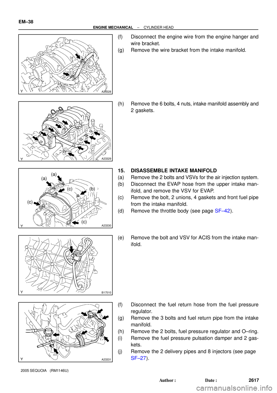
(f) Disconnect the engine wire from the engine hanger and
wire bracket.
(g) Remove the wire bracket from the intake manifold.
(h) Remove the 6 bolts, 4 nuts, intake manifold assembly and
2 gaskets.
15. DISASSEMBLE INTAKE MANIFOLD
(a) Remove the 2 bolts and VSVs for the air injection system.
(b) Disconnect the EVAP hose from the upper intake man-
ifold, and remove the VSV for EVAP.
(c) Remove the bolt, 2 unions, 4 gaskets and front fuel pipe
from the intake manifold.
(d) Remove the throttle body (see page SF±42).
(e) Remove the bolt and VSV for ACIS from the intake man-
ifold.
(f) Disconnect the fuel return hose from the fuel pressure
regulator.
(g) Remove the 3 bolts and fuel return pipe from the intake
manifold.
(h) Remove the 2 bolts, fuel pressure regulator and O±ring.
(i) Remove the fuel pressure pulsation damper and 2 gas-
kets.
(j) Remove the 2 delivery pipes and 8 injectors (see page
SF±27).
Page 2626 of 4323
A23332
Front Water Bypass Joint
A23333
Rear Water Bypass Joint
A05564
± ENGINE MECHANICALCYLINDER HEAD
EM±39
2618 Author�: Date�:
2005 SEQUOIA (RM1146U)
16. REMOVE WATER INLET AND INLET HOUSING AS-
SEMBLY (See page CO±6)
17. REMOVE AIR PUMP ASSEMBLY (See page EC±22)
18. REMOVE NO.2 AIR SWITCHING VALVES
(See page EC±22)
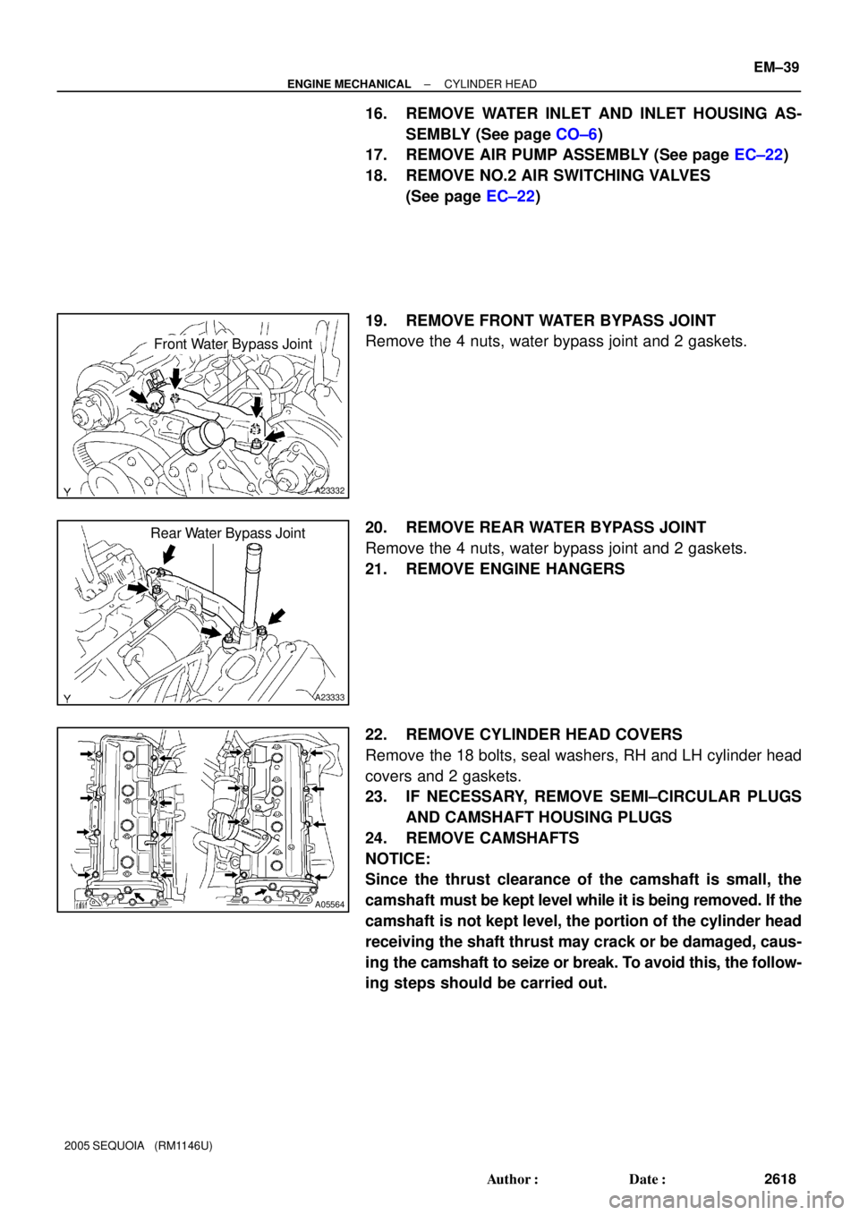
19. REMOVE FRONT WATER BYPASS JOINT
Remove the 4 nuts, water bypass joint and 2 gaskets.
20. REMOVE REAR WATER BYPASS JOINT
Remove the 4 nuts, water bypass joint and 2 gaskets.
21. REMOVE ENGINE HANGERS
22. REMOVE CYLINDER HEAD COVERS
Remove the 18 bolts, seal washers, RH and LH cylinder head
covers and 2 gaskets.
23. IF NECESSARY, REMOVE SEMI±CIRCULAR PLUGS
AND CAMSHAFT HOUSING PLUGS
24. REMOVE CAMSHAFTS
NOTICE:
Since the thrust clearance of the camshaft is small, the
camshaft must be kept level while it is being removed. If the
camshaft is not kept level, the portion of the cylinder head
receiving the shaft thrust may crack or be damaged, caus-
ing the camshaft to seize or break. To avoid this, the follow-
ing steps should be carried out.
Page 2630 of 4323
A233435 mm Hexagon Wrench SST
B02642B02644A04229
RH Bank
LH Bank1
23 4
5 6
7
89
10
3
1 5
7 10
9 8
6 2
4
B02643
B02645A04230
Portion A
Portion A RH Bank
LH Bank
± ENGINE MECHANICALCYLINDER HEAD
EM±43
2622 Author�: Date�:
2005 SEQUOIA (RM1146U)
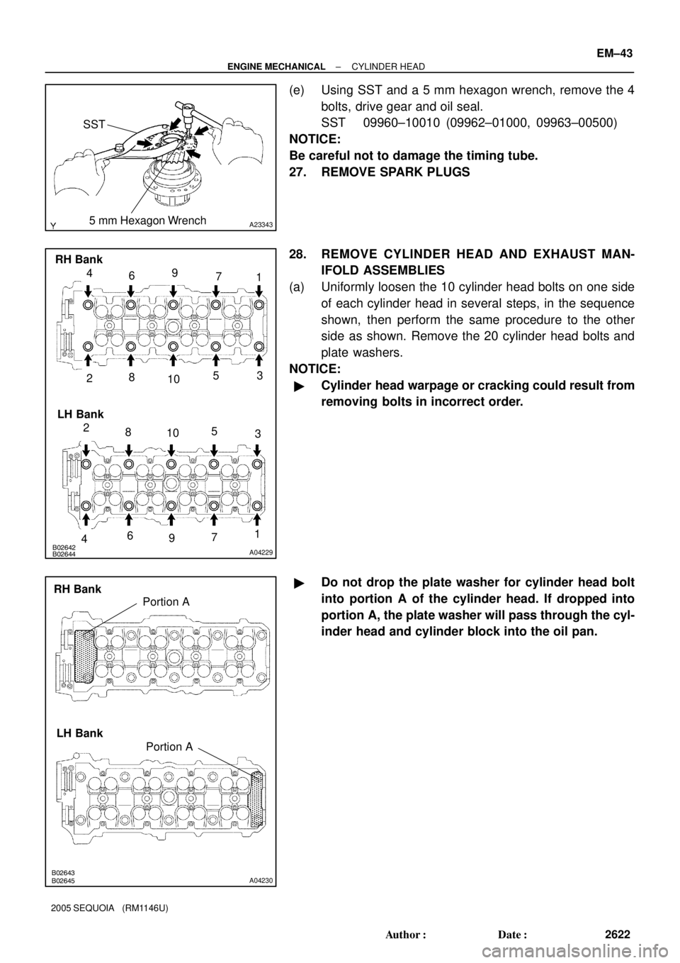
(e) Using SST and a 5 mm hexagon wrench, remove the 4
bolts, drive gear and oil seal.
SST 09960±10010 (09962±01000, 09963±00500)
NOTICE:
Be careful not to damage the timing tube.
27. REMOVE SPARK PLUGS
28. REMOVE CYLINDER HEAD AND EXHAUST MAN-
IFOLD ASSEMBLIES
(a) Uniformly loosen the 10 cylinder head bolts on one side
of each cylinder head in several steps, in the sequence
shown, then perform the same procedure to the other
side as shown. Remove the 20 cylinder head bolts and
plate washers.
NOTICE:
�Cylinder head warpage or cracking could result from
removing bolts in incorrect order.
�Do not drop the plate washer for cylinder head bolt
into portion A of the cylinder head. If dropped into
portion A, the plate washer will pass through the cyl-
inder head and cylinder block into the oil pan.
Page 2634 of 4323
EM6325
A05592
EM6327
A21018
50 mm
(1.96 in.) Measuring
Point
± ENGINE MECHANICALCYLINDER HEAD
EM±47
2626 Author�: Date�:
2005 SEQUOIA (RM1146U)
5. CLEAN CYLINDER HEAD
Using a soft brush and solvent, thoroughly clean the cylinder
head.
6. INSPECT FOR FLATNESS
Using a precision straight edge and feeler gauge, measure the
surfaces contacting the cylinder block and the manifolds for
warpage.
Maximum warpage: 0.10 mm (0.0039 in.)
If warpage is greater than maximum, replace the cylinder head.
7. INSPECT FOR CRACKS
Using a dye penetrate, check the combustion chamber, intake
ports, exhaust ports and cylinder block surface for cracks.
If cracked, replace the cylinder head.
8. INSPECT CYLINDER HEAD BOLT
Using vernier calipers, measure the thread outside diameter of
the cylinder head bolt.
Standard outside diameter:
9.810 to 9.960 mm (0.3862 to 0.3921 in.)
Minimum outside diameter: 9.70 mm (0.3819 in.)
If the diameter is less than minimum, replace the bolt.
Page 2635 of 4323
EM0580
A04087A04091A04236
Z00052
Z00054
44.5° EM±48
± ENGINE MECHANICALCYLINDER HEAD
2627 Author�: Date�:
2005 SEQUOIA (RM1146U)
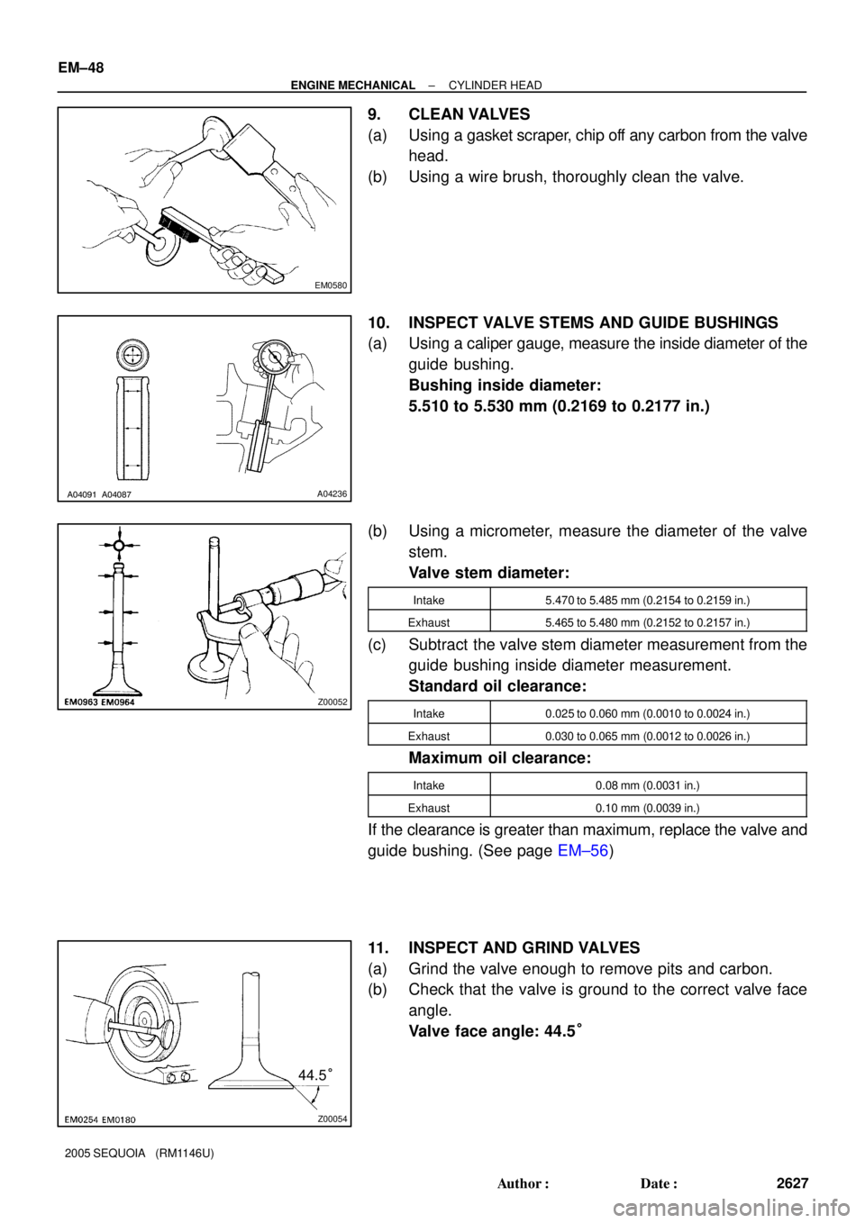
9. CLEAN VALVES
(a) Using a gasket scraper, chip off any carbon from the valve
head.
(b) Using a wire brush, thoroughly clean the valve.
10. INSPECT VALVE STEMS AND GUIDE BUSHINGS
(a) Using a caliper gauge, measure the inside diameter of the
guide bushing.
Bushing inside diameter:
5.510 to 5.530 mm (0.2169 to 0.2177 in.)
(b) Using a micrometer, measure the diameter of the valve
stem.
Valve stem diameter:
Intake5.470 to 5.485 mm (0.2154 to 0.2159 in.)
Exhaust5.465 to 5.480 mm (0.2152 to 0.2157 in.)
(c) Subtract the valve stem diameter measurement from the
guide bushing inside diameter measurement.
Standard oil clearance:
Intake0.025 to 0.060 mm (0.0010 to 0.0024 in.)
Exhaust0.030 to 0.065 mm (0.0012 to 0.0026 in.)
Maximum oil clearance:
Intake0.08 mm (0.0031 in.)
Exhaust0.10 mm (0.0039 in.)
If the clearance is greater than maximum, replace the valve and
guide bushing. (See page EM±56)
11. INSPECT AND GRIND VALVES
(a) Grind the valve enough to remove pits and carbon.
(b) Check that the valve is ground to the correct valve face
angle.
Valve face angle: 44.5°
Page 2639 of 4323
A04022
A23346
A23347
Turn
EM3322
A04083
Plastigage
EM±52
± ENGINE MECHANICALCYLINDER HEAD
2631 Author�: Date�:
2005 SEQUOIA (RM1146U)
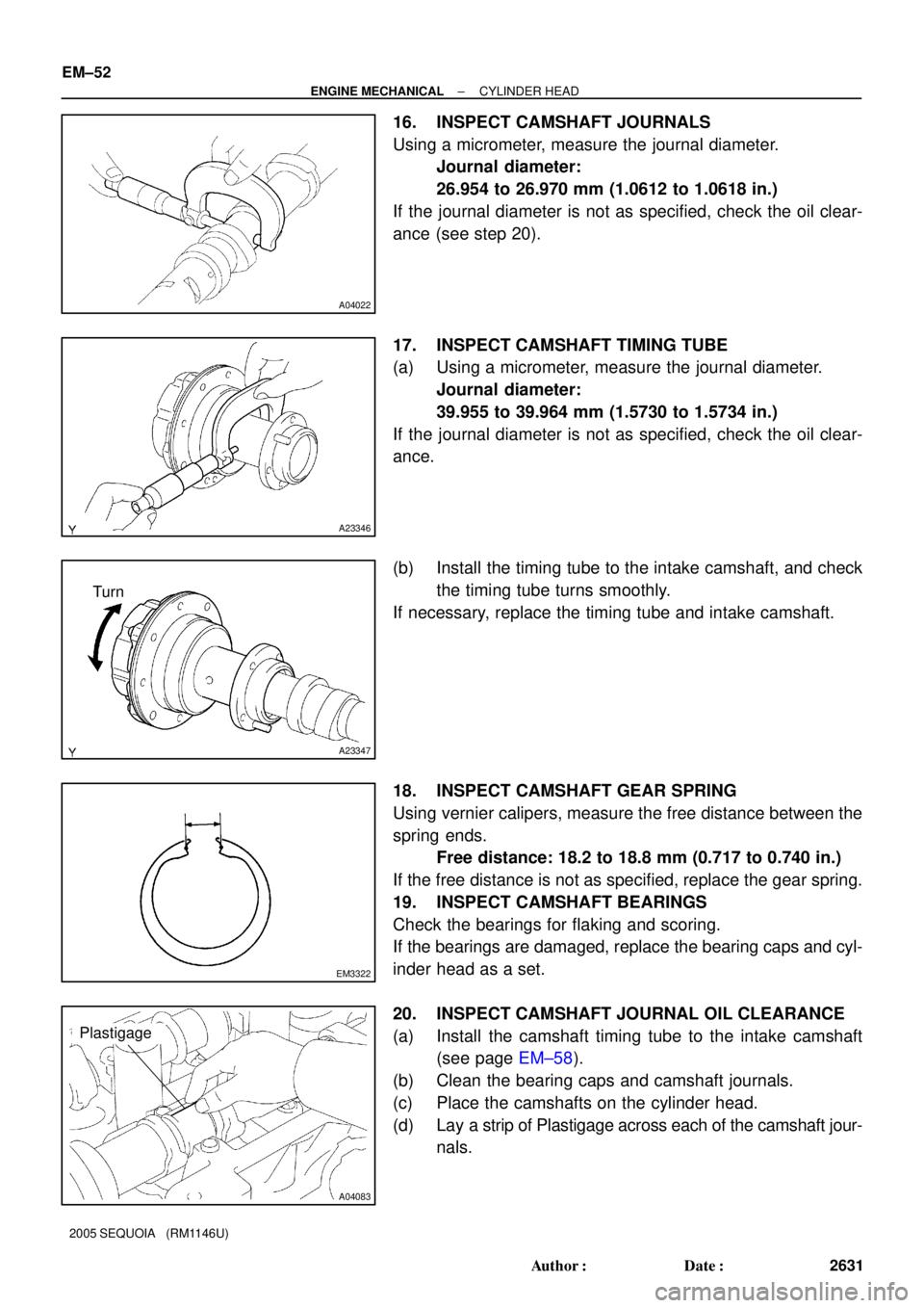
16. INSPECT CAMSHAFT JOURNALS
Using a micrometer, measure the journal diameter.
Journal diameter:
26.954 to 26.970 mm (1.0612 to 1.0618 in.)
If the journal diameter is not as specified, check the oil clear-
ance (see step 20).
17. INSPECT CAMSHAFT TIMING TUBE
(a) Using a micrometer, measure the journal diameter.
Journal diameter:
39.955 to 39.964 mm (1.5730 to 1.5734 in.)
If the journal diameter is not as specified, check the oil clear-
ance.
(b) Install the timing tube to the intake camshaft, and check
the timing tube turns smoothly.
If necessary, replace the timing tube and intake camshaft.
18. INSPECT CAMSHAFT GEAR SPRING
Using vernier calipers, measure the free distance between the
spring ends.
Free distance: 18.2 to 18.8 mm (0.717 to 0.740 in.)
If the free distance is not as specified, replace the gear spring.
19. INSPECT CAMSHAFT BEARINGS
Check the bearings for flaking and scoring.
If the bearings are damaged, replace the bearing caps and cyl-
inder head as a set.
20. INSPECT CAMSHAFT JOURNAL OIL CLEARANCE
(a) Install the camshaft timing tube to the intake camshaft
(see page EM±58).
(b) Clean the bearing caps and camshaft journals.
(c) Place the camshafts on the cylinder head.
(d) Lay a strip of Plastigage across each of the camshaft jour-
nals.
Page 2640 of 4323
A04099A A
A04084
A23348
± ENGINE MECHANICALCYLINDER HEAD
EM±53
2632 Author�: Date�:
2005 SEQUOIA (RM1146U)
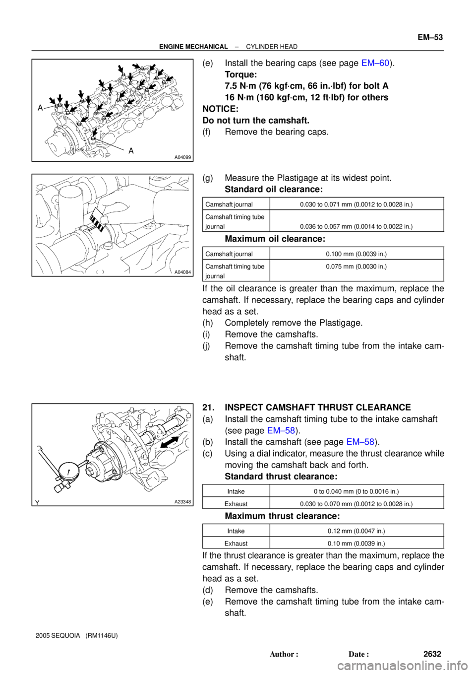
(e) Install the bearing caps (see page EM±60).
Torque:
7.5 N´m (76 kgf´cm, 66 in.´lbf) for bolt A
16 N´m (160 kgf´cm, 12 ft´lbf) for others
NOTICE:
Do not turn the camshaft.
(f) Remove the bearing caps.
(g) Measure the Plastigage at its widest point.
Standard oil clearance:
Camshaft journal0.030 to 0.071 mm (0.0012 to 0.0028 in.)
Camshaft timing tube
journal
0.036 to 0.057 mm (0.0014 to 0.0022 in.)
Maximum oil clearance:
Camshaft journal0.100 mm (0.0039 in.)
Camshaft timing tube
journal0.075 mm (0.0030 in.)
If the oil clearance is greater than the maximum, replace the
camshaft. If necessary, replace the bearing caps and cylinder
head as a set.
(h) Completely remove the Plastigage.
(i) Remove the camshafts.
(j) Remove the camshaft timing tube from the intake cam-
shaft.
21. INSPECT CAMSHAFT THRUST CLEARANCE
(a) Install the camshaft timing tube to the intake camshaft
(see page EM±58).
(b) Install the camshaft (see page EM±58).
(c) Using a dial indicator, measure the thrust clearance while
moving the camshaft back and forth.
Standard thrust clearance:
Intake0 to 0.040 mm (0 to 0.0016 in.)
Exhaust0.030 to 0.070 mm (0.0012 to 0.0028 in.)
Maximum thrust clearance:
Intake0.12 mm (0.0047 in.)
Exhaust0.10 mm (0.0039 in.)
If the thrust clearance is greater than the maximum, replace the
camshaft. If necessary, replace the bearing caps and cylinder
head as a set.
(d) Remove the camshafts.
(e) Remove the camshaft timing tube from the intake cam-
shaft.
Page 2641 of 4323
A04082
A03209
A03201
12.3 to 12.7 mm
EM±54
± ENGINE MECHANICALCYLINDER HEAD
2633 Author�: Date�:
2005 SEQUOIA (RM1146U)
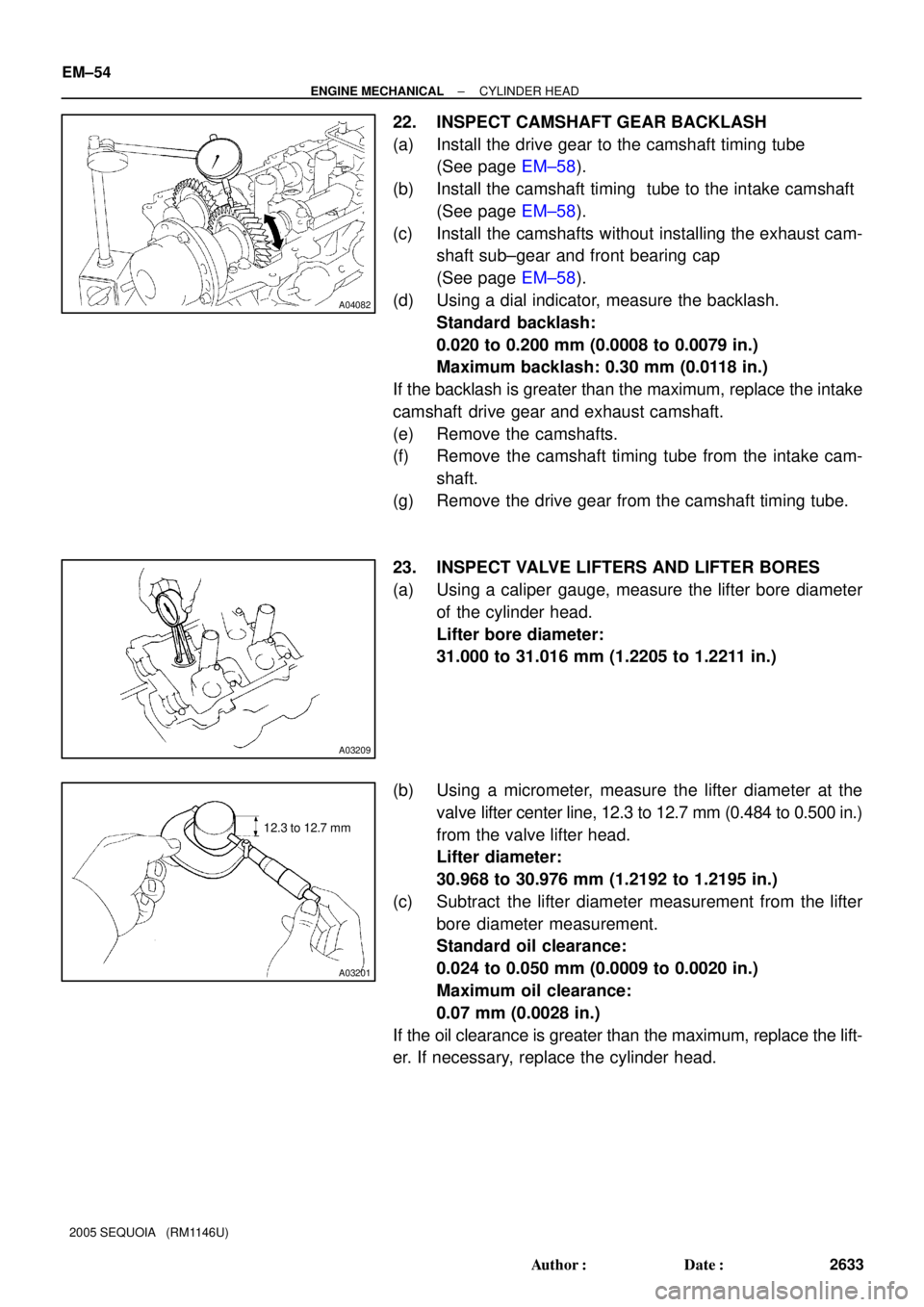
22. INSPECT CAMSHAFT GEAR BACKLASH
(a) Install the drive gear to the camshaft timing tube
(See page EM±58).
(b) Install the camshaft timing tube to the intake camshaft
(See page EM±58).
(c) Install the camshafts without installing the exhaust cam-
shaft sub±gear and front bearing cap
(See page EM±58).
(d) Using a dial indicator, measure the backlash.
Standard backlash:
0.020 to 0.200 mm (0.0008 to 0.0079 in.)
Maximum backlash: 0.30 mm (0.0118 in.)
If the backlash is greater than the maximum, replace the intake
camshaft drive gear and exhaust camshaft.
(e) Remove the camshafts.
(f) Remove the camshaft timing tube from the intake cam-
shaft.
(g) Remove the drive gear from the camshaft timing tube.
23. INSPECT VALVE LIFTERS AND LIFTER BORES
(a) Using a caliper gauge, measure the lifter bore diameter
of the cylinder head.
Lifter bore diameter:
31.000 to 31.016 mm (1.2205 to 1.2211 in.)
(b) Using a micrometer, measure the lifter diameter at the
valve lifter center line, 12.3 to 12.7 mm (0.484 to 0.500 in.)
from the valve lifter head.
Lifter diameter:
30.968 to 30.976 mm (1.2192 to 1.2195 in.)
(c) Subtract the lifter diameter measurement from the lifter
bore diameter measurement.
Standard oil clearance:
0.024 to 0.050 mm (0.0009 to 0.0020 in.)
Maximum oil clearance:
0.07 mm (0.0028 in.)
If the oil clearance is greater than the maximum, replace the lift-
er. If necessary, replace the cylinder head.