Page 2702 of 4323
A05121
A05854A05122A05169
± ENGINE MECHANICALCYLINDER BLOCK
EM±115
2694 Author�: Date�:
2005 SEQUOIA (RM1146U)
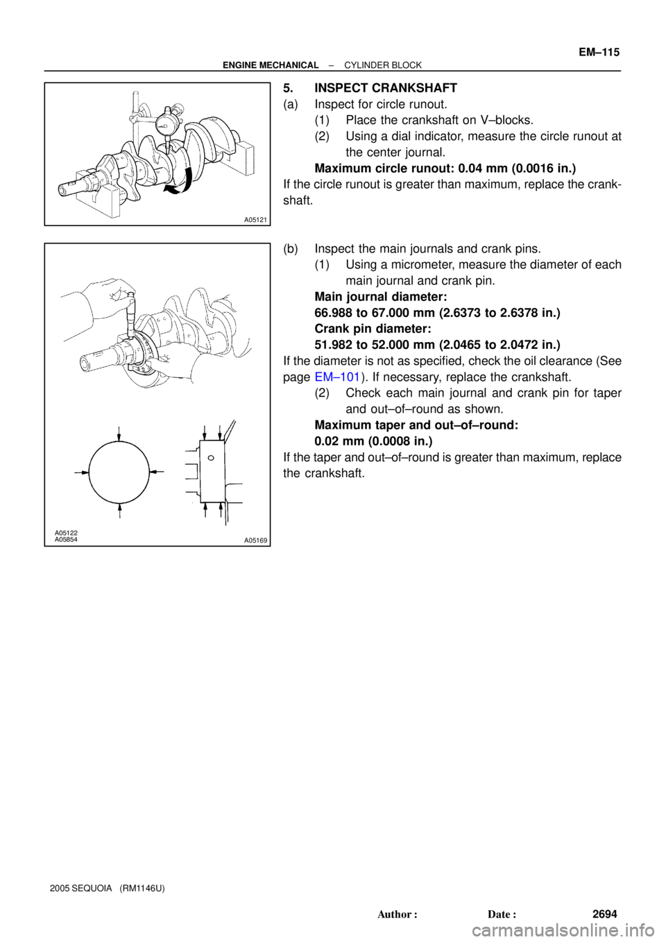
5. INSPECT CRANKSHAFT
(a) Inspect for circle runout.
(1) Place the crankshaft on V±blocks.
(2) Using a dial indicator, measure the circle runout at
the center journal.
Maximum circle runout: 0.04 mm (0.0016 in.)
If the circle runout is greater than maximum, replace the crank-
shaft.
(b) Inspect the main journals and crank pins.
(1) Using a micrometer, measure the diameter of each
main journal and crank pin.
Main journal diameter:
66.988 to 67.000 mm (2.6373 to 2.6378 in.)
Crank pin diameter:
51.982 to 52.000 mm (2.0465 to 2.0472 in.)
If the diameter is not as specified, check the oil clearance (See
page EM±101). If necessary, replace the crankshaft.
(2) Check each main journal and crank pin for taper
and out±of±round as shown.
Maximum taper and out±of±round:
0.02 mm (0.0008 in.)
If the taper and out±of±round is greater than maximum, replace
the crankshaft.
Page 2704 of 4323

(d) Using a pin hole grinder, hone the bushing to obtain the")
P20667
P20668
A04868
A04867
SST
A04858Cut Position
± ENGINE MECHANICALCYLINDER BLOCK
EM±117
2696 Author�: Date�:
2005 SEQUOIA (RM1146U)
(d) Using a pin hole grinder, hone the bushing to obtain the
standard specified clearance (See page EM±101) be-
tween the bushing and piston pin.
(e) Check the piston pin fit at normal room temperature. Coat
the piston pin with engine oil, and push it into the connect-
ing rod with your thumb.
3. REPLACE CRANKSHAFT FRONT OIL SEAL (See
page LU±13)
4. REPLACE CRANKSHAFT REAR OIL SEAL
HINT:
There are 2 methods ((a) and (b)) to replace the oil seal.
(a) If the rear oil seal retainer is removed from the cylinder
block:
(1) Using a screwdriver and hammer, tap out the oil
seal.
(2) Using SST and a hammer, tap in a new oil seal until
its surface is flush with the rear oil seal retainer
edge.
SST 09223±56010
(3) Apply MP grease to the oil seal lip.
(b) If the rear oil seal retainer is installed to the cylinder block:
(1) Using a knife, cut off the oil seal lip.
(2) Using a screwdriver, pry out the oil seal.
NOTICE:
Be careful not to damage the crankshaft. Tape the screw-
driver tip.
Page 2709 of 4323

Front
LH
Piston
RH
PistonFront
Front Mark
(2 Cavities)
EM±122
± ENGINE MECHANICALCYLINDER BLOCK
2701 Aut")
A05095
1
248
6
3
5
9
7
10
A05094
Front
Painted
Mark90° 90°
A23371
Front Mark
(1 Cavity)
Front
LH
Piston
RH
PistonFront
Front Mark
(2 Cavities)
EM±122
± ENGINE MECHANICALCYLINDER BLOCK
2701 Author�: Date�:
2005 SEQUOIA (RM1146U)
(a) Apply a light coat of engine oil to the threads and under
the main bearing cap bolts.
(b) Install and uniformly tighten the 10 main bearing cap bolts
in several steps, in the sequence shown.
Torque: 27 N´m (275 kgf´cm, 20 ft´lbf)
If any of the main bearing cap bolts does not meet the torque
specification, replace the main bearing cap bolt.
(c) Mark the front of the main bearing cap bolt with paint.
(d) Retighten the main bearing cap bolts by 90° in the numer-
ical order shown.
(e) Check that the painted mark is now at a 90° angle to the
front.
(f) Check that the crankshaft turns smoothly.
9. CHECK CRANKSHAFT THRUST CLEARANCE
(See page EM±101)
10. INSTALL PISTON AND CONNECTING ROD AS-
SEMBLIES
Using a piston ring compressor, push correctly the numbered
piston and connecting rod assemblies into each cylinder with
the front mark of the piston facing forward.
NOTICE:
The shape of the piston differs for the LH and RH banks.
The LH piston is marked with 1 cavity and º2º, the RH pis-
ton with 2 cavities and º2º.
Page 2710 of 4323

RH Bank LH Bank
Front
Outside Mark
(Protrusion)
A05101
A05099
Painted
Mark Front90°
90°
± ENGINE MECHANICALCYLINDER BLOCK
EM±123
2702 Auth")
A05106
A05107A05108A05174
Front
Outside Mark
(Protrusion)
RH Bank LH Bank
Front
Outside Mark
(Protrusion)
A05101
A05099
Painted
Mark Front90°
90°
± ENGINE MECHANICALCYLINDER BLOCK
EM±123
2702 Author�: Date�:
2005 SEQUOIA (RM1146U)
11. PLACE CONNECTING ROD CAP ON CONNECTING
ROD
(a) Match the numbered connecting rod cap with the con-
necting rod.
(b) Align the pin groove of the connecting rod cap with the
pins of the connecting rod, and install the connecting rod
cap.
(c) Check that the outside mark of the connecting rod cap is
facing in correct direction.
12. INSTALL CONNECTING ROD CAP BOLTS
HINT:
�The connecting rod cap bolts are tightened in 2 progres-
sive steps (steps (b) and (d)).
�If any one of the connecting rod cap bolts is broken or de-
formed, replace it.
(a) Apply a light coat of engine oil on the threads and under
the heads of the connecting rod cap bolts.
(b) Install and alternately tighten the 2 connecting rod cap
bolts in several passes.
Torque: 24.5 N´m (250 kgf´cm, 18 ft´lbf)
If any one of the connecting rod cap bolts does not meet the
torque specification, replace the connecting rod cap bolts.
(c) Mark the front of the connecting cap bolt with paint.
(d) Retighten the cap bolts by 90° as shown.
(e) Check that the painted mark is now at a 90° angle to the
front.
(f) Check that the crankshaft turns smoothly.
13. CHECK CONNECTING ROD THRUST CLEARANCE
(See page EM±101)
Page 2712 of 4323

(b) Install the 2 drain unions.
Torque: 49 N")
A04856
FrontPort
A08472
LH Side
A05132
Push
Wire
Clamp
New
O±Ring
± ENGINE MECHANICALCYLINDER BLOCK
EM±125
2704 Author�: Date�:
2005 SEQUOIA (RM1146U)
(b) Install the 2 drain unions.
Torque: 49 N´m (500 kgf´cm, 36 ft´lbf)
HINT:
After applying the specified torque, rotate the drain union clock-
wise until its drain port is facing forward.
16. INSTALL OIL PUMP (See page LU±15)
17. INSTALL OIL STRAINER (See page LU±15)
18. INSTALL NO.1 OIL PAN (See page LU±15)
19. INSTALL OIL PAN BAFFLE PLATE
(See page LU±15)
20. INSTALL NO.2 OIL PAN (See page LU±15)
21. INSTALL WATER PUMP (See page CO±8)
22. INSTALL ENGINE MOUNTING BRACKETS
Install the mounting bracket with the 4 bolts. Install the 2 mount-
ing brackets.
Torque: 36 N´m (370 kgf´cm, 27 ft´lbf)
23. INSTALL ENGINE WIRE TO LH SIDE OF CYLINDER
BLOCK
(a) Install the brackets on the engine wire with the 2 bolts.
(b) Install the engine wire cover with the 2 bolts.
24. INSTALL OIL COOLER PIPE BRACKET FOR A/T
Install the bracket with the bolt.
25. INSTALL VVT SENSORS (See page SF±77)
26. INSTALL KNOCK SENSORS (See page SF±66)
27. INSTALL STARTER (See page ST±16)
28. INSTALL WATER BYPASS PIPE
(a) Install a new O±ring to the water bypass pipe.
(b) Apply soapy water to the O±ring.
(c) Push in the water bypass pipe end into the pipe hole of
the water pump.
(d) Install the water bypass pipe with the bolt.
Torque: 18 N´m (185 kgf´cm, 13 ft´lbf)
(e) Install the wire clamp to the bracket of the water bypass
pipe.
29. INSTALL CYLINDER HEADS (See page EM±60)
30. INSTALL TIMING BELT AND PULLEYS
(See page EM±23)
31. DISCONNECT ENGINE FROM ENGINE STAND
Page 2729 of 4323
 CONTROL SYSTEM
EC±13
2721 Author�: Date�:
2")
B17663
Port APurge Port
Vent PortAir Inlet Port
Pressure Gauge Port B
B17603
A
B C
Air
B17604
7Closed
Valve6
± EMISSION CONTROLEVAPORATIVE EMISSION (EVAP) CONTROL SYSTEM
EC±13
2721 Author�: Date�:
2005 SEQUOIA (RM1146U)
(c) Check for air leakage.
(1) Remove the air hose between ports A and B.
(2) Connect the pressure gauge to the vent port of the
charcoal canister.
(3) While holding port B, with the purge port and the air
inlet port closed and port A open, apply pressurized
air 19.6 kPa (0.2 kgf/cm
2, 2.81 psi) of pressurized
air into the vent port, then confirm that the pressure
is retained for 1 minute.
If the result is not as specified, replace the charcoal canister as-
sembly.
(d) Check leak detection pump.
(1) Remove the detection pump from the charcoal can-
ister.
(2) Check that air flows from port A to B and then C.
If the result is not as specified, replace the charcoal canister as-
sembly.
(3) Connect the positive (+) lead to terminal 7 and the
negative (±) lead to terminal 6.
(4) Check that the valve is closed.
If the result is not as specified, replace the charcoal canister as-
sembly.
(5) Install the detection pump.
9. INSPECT VSV FOR EVAP (See page SF±63)
10. REINSTALL CHARCOAL CANISTER ASSEMBLY
Page 2738 of 4323

REMOVAL
1. REMOVE THROTTLE BODY COVER
2. REMOVE INTA")
EC0O0±01
B17520
B17521
B17522
B17523
B17524
EC±22
± EMISSION CONTROLSECONDARY AIR INJECTION SYSTEM
2730 Author�: Date�:
2005 SEQUOIA (RM1146U)
REMOVAL
1. REMOVE THROTTLE BODY COVER
2. REMOVE INTAKE MANIFOLD (See page EM±36)
3. REMOVE VSV FOR AIR INJECTION SYSTEM
(a) Remove the 2 bolts and 2 VSVs from the intake manifold.
(b) Remove the 2 vacuum hoses from the 2 VSVs.
4. REMOVE AIR PUMP ASSEMBLY
(a) Disconnect the air hose No.2 from the air switching valve.
(b) Disconnect the air switching valve connector.
(c) Disconnect the pressure sensor connector for the air in-
jection system.
(d) Remove the 4 bolts and air pump assembly.
5. REMOVE NO. 2 AIR SWITCHING VALVE
(a) Remove the 4 nuts and 2 gaskets, and disconnect the 2
No.3 air tubes from the exhaust manifolds.
(b) Remove the 4 bolts, 2 gaskets and the 2 No.3 air tubes
from the 2 No.2 air switching valves.
(c) Remove the 4 bolts, 2 gaskets and the 2 No.2 air switch-
ing valves from the rear water by±pass joint.
(d) Remove the 2 vacuum hoses from the No.2 air switching
valves.
6. REMOVE AIR INJECTION CONTROL DRIVER
(a) Disconnect the 2 connectors from the air injection control
driver.
(b) Remove the 2 bolts and air injection control driver from
the body.
Page 2742 of 4323

INSTALLATION
1. INSTALL AIR INJECTION CONTROL DRIVER")
EC0O4±01
B17524
B17523
B17522
B17521
B17520
EC±26
± EMISSION CONTROLSECONDARY AIR INJECTION SYSTEM
2734 Author�: Date�:
2005 SEQUOIA (RM1146U)
INSTALLATION
1. INSTALL AIR INJECTION CONTROL DRIVER
(a) Install the air injection control driver with the 2 bolts to the
body.
Torque: 18 N´m (184 kgf´cm, 13 ft´lbf)
(b) Connect the 2 connectors to the air injection control driv-
er.
2. INSTALL NO. 2 AIR SWITCHING VALVE
(a) Connect the 2 vacuum hoses to the No.2 air switching
valves.
(b) Install 2 new gaskets and 2 No.2 air switching valves with
the 4 bolts to the rear water by±pass joint.
Torque: 10 N´m (102 kgf´cm, 7 ft´lbf)
(c) Install 2 new gaskets, and connect the 2 No.3 air tubes
with the 4 bolts to the No.2 air switching valve.
Torque: 10 N´m (102 kgf´cm, 7 ft´lbf)
(d) Install the 2 new gaskets, and connect the 2 No.3 air
tubes with the 4 nuts to the exhaust manifold.
Torque: 10 N´m (102 kgf´cm, 7 ft´lbf)
3. INSTALL AIR PUMP ASSEMBLY
(a) Install the air pump assembly with the 4 bolts.
Torque: 16 N´m (163 kgf´cm, 12 ft´lbf)
(b) Connect the pressure sensor connector for the air injec-
tion system.
(c) Connect the air switching valve connector.
(d) Connect the air hose No.2 to the air switching valve.
4. INSTALL VSV FOR AIR INJECTION SYSTEM
(a) Install the 2 VSVs with the 2 bolts to the intake manifold.
Torque: 7.5 N´m (76 kgf´cm, 66 in.´lbf)
(b) Connect the 2 vacuum hoses to the 2 VSVs.
5. INSTALL INTAKE MANIFOLD (See page EM±60)
6. INSTALL THROTTLE BODY COVER