Page 2877 of 4323
IG08U±08
B17487
IG±8
± IGNITIONCAMSHAFT POSITION SENSOR
2869 Author�: Date�:
2005 SEQUOIA (RM1146U)
REMOVAL
1. DRAIN ENGINE COOLANT
2. REMOVE DRIVE BELT (See page CH±7)
3. REMOVE LH NO.3 TIMING BELT COVER
(See page EM±16)
4. REMOVE CAMSHAFT POSITION SENSOR
Remove the bolt, stud bolt and camshaft position sensor.
Page 2878 of 4323
IG08V±06
B17487
± IGNITIONCAMSHAFT POSITION SENSOR
IG±9
2870 Author�: Date�:
2005 SEQUOIA (RM1146U)
INSTALLATION
1. INSTALL CAMSHAFT POSITION SENSOR
Install the camshaft position sensor with the bolt and stud bolt
Torque: 7.5 N´m (80 kgf´cm, 66 in.´lbf)
2. INSTALL LH NO.3 TIMING BELT COVER
(See page EM±23)
3. INSTALL DRIVE BELT (See page CH±16)
4. FILL ENGINE COOLANT (See page CO±2)
5. CHECK ENGINE COOLANT FOR LEAKS
6. CHECK IGNITION TIMING (See page EM±9)
Page 2887 of 4323
ST08Z±07
B04548
B04549
Starter
Connector
Engine Wire Protector
± STARTINGSTARTER
ST±5
2879 Author�: Date�:
2005 SEQUOIA (RM1146U)
REMOVAL
1. REMOVE THROTTLE BODY COVER
2. REMOVE INTAKE AIR CONNECTOR
3. DISCONNECT CABLE FROM NEGATIVE (±) BATTERY
TERMINAL
4. DISCONNECT THROTTLE BODY ASSEMBLY FROM
INTAKE MANIFOLD (See page SF±42)
5. REMOVE INTAKE MANIFOLD ASSEMBLY
(See page EM±36)
6. REMOVE AIR PUMP ASSEMBLY (See page EC±22)
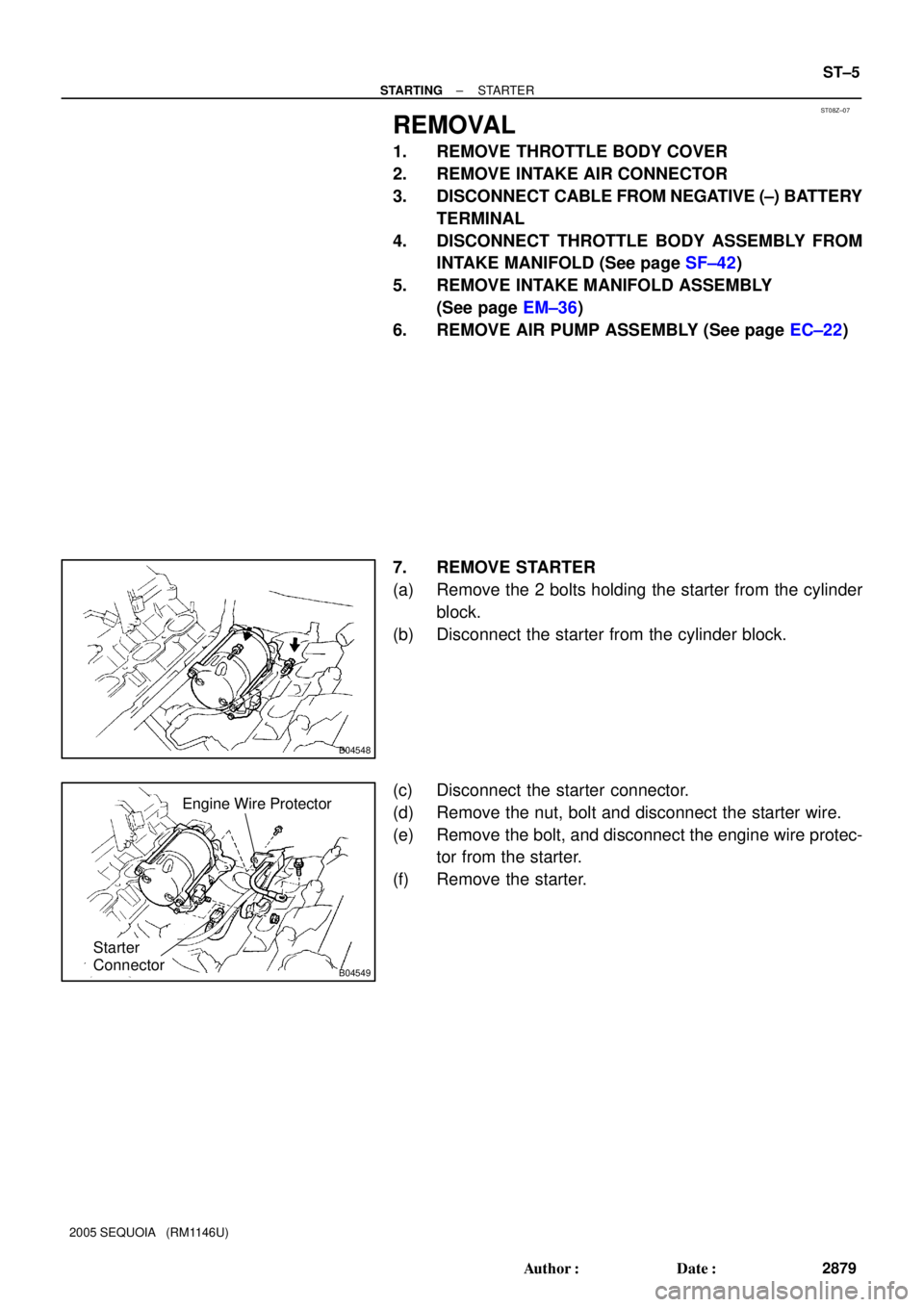
7. REMOVE STARTER
(a) Remove the 2 bolts holding the starter from the cylinder
block.
(b) Disconnect the starter from the cylinder block.
(c) Disconnect the starter connector.
(d) Remove the nut, bolt and disconnect the starter wire.
(e) Remove the bolt, and disconnect the engine wire protec-
tor from the starter.
(f) Remove the starter.
Page 2896 of 4323
ST093±03
ST±14
± STARTINGSTARTER
2888 Author�: Date�:
2005 SEQUOIA (RM1146U)
REASSEMBLY
Reassembly is in the reverse order of disassembly (See page ST±6).
HINT:
At the time of assembly, use high±temperature grease to lubricate the bearing and gears when assembling
the starter.
Page 2898 of 4323
ST095±06
B04549
Starter
Connector
Engine Wire Protector
B04548
ST±16
± STARTINGSTARTER
2890 Author�: Date�:
2005 SEQUOIA (RM1146U)
INSTALLATION
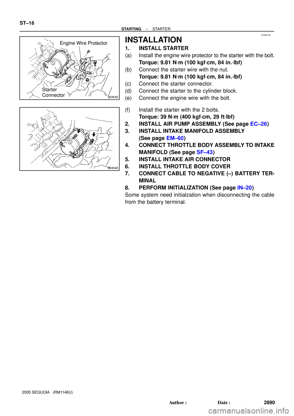
1. INSTALL STARTER
(a) Install the engine wire protector to the starter with the bolt.
Torque: 9.81 N´m (100 kgf´cm, 84 in.´lbf)
(b) Connect the starter wire with the nut.
Torque: 9.81 N´m (100 kgf´cm, 84 in.´lbf)
(c) Connect the starter connector.
(d) Connect the starter to the cylinder block.
(e) Connect the engine wire with the bolt.
(f) Install the starter with the 2 bolts.
Torque: 39 N´m (400 kgf´cm, 29 ft´lbf)
2. INSTALL AIR PUMP ASSEMBLY (See page EC±26)
3. INSTALL INTAKE MANIFOLD ASSEMBLY
(See page EM±60)
4. CONNECT THROTTLE BODY ASSEMBLY TO INTAKE
MANIFOLD (See page SF±43)
5. INSTALL INTAKE AIR CONNECTOR
6. INSTALL THROTTLE BODY COVER
7. CONNECT CABLE TO NEGATIVE (±) BATTERY TER-
MINAL
8. PERFORM INITIALIZATION (See page IN±20)
Some system need initialzation when disconnecting the cable
from the battery terminal.
Page 2907 of 4323
CH0LY±02
B00809
± CHARGINGGENERATOR
CH±7
2899 Author�: Date�:
2005 SEQUOIA (RM1146U)
REMOVAL
1. REMOVE ENGINE UNDER COVER
2. REMOVE THROTTLE BODY COVER
3. DISCONNECT CABLE FROM NEGATIVE (±) BATTERY
TERMINAL
4. DISCONNECT INTAKE AIR CONNECTOR FROM
THROTTLE BODY
5. REMOVE DRIVE BELT
Loosen the belt tension by turning the belt tensioner counter-
clockwise, and remove the drive belt.
HINT:
The pulley bolt for the belt tensioner has a left hand thread.
6. REMOVE PS VANE PUMP FROM ENGINE
(See page SR±28)
7. REMOVE GENERATOR
(a) Disconnect the generator connector.
(b) Remove the terminal cap and nut, and disconnect the
generator wire.
(c) Disconnect the wire clamp from the cord clip on the gener-
ator.
(d) Remove the bolt, the 2 nuts and the generator.
Page 2910 of 4323

INSPECTION
1. INSPECT ROTOR
(a) Check")
CH0M0±02
B12264
Ohmmeter
Continuity
B12265
Ohmmeter
No Continuity
B12266
B16374
Length CH±10
± CHARGINGGENERATOR
2902 Author�: Date�:
2005 SEQUOIA (RM1146U)
INSPECTION
1. INSPECT ROTOR
(a) Check the rotor for open circuit.
Using an ohmmeter, check that there is continuity be-
tween the slip rings.
Standard resistance: 1.5 to 1.9 W at 20°C (68°F)
If there is no continuity, replace the rotor.
(b) Check the rotor for ground.
Using an ohmmeter, check that there is no continuity be-
tween the slip ring and rotor.
If there is continuity, replace the rotor.
(c) Check that the slip rings are not rough or scored.
If rough or scored, replace the rotor.
(d) Using vernier calipers, measure the slip ring diameter.
Standard diameter: 14.2 to 14.4 mm (0.559 to 0.567 in.)
Minimum diameter: 14.0 mm (0.551 in.)
If the diameter is less than the minimum, replace the rotor.
2. INSPECT BRUSHES
Using vernier caliper, measure the exposed brush length.
Standard exposed length: 10.5 mm (0.413 in.)
Minimum exposed length: 4.5 mm (0.177 in.)
If the exposed length is less than the minimum, replace the
brushes and the brush holder assembly.
3. INSPECT BEARING
Check the bearing is not rough or worn.
If necessary, replace the bearing (See page CH±11).
Page 2916 of 4323

INSTALLATION
1. INSTALL GENERATOR
(a) Install the generator with the bolt and the 2 nuts.
Torque:
Bolt: 39 N")
CH0M3±02
B00809
CH±16
± CHARGINGGENERATOR
2908 Author�: Date�:
2005 SEQUOIA (RM1146U)
INSTALLATION
1. INSTALL GENERATOR
(a) Install the generator with the bolt and the 2 nuts.
Torque:
Bolt: 39 N´m (400 kgf´cm, 29 ft´lbf)
Nut 10 mm: 39 N´m (400 kgf´cm, 29 ft´lbf)
Nut 8 mm: 15.5 N´m (158 kgf´cm, 11 ft´lbf)
(b) Connect the generator connector.
(c) Connect the generator wire with the nut.
Torque: 9.8 N´m (100 kgf´cm, 87 in.´lbf)
(d) Install the terminal cap.
(e) Install the wire clamp to the cord clip on the generator.
2. INSTALL PS VANE PUMP (See page SR±36)
3. INSTALL DRIVE BELT
Install the belt by turning the belt tensioner counterclockwise.
HINT:
The pulley bolt for the belt tensioner has a left ± hand thread.
4. CONNECT INTAKE AIR CONNECTOR TO THROTTLE
BODY
5. PERFORM ON±VEHICLE INSPECTION
(See page CH±1)
6. INSTALL THROTTLE BODY COVER
7. INSTALL ENGINE UNDER COVER
8. CONNECT CABLE TO NEGATIVE (±) BATTERY TER-
MINAL
9. PERFORM INITIALIZATION (See page IN±20)
Some system need initialzation when disconnecting the cable
from the battery terminal.