Page 2746 of 4323

B11683
Quick Type
Push
B12520
Quick Type
Pull
B17533
Quick Type
Install
B06584
Metallic Type
O±Ring Retainer Pipe
Nylon Tube
Housing
B09688
Metallic Type
SST
SF±4
± SFISFI SYSTEM
2738 Author�: Date�:
2005 SEQUOIA (RM1146U)
(f) Observe the following when connecting the fuel tube con-
nector (quick type):
(1) Check if there is any damage or foreign objects in
the connected part of the pipe.
(2) Match the axis of the connector with the axis of the
pipe, and push into the connector until a ºclickº
sound is heard. If the connection is tight, apply a
small amount of fresh engine oil on the tip of the
pipe.
(3) After finishing the connection, pull the pipe and the
connector to ensure it is secure.
(4) Check to make sure no fuel leak is present.
If the result is not specified, repair or replace.
(5) Install the fuel pipe clamp to the connector.
(6) Check to make sure no fuel leak is present.
If the result is not specified, repair or replace.
(g) Observe the following when disconnecting the fuel tube
connector (metallic type):
HINT:
The structure of the metallic connector is shown on the left.
(1) Check if there is any dirt in the pipe and around the
connector before disconnecting the fuel tube con-
nector. If necessary, clean the dirt away.
(2) Assemble SST to the connecting part, as shown in
the illustration.
SST 09268±21010
Page 2747 of 4323

B10036
Metallic Type
Pull Connector
B10485
Metallic Type
Push
B10485
Metallic Type
Pull
± SFISFI SYSTEM
SF±5
2739 Author�: Date�:
2005 SEQUOIA")
B10035
Metallic Type
SST
Insert Retainer
(at 4 places)
B10036
Metallic Type
Pull Connector
B10485
Metallic Type
Push
B10485
Metallic Type
Pull
± SFISFI SYSTEM
SF±5
2739 Author�: Date�:
2005 SEQUOIA (RM1146U)
(3) Turn the SST, align the retainers inside the connec-
tor with the SST chamfered parts and insert the SST
into the connector.
(4) While holding the SST, pull the connector towards
the SST to put the retainers on the SST chamfered
parts.
(5) Slide the SST and connector together towards the
fuel tube assembly.
(h) Observe the following when connecting the fuel tube con-
nector (metallic type):
(1) Check if there is any damage or foreign objects in
the connected part of the pipe.
(2) Match the axis of the connector with the axis of the
pipe, and push into the connector until a ºclickº
sound is heard. If the connection is tight, apply a
small amount of fresh engine oil on the tip of the
pipe.
(3) After finishing the connection, pull the pipe and the
connector to ensure it is secure.
(4) Check to make sure no fuel leak is present.
If the result is not specified, repair or replace.
(i) Observer the following when handling the nylon tube:
(1) Pay attention not to turn the connected part of the
nylon tube and the quick connector with tube when
connecting them.
(2) Pay attention not to kink the nylon tube.
(3) Do not remove the nylon tube.
(4) Do not close the piping with the nylon tube by bend-
ing it.
Page 2757 of 4323
B17610
Ohmmeter
SF131±03
B17611Battery 1 2
± SFIFUEL PUMP
SF±15
2749 Author�: Date�:
2005 SEQUOIA (RM1146U)
INSPECTION
1. INSPECT FUEL PUMP RESISTANCE
Using an ohmmeter, measure the resistance between the ter-
minals.
Resistance: 0.2 to 3.0 W at 20°C (68°F)
If the resistance is not as specified, replace the fuel pump.
2. INSPECT FUEL PUMP OPERATION
(a) Connect the lead wire to the fuel pump.
(b) Connect the positive (+) lead from the battery to terminal
1 of the connector, and the negative (±) lead to terminal
2. Check that the fuel pump operates.
NOTICE:
�These tests must be done quickly (within 10 seconds)
to prevent the coil from burning out.
�Keep the fuel pump as far away from the battery as
possible.
�Always do switching on the battery side.
If operation is not as specified, replace the fuel pump and/or
read wire.
(c) Disconnect the lead wire to the fuel pump.
Page 2789 of 4323
SF0PB±02
B01689
12
When battery positive voltage is applied.
When battery positive voltage is cut off.Valve moves in direction.
Valve moves in direction.
± SFICAMSHAFT TIMING OIL CONTROL VALVE
SF±47
2781 Author�: Date�:
2005 SEQUOIA (RM1146U)
INSPECTION
INSPECT OIL CONTROL VALVE OPERATION
Connect the positive � lead to terminal 1 of the connector and
the negative � lead to terminal 2, then check the movement of
the valve.
If operation is not as specified, replace the oil control valve.
Page 2825 of 4323

COOLANT
INSPECTION
HINT:
Check the coolant level when the engine is cold.
1. CHECK ENGINE COOLANT LEVEL AT RADIATOR RESE")
CO0IO±07
± COOLINGCOOLANT
CO±1
2817 Author�: Date�:
2005 SEQUOIA (RM1146U)
COOLANT
INSPECTION
HINT:
Check the coolant level when the engine is cold.
1. CHECK ENGINE COOLANT LEVEL AT RADIATOR RESERVOIR
The engine coolant level should be between the ºLOWº and ºFULLº lines at normal temperature
(20°C(68°F)).
If low, check for leaks and add ºToyota Super Long Life Coolantº or similar high quality ethylene glycol based
non±silicate, non±amine, non±nitrite, and non±borate coolant with long±life hybrid organic acid technology
up to the ºFULLº line.
2. CHECK ENGINE COOLANT QUALITY
(a) Remove the radiator cap.
CAUTION:
To avoid the danger of being burned, do not remove the radiator cap while the engine and radiator
are still hot, as fluid and steam can be blown out under pressure.
(b) There should not be any excessive deposits of rust or scale around the radiator cap or radiator filler
hole, and the coolant should be free from oil.
If excessively dirty, clean the coolant passages and replace the coolant.
(c) Reinstall the radiator cap.
Page 2831 of 4323
CO0UZ±05
B04067Air HoleWa t e r
Hole
P21661
P21660
B07456
± COOLINGWATER PUMP
CO±7
2823 Author�: Date�:
2005 SEQUOIA (RM1146U)
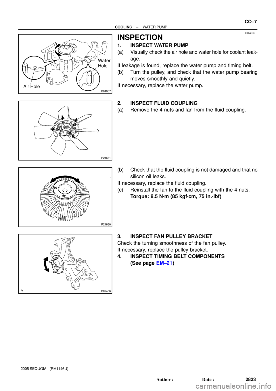
INSPECTION
1. INSPECT WATER PUMP
(a) Visually check the air hole and water hole for coolant leak-
age.
If leakage is found, replace the water pump and timing belt.
(b) Turn the pulley, and check that the water pump bearing
moves smoothly and quietly.
If necessary, replace the water pump.
2. INSPECT FLUID COUPLING
(a) Remove the 4 nuts and fan from the fluid coupling.
(b) Check that the fluid coupling is not damaged and that no
silicon oil leaks.
If necessary, replace the fluid coupling.
(c) Reinstall the fan to the fluid coupling with the 4 nuts.
Torque: 8.5 N´m (85 kgf´cm, 75 in.´lbf)
3. INSPECT FAN PULLEY BRACKET
Check the turning smoothness of the fan pulley.
If necessary, replace the pulley bracket.
4. INSPECT TIMING BELT COMPONENTS
(See page EM±21)
Page 2842 of 4323
CO0UY±03
B07220
CO±18
± COOLINGRADIATOR
2834 Author�: Date�:
2005 SEQUOIA (RM1146U)
INSTALLATION
1. INSTALL NO.1 FAN SHROUD
Install the No.1 fan shroud with the 4 bolts.
Torque: 5.0 N´m (50 kgf´cm, 44 in.´lbf)
2. INSTALL RADIATOR ASSEMBLY
(a) Set the radiator bracket hooks to the radiator support
holes.
(b) Install the 4 bolts.
Torque: 12 N´m (120 N´m, 9 ft´lbf)
3. INSTALL NO.2 FAN SHROUD
Install the No.2 fan shroud with the 2 clips.
4. CONNECT A/T OIL COOLER HOSES TO RADIATOR
5. CONNECT UPPER RADIATOR HOSE TO RADIATOR
6. CONNECT LOWER RADIATOR HOSE TO RADIATOR
7. CONNECT RADIATOR RESERVOIR HOSE TO RADIA-
TOR
8. FILL WITH ENGINE COOLANT
9. START ENGINE AND CHECK FOR ENGINE COOLANT
LEAKS
10. RECHECK ENGINE COOLANT LEVEL
11. INSTALL ENGINE UNDER COVER
Page 2843 of 4323
:
TEMPERATURE RANGE ANTICIPATED BEFORE NEXT OIL CHANGE5W±30°C °F
±20
±290
±1820
±740
460
1680
27100
38
LU0GV±05
B07230
Oil Pressure Gauge
Oil Pressure Switch")
B16233
Recommended Viscosity (SAE):
TEMPERATURE RANGE ANTICIPATED BEFORE NEXT OIL CHANGE5W±30°C °F
±20
±290
±1820
±740
460
1680
27100
38
LU0GV±05
B07230
Oil Pressure Gauge
Oil Pressure Switch
P08343
Adhesive
± LUBRICATIONOIL AND FILTER
LU±1
2835 Author�: Date�:
2005 SEQUOIA (RM1146U)
OIL AND FILTER
INSPECTION
1. CHECK ENGINE OIL QUALITY
Check the oil for deterioration, entry of water, discoloring or thin-
ning.
If the quality is visibly poor, replace the oil.
Oil grade:
API grade SL Energy±Conserving or ILSAC multi-
grade engine oil.
2. CHECK ENGINE OIL LEVEL
The oil level should be between the ºLº and ºFº marks on the dip-
stick.
If low, check for leakage and add oil up to the ºFº mark.
NOTICE:
Do not fill with engine oil above the ºFº mark.
3. REMOVE ENGINE UNDER COVER
4. REMOVE OIL PRESSURE SWITCH
5. INSTALL OIL PRESSURE GAUGE
6. WARM UP ENGINE
Allow the engine to warm up to normal operating temperature.
7. CHECK OIL PRESSURE
Oil pressure:
At idle29 kPa (0.3 kgf/cm2, 4.2 psi) or more
At 3,000 rpm294 ± 588 kPa (3.0 ± 6.0 kgf/cm2, 43 ± 85 psi)
8. REMOVE OIL PRESSURE GAUGE
9. REINSTALL OIL PRESSURE SWITCH
(a) Apply adhesive to 2 or 3 threads of the oil pressure switch.
Adhesive:
Part No. 08833±00080, THREE BOND 1344, LOCTITE
242 or equivalent
(b) Reinstall the oil pressure switch.
10. START ENGINE, AND CHECK FOR ENGINE OIL
LEAKS
11. REINSTALL ENGINE UNDER COVER