Page 2700 of 4323

(c) Inspect the piston ring end gap.
(1) Insert the piston ring into t")
A04872
105 mm
EM7639
A04048
60°C
Z14454
± ENGINE MECHANICALCYLINDER BLOCK
EM±113
2692 Author�: Date�:
2005 SEQUOIA (RM1146U)
(c) Inspect the piston ring end gap.
(1) Insert the piston ring into the cylinder bore.
(2) Using a piston, push the piston ring a little to the bot-
tom of the ring travel, 105 mm (4.13 in.) from the top
of the cylinder block.
(3) Using a feeler gauge, measure the end gap.
Standard end gap:
No.10.300 to 0.400 mm (0.0118 to 0.0157 in.)
No.20.400 to 0.550 mm (0.0157 to 0.0217 in.)
Oil (Side rail)0.130 to 0.380 mm (0.0051 to 0.0150 in.)
Maximum end gap:
No.11.10 mm (0.0433 in.)
No.21.30 mm (0.0512 in.)
Oil (Side rail)0.90 mm (0.0354 in.)
If the end gap is greater than maximum, replace the piston ring.
If the end gap is greater than maximum, even with a new piston
ring, rebore all the 8 cylinders (See page EM±116) or replace
the cylinder block.
(d) Inspect the piston pin fit.
At 60°C (140°F), you should be able to push the piston
pin into the piston pin hole with your thumb.
(e) Using a rod aligner and feeler gauge, check the connect-
ing rod alignment.
(1) Check for bend.
Maximum bend:
0.05 mm (0.0020 in.) per 100 mm (3.94 in.)
If bend is greater than maximum, replace the connecting rod as-
sembly.
Page 2701 of 4323

(2) Check for twist.
Maximum twist:
0.15 mm (0.0059 in.) per 100 mm")
Z14455
EM6525
EM0227
A04223
Tension
Portion
EM±114
± ENGINE MECHANICALCYLINDER BLOCK
2693 Author�: Date�:
2005 SEQUOIA (RM1146U)
(2) Check for twist.
Maximum twist:
0.15 mm (0.0059 in.) per 100 mm (3.94 in.)
If twist is greater than maximum, replace the connecting rod as-
sembly.
(f) Inspect the piston pin oil clearance.
(1) Using a caliper gauge, measure the inside diameter
of the connecting rod bushing.
Bushing inside diameter:
22.005 to 22.014 mm (0.8663 to 0.8667 in.)
(2) Using a micrometer, measure the piston pin diame-
ter.
Piston pin diameter:
21.997 to 22.009 mm (0.8660 to 0.8664 in.)
(3) Subtract the piston pin diameter measurement from
the bushing inside diameter measurement.
Standard oil clearance:
0.005 to 0.011 mm (0.0002 to 0.0004 in.)
Maximum oil clearance: 0.05 mm (0.0020 in.)
If the oil clearance is greater than maximum, replace the bush-
ing. If necessary, replace the piston and piston pin as a set.
(g) Using vernier calipers, measure the tension portion of the
connecting rod bolt.
Standard diameter:
7.200 to 7.300 mm (0.2835 to 0.2874 in.)
Minimum diameter: 7.00 mm (0.2756 in.)
If the diameter is less than the minimum, replace the bolt.
Page 2702 of 4323
A05121
A05854A05122A05169
± ENGINE MECHANICALCYLINDER BLOCK
EM±115
2694 Author�: Date�:
2005 SEQUOIA (RM1146U)
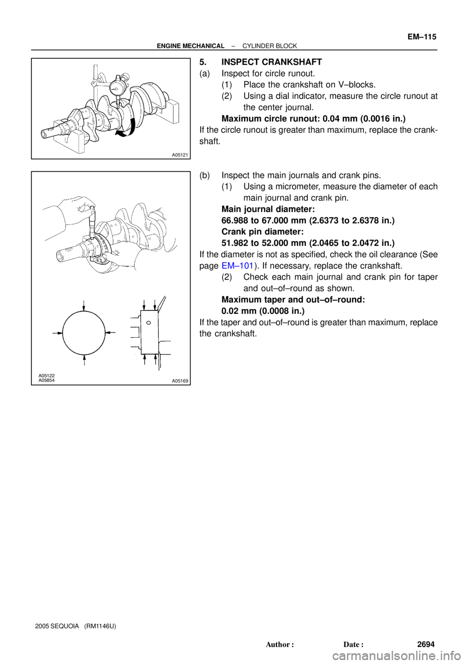
5. INSPECT CRANKSHAFT
(a) Inspect for circle runout.
(1) Place the crankshaft on V±blocks.
(2) Using a dial indicator, measure the circle runout at
the center journal.
Maximum circle runout: 0.04 mm (0.0016 in.)
If the circle runout is greater than maximum, replace the crank-
shaft.
(b) Inspect the main journals and crank pins.
(1) Using a micrometer, measure the diameter of each
main journal and crank pin.
Main journal diameter:
66.988 to 67.000 mm (2.6373 to 2.6378 in.)
Crank pin diameter:
51.982 to 52.000 mm (2.0465 to 2.0472 in.)
If the diameter is not as specified, check the oil clearance (See
page EM±101). If necessary, replace the crankshaft.
(2) Check each main journal and crank pin for taper
and out±of±round as shown.
Maximum taper and out±of±round:
0.02 mm (0.0008 in.)
If the taper and out±of±round is greater than maximum, replace
the crankshaft.
Page 2704 of 4323

(d) Using a pin hole grinder, hone the bushing to obtain the")
P20667
P20668
A04868
A04867
SST
A04858Cut Position
± ENGINE MECHANICALCYLINDER BLOCK
EM±117
2696 Author�: Date�:
2005 SEQUOIA (RM1146U)
(d) Using a pin hole grinder, hone the bushing to obtain the
standard specified clearance (See page EM±101) be-
tween the bushing and piston pin.
(e) Check the piston pin fit at normal room temperature. Coat
the piston pin with engine oil, and push it into the connect-
ing rod with your thumb.
3. REPLACE CRANKSHAFT FRONT OIL SEAL (See
page LU±13)
4. REPLACE CRANKSHAFT REAR OIL SEAL
HINT:
There are 2 methods ((a) and (b)) to replace the oil seal.
(a) If the rear oil seal retainer is removed from the cylinder
block:
(1) Using a screwdriver and hammer, tap out the oil
seal.
(2) Using SST and a hammer, tap in a new oil seal until
its surface is flush with the rear oil seal retainer
edge.
SST 09223±56010
(3) Apply MP grease to the oil seal lip.
(b) If the rear oil seal retainer is installed to the cylinder block:
(1) Using a knife, cut off the oil seal lip.
(2) Using a screwdriver, pry out the oil seal.
NOTICE:
Be careful not to damage the crankshaft. Tape the screw-
driver tip.
Page 2709 of 4323

Front
LH
Piston
RH
PistonFront
Front Mark
(2 Cavities)
EM±122
± ENGINE MECHANICALCYLINDER BLOCK
2701 Aut")
A05095
1
248
6
3
5
9
7
10
A05094
Front
Painted
Mark90° 90°
A23371
Front Mark
(1 Cavity)
Front
LH
Piston
RH
PistonFront
Front Mark
(2 Cavities)
EM±122
± ENGINE MECHANICALCYLINDER BLOCK
2701 Author�: Date�:
2005 SEQUOIA (RM1146U)
(a) Apply a light coat of engine oil to the threads and under
the main bearing cap bolts.
(b) Install and uniformly tighten the 10 main bearing cap bolts
in several steps, in the sequence shown.
Torque: 27 N´m (275 kgf´cm, 20 ft´lbf)
If any of the main bearing cap bolts does not meet the torque
specification, replace the main bearing cap bolt.
(c) Mark the front of the main bearing cap bolt with paint.
(d) Retighten the main bearing cap bolts by 90° in the numer-
ical order shown.
(e) Check that the painted mark is now at a 90° angle to the
front.
(f) Check that the crankshaft turns smoothly.
9. CHECK CRANKSHAFT THRUST CLEARANCE
(See page EM±101)
10. INSTALL PISTON AND CONNECTING ROD AS-
SEMBLIES
Using a piston ring compressor, push correctly the numbered
piston and connecting rod assemblies into each cylinder with
the front mark of the piston facing forward.
NOTICE:
The shape of the piston differs for the LH and RH banks.
The LH piston is marked with 1 cavity and º2º, the RH pis-
ton with 2 cavities and º2º.
Page 2710 of 4323

RH Bank LH Bank
Front
Outside Mark
(Protrusion)
A05101
A05099
Painted
Mark Front90°
90°
± ENGINE MECHANICALCYLINDER BLOCK
EM±123
2702 Auth")
A05106
A05107A05108A05174
Front
Outside Mark
(Protrusion)
RH Bank LH Bank
Front
Outside Mark
(Protrusion)
A05101
A05099
Painted
Mark Front90°
90°
± ENGINE MECHANICALCYLINDER BLOCK
EM±123
2702 Author�: Date�:
2005 SEQUOIA (RM1146U)
11. PLACE CONNECTING ROD CAP ON CONNECTING
ROD
(a) Match the numbered connecting rod cap with the con-
necting rod.
(b) Align the pin groove of the connecting rod cap with the
pins of the connecting rod, and install the connecting rod
cap.
(c) Check that the outside mark of the connecting rod cap is
facing in correct direction.
12. INSTALL CONNECTING ROD CAP BOLTS
HINT:
�The connecting rod cap bolts are tightened in 2 progres-
sive steps (steps (b) and (d)).
�If any one of the connecting rod cap bolts is broken or de-
formed, replace it.
(a) Apply a light coat of engine oil on the threads and under
the heads of the connecting rod cap bolts.
(b) Install and alternately tighten the 2 connecting rod cap
bolts in several passes.
Torque: 24.5 N´m (250 kgf´cm, 18 ft´lbf)
If any one of the connecting rod cap bolts does not meet the
torque specification, replace the connecting rod cap bolts.
(c) Mark the front of the connecting cap bolt with paint.
(d) Retighten the cap bolts by 90° as shown.
(e) Check that the painted mark is now at a 90° angle to the
front.
(f) Check that the crankshaft turns smoothly.
13. CHECK CONNECTING ROD THRUST CLEARANCE
(See page EM±101)
Page 2743 of 4323

SFI SYSTEM
PRECAUTION
HINT:
All DTCs retained in the ECM will be erased when the negative
(±) terminal cable is removed")
SF1XD±01
± SFISFI SYSTEM
SF±1
2735 Author�: Date�:
2005 SEQUOIA (RM1146U)
SFI SYSTEM
PRECAUTION
HINT:
All DTCs retained in the ECM will be erased when the negative
(±) terminal cable is removed from the battery.
If necessary, read the DTC before removing the negative (±)
terminal cable from the battery.
1. BEFORE WORKING ON FUEL SYSTEM,
DISCON-
NECT CABLE FROM NEGATIVE (±) BATTERY TERMI-
NAL
2. DO NOT SMOKE OR WORK NEAR AN OPEN FLAME
WHEN WORKING ON FUEL SYSTEM
3. KEEP GASOLINE AWAY FROM RUBBER OR
LEATH-
ER PARTS
4. MAINTENANCE PRECAUTIONS
(a) To prevent engine misfire, these precautions should be
taken.
(1) Check the battery terminals are proper connected.
(2) After repair, check that the ignition coil terminals
and all other ignition system lines are reconnected
securely.
(3) When cleaning the engine compartment, be espe-
cially careful to protect the electrical system from
water.
(b) Observe the following when handling the air fuel ratio
sensors and oxygen sensor.
(1) Do not drop the sensor or hit it against another ob-
ject.
(2) The sensor should be free from any contact with wa-
ter.
5. IF VEHICLE IS EQUIPPED WITH MOBILE RA-
DIO
SYSTEM (HAM, CB, ETC.)
If the vehicle is equipped with a mobile communication system,
refer to the precaution in the IN section.
6. AIR INDUCTION SYSTEM
(a) Removal of the engine oil dipstick, oil filler cap, PCV hose,
may break the engine.
(b) Disconnection, looseness or cracks in the parts of the air
induction system between the throttle body and cylinder
head may result in air suction and break the engine.
7. ELECTRONIC CONTROL SYSTEM
(a) Before removing SFI wiring connectors, terminals, first
disconnect the power by turning the ignition switch off or
disconnecting the negative (±) terminal cable from the
battery.
HINT:
Be sure to check DTCs before disconnecting the negative (±)
terminal cable from the battery.
Page 2745 of 4323

B16499
Fulcrum
Length
30 cm
SST
B02714
CORRECT
WRONG
Delivery Pipe O±Ring
B04939
Delivery
Pipe
Intake
Manifold O±Ring
Grommet
Injector
Insulator
B17532
Quick Type
Disconnect
B11684
Quick Type
Push
Pull
± SFISFI SYSTEM
SF±3
2737 Author�: Date�:
2005 SEQUOIA (RM1146U)
(3) Using SST, tighten the union bolt to the specified
torque.
SST 09612±24014 (09617±24011)
Torque:
33 N´m (340 kgf´cm, 24 ft´lbf) for use with SST
39 N´m (400 kgf´cm, 29 ft´lbf)
HINT:
Use a torque wrench with a fulcrum length of 30 cm (11.81 in.).
(c) Observe the following precautions when removing or
installing the injectors.
(1) Never reuse the O±ring.
(2) When placing a new O±ring on the injector, take
care not to damage it in any way.
(3) Coat a new O±ring with spindle oil or gasoline be-
fore installing. Never use engine, gear or brake oil.
(d) Install the injector to the delivery pipe and intake manifold
as shown in the illustration.
Before installing the injector, apply spindle oil or gasoline
on the place where the delivery pipe or the intake man-
ifold touches the O±ring of the injector.
(e) Observe the following when disconnecting the fuel tube
connector (quick type):
(1) Check if there is any dirt in the pipe and around the
connector before disconnecting the fuel tube con-
nector. If necessary, clean the dirt away.
(2) Disconnect the fuel pipe clamp from the connector.
(3) Be sure to disconnect them by hand.
(4) When the connector and the pipe are stuck, push
and pull the connector. Then disconnect and pull it
out. Do not use any tools at this time.
(5) Check if there is any dirt or other foreign matter on
the seal surface of the disconnected pipe. If neces-
sary, clean the dirt away.
(6) Do not damage the disconnected pipe and connec-
tor and prevent intrusion of foreign objects by cover-
ing them with a plastic bag.