Page 1819 of 4323

± DIAGNOSTICSCOMBINATION METER SYSTEM
DI±1617
1811 Author�: Date�:
2005 SEQUOIA (RM1146U)
(c) Reconnect the C5 and C6 connectors.
(d) Measure the voltage of each terminal of the wire harness side connector.
Standard:
Terminals No.Wiring ColorTerminal DescriptionConditionSpecified Condition
C5±1 ± Body groundR±B ± Body
groundParking brake signalParking brake warning light ON6.7 to 12 V
C5±1 ± Body groundR±B ± Body
groundParking brake signalParking brake warning light OFFBelow 1 V
C5±2 ± Body groundLG±R ± Body
groundCRUISE signalCRUISE indicator light ONBelow 1 V
C5±2 ± Body groundLG±R ± Body
groundCRUISE signalCRUISE indicator light OFF10 to 14 V
C5±3 ± Body groundB ± Body groundIgnition switch signal
(Start)Ignition switch OFFBelow 1 V
C5±3 ± Body groundB ± Body groundIgnition switch signal
(Start)Ignition switch START10 to 14 V
C5±4 ± Body groundG±Y ± Body
groundSeat belt condition signal
(Driver side)D±BELT indicator light ONBelow 1 V
C5±4 ± Body groundG±Y ± Body
groundSeat belt condition signal
(Driver side)D±BELT indicator light OFF10 to 14 V
C5±13 ± Body groundLG±R ± Body
groundWasher level signalWASH LVL indicator light ONBelow 1 V
C5±13 ± Body groundLG±R ± Body
groundWasher level signalWASH LVL indicator light OFF10 to 14 V
C5±14 ± Body groundL±O ± Body
groundO/D OFF indicator signalO/D OFF indicator light ONBelow 1 V
C5±14 ± Body groundL±O ± Body
groundO/D OFF indicator signalO/D OFF indicator light OFF10 to 14 V
C5±15 (*1) ± Body groundY±R ± Body
groundA/T oil temperature signalA/T OIL TEMP. warning light ONBelow 1 V
C5±15 (*1) ± Body groundY±R ± Body
groundA/T oil temperature signalA/T OIL TEMP. warning light OFF10 to 14 V
C5±16 ± Body groundLG±B ± Body
groundSecurity indicator light
signal (Engine immobilizer
system)
Security indicator light ON10 to 14 V
C5±16 ± Body groundLG±B ± Body
groundSecurity indicator light
signal (Engine immobilizer
system)
Security indicator light OFFBelow 1 V
C5±17 ± Body groundGR ± Body
groundSecurity indicator light
signal (Theft deterrent
system)
Security indicator light ON10 to 14 V
C5±17 ± Body groundGR ± Body
groundSecurity indicator light
signal (Theft deterrent
system)
Security indicator light OFFBelow 1 V
C5±18 ± Body groundV±W ± Body
groundCHECK ENGINE signalCHECK ENGINE warning light ONBelow 1 V
C5±18 ± Body groundV±W ± Body
groundCHECK ENGINE signalCHECK ENGINE warning light OFF10 to 14 V
C5±19 ± Body groundG±B ± Body
groundA/T shift position signal
(L)A/T L indicator OFFBelow 1 V
Page 1825 of 4323
I27707
C6±21
C6±8
(*4) C5±15
C5±18
C5±2
C5±14
C5±19
C5±13
C6±1
C6±2
C6±3
C5±20ABS
CHARGE
A/T OIL TEMP
CHECK E/G
4LO O/D OFF
A/T L
WASHER
SLIP
VSC OFF
VSC TRAC
4HI CRUISE
ONE STEP
DIMMERC6±24
C6±5
C6±6
C6±4
C5±40TIRE PRS
CTR DIFF LOCK
RSCA OFF
SECURITY
P
R
NC5±16
C5±17
C5±34
C5±35
C5±36
C5±37
C5±38
C5±39
C6±17 (*5)
C6±18 (*6)
C5±33
C6±19 TURN (L) TURN (R) BEAM3
2 D
*4: 4WD *5: w/o Daytime Running Light *6: w/ Daytime Running LightONE STEP
DIMMERRSCA OFF
± DIAGNOSTICSCOMBINATION METER SYSTEM
DI±1623
1817 Author�: Date�:
2005 SEQUOIA (RM1146U)
Page 1857 of 4323
± DIAGNOSTICSCOMBINATION METER SYSTEM
DI±1655
1849 Author�: Date�:
2005 SEQUOIA (RM1146U)
INSPECTION PROCEDURE
HINT:
Start the inspection from step 1 when using the hand±held tester and start from step 3 when not using the
hand±held tester.
1 Perform active test by hand±held tester.
PREPARATION:
(a) Connect the hand±held tester to the DLC3.
(b) Turn the ignition switch ON, and push the hand±held tester main switch ON.
CHECK:
From the display on the tester, perform the ºACTIVE TESTº.
METER:
ItemTest DetailsDiagnostic Note
OIL PRESS METERHIGH, 3/4, 1/2, 1/4, LOW (OFF)Confirm that the vehicle is stopped and engine is
idling.
OK:
Oil pressure receiver gauge readings change according to hand±held tester operation.
NG Replace combination meter
(See page IN±35).
OK
Page 1858 of 4323

I01278
DI±1656
± DIAGNOSTICSCOMBINATION METER SYSTEM
1850 Author�: Date�:
2005 SEQUOIA (RM1146U)
2 Read value of hand±held tester.
PREPARATION:
(a) Connect the hand±held tester to the DLC3.
(b) Turn the ignition switch ON, and push the hand±held tester main switch ON.
CHECK:
Operate the hand±held tester according to the steps on the display and select ºDATA LISTº.
METER:
ItemMeasurement Item /
Range (Display)Normal ConditionDiagnostic Note
OIL GAUGEOil Gauge /
Min.: 0 Max.: 255Tester indication changes accord-
ing to the oil pressure receiver
gauge angle.
OK:
Oil pressure displayed on the tester is almost the same as the actual oil pressure.
OK Replace combination meter.
(See page IN±35)
NG
3 Inspect oil pressure sender gauge.
PREPARATION:
Disconnect the connector from the oil pressure sender.
CHECK:
(a) Check that no continuity exists between the terminal and
ground with the engine stopped.
(b) Check that continuity exists between the terminal and
ground with the engine running.
HINT:
Oil pressure should be over 24.5 kPa (0.25 kgf/cm
2, 3.55 psi).
OK:
When engine is stopped:
No continuity
When engine is running:
Continuity
NG Replace oil pressure sender gauge.
OK
Page 1859 of 4323
I28569
Combination Meter:
C5±27
I28581
Oil Pressure Sender Gauge
Wire Harness:
O2
± DIAGNOSTICSCOMBINATION METER SYSTEM
DI±1657
1851 Author�: Date�:
2005 SEQUOIA (RM1146U)
4 Check harness and connector (Oil pressure sender gauge ± combination meter).
PREPARATION:
Disconnect the C5 connector of the combination meter.
CHECK:
Measure the resistance according to the value(s) in the table
below.
OK:
Tester ConnectionSpecified Condition
C5±27 ± O2±1Below 1 W
C5±27 ± Body ground10 kW or higher
NG Repair or replace harness or connector.
OK
Replace combination meter
(See page IN±35).
Page 2590 of 4323

EM0KR±10
A04458
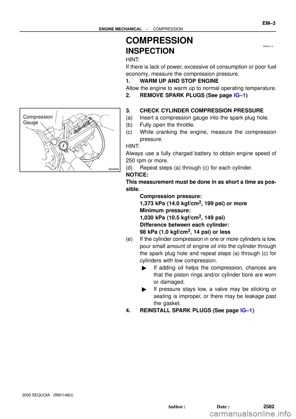
Compression
Gauge
± ENGINE MECHANICALCOMPRESSION
EM±3
2582 Author�: Date�:
2005 SEQUOIA (RM1146U)
COMPRESSION
INSPECTION
HINT:
If there is lack of power, excessive oil consumption or poor fuel
economy, measure the compression pressure.
1. WARM UP AND STOP ENGINE
Allow the engine to warm up to normal operating temperature.
2. REMOVE SPARK PLUGS (See page IG±1)
3. CHECK CYLINDER COMPRESSION PRESSURE
(a) Insert a compression gauge into the spark plug hole.
(b) Fully open the throttle.
(c) While cranking the engine, measure the compression
pressure.
HINT:
Always use a fully charged battery to obtain engine speed of
250 rpm or more.
(d) Repeat steps (a) through (c) for each cylinder.
NOTICE:
This measurement must be done in as short a time as pos-
sible.
Compression pressure:
1,373 kPa (14.0 kgf/cm
2, 199 psi) or more
Minimum pressure:
1,030 kPa (10.5 kgf/cm
2, 149 psi)
Difference between each cylinder:
98 kPa (1.0 kgf/cm
2, 14 psi) or less
(e) If the cylinder compression in one or more cylinders is low,
pour small amount of engine oil into the cylinder through
the spark plug hole and repeat steps (a) through (c) for
cylinders with low compression.
�If adding oil helps the compression, chances are
that the piston rings and/or cylinder bore are worn
or damaged.
�If pressure stays low, a valve may be sticking or
seating is improper, or there may be leakage past
the gasket.
4. REINSTALL SPARK PLUGS (See page IG±1)
Page 2591 of 4323

EM0KS±09
A23300
A23301
EM±4
± ENGINE MECHANICALVALVE CLEARANCE
2583 Author�: Date�:
2005 SEQUOIA (RM1146U)
VALVE CLEARANCE
INSPECTION
HINT:
Inspect and adjust the valve clearance when the engine is cold.
1. REMOVE BATTERY CLAMP COVER
2. REMOVE THROTTLE BODY COVER
3. REMOVE AIR CLEANER AND INTAKE AIR CONNEC-
TOR ASSEMBLY
4. REMOVE NO.3 TIMING BELT COVERS
(See page EM±16)
5. REMOVE IGNITION COILS (See page IG±5)
6. REMOVE RH CYLINDER HEAD COVER
Remove the 9 bolts, seal washers and cylinder head cover.
7. REMOVE LH CYLINDER HEAD COVER
(a) Remove the oil dipstick for the transmission.
(b) Disconnect the PCV hose.
(c) Disconnect the engine wire clamp from the wire bracket
on the cylinder head cover.
(d) Remove the 9 bolts, 9 seal washers and cylinder head
cover.
8. SET NO.1 CYLINDER TO TDC/COMPRESSION
(a) Turn the crankshaft pulley, and align its groove with timing
mark º0º of the No.1 timing belt cover.
(b) Check that the timing marks of the camshaft timing pul-
leys and timing belt rear plates are aligned.
If not, turn the crankshaft 1 revolution (360°) and align the mark
as above.
Page 2593 of 4323

A02213
EM±6
± ENGINE MECHANICALVALVE CLEARANCE
2585 Author�: Date�:
2005 SEQUOIA (RM1146U)
10. ADJUST VALVE CLEARANCE
(a) Remove the timing belt. (See page EM±16)
(b) Remove the camshafts. (See page EM±36)
(c) Remove the valve lifter and adjusting shim.
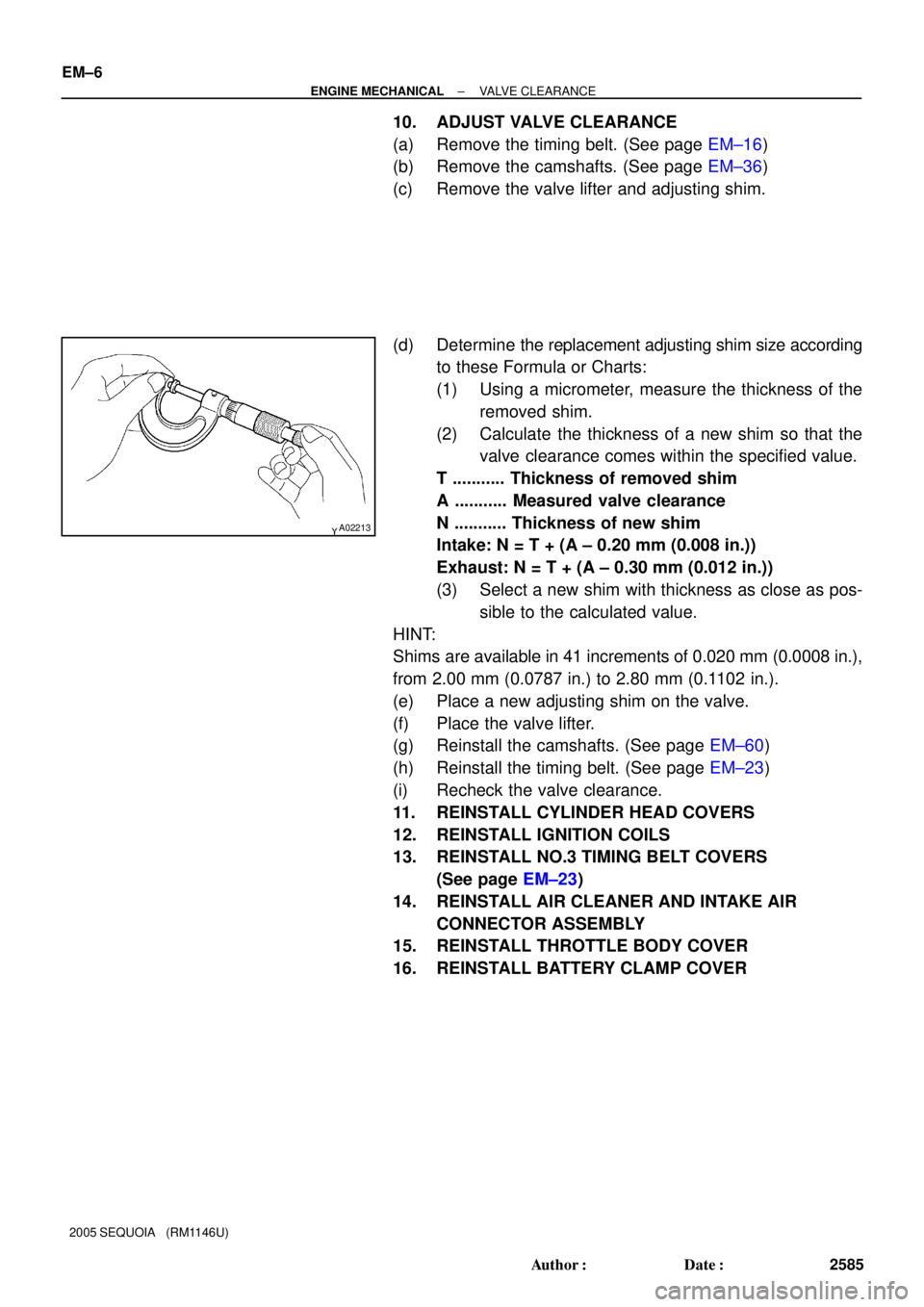
(d) Determine the replacement adjusting shim size according
to these Formula or Charts:
(1) Using a micrometer, measure the thickness of the
removed shim.
(2) Calculate the thickness of a new shim so that the
valve clearance comes within the specified value.
T ........... Thickness of removed shim
A ........... Measured valve clearance
N ........... Thickness of new shim
Intake: N = T + (A ± 0.20 mm (0.008 in.))
Exhaust: N = T + (A ± 0.30 mm (0.012 in.))
(3) Select a new shim with thickness as close as pos-
sible to the calculated value.
HINT:
Shims are available in 41 increments of 0.020 mm (0.0008 in.),
from 2.00 mm (0.0787 in.) to 2.80 mm (0.1102 in.).
(e) Place a new adjusting shim on the valve.
(f) Place the valve lifter.
(g) Reinstall the camshafts. (See page EM±60)
(h) Reinstall the timing belt. (See page EM±23)
(i) Recheck the valve clearance.
11. REINSTALL CYLINDER HEAD COVERS
12. REINSTALL IGNITION COILS
13. REINSTALL NO.3 TIMING BELT COVERS
(See page EM±23)
14. REINSTALL AIR CLEANER AND INTAKE AIR
CONNECTOR ASSEMBLY
15. REINSTALL THROTTLE BODY COVER
16. REINSTALL BATTERY CLAMP COVER