2001 NISSAN X-TRAIL belt
[x] Cancel search: beltPage 3248 of 3833
EI-28
FLOOR TRIM
FLOOR TRIM
PFP:74902
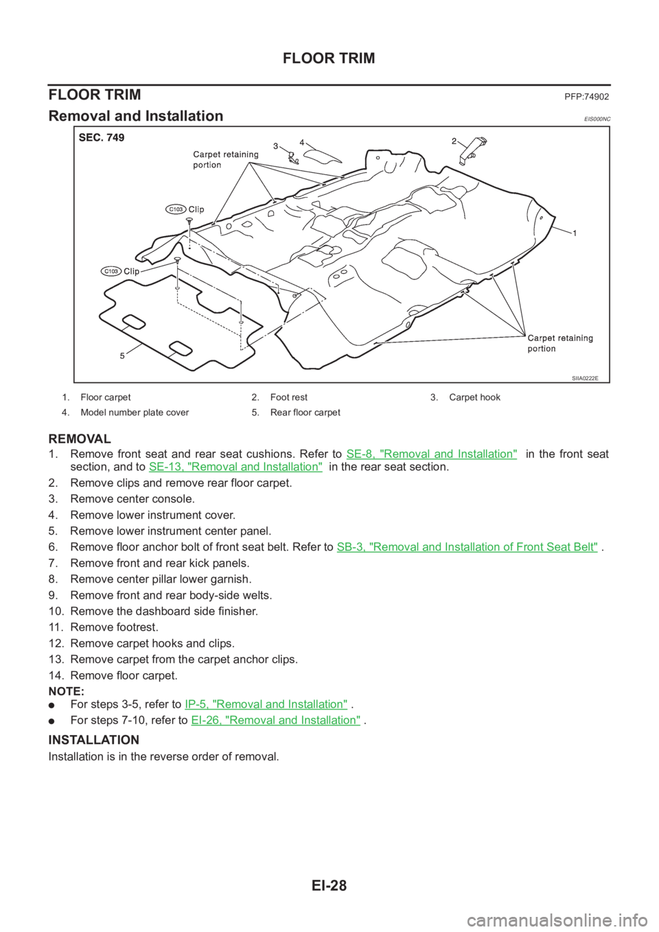
Removal and InstallationEIS000NC
REMOVAL
1. Remove front seat and rear seat cushions. Refer to SE-8, "Removal and Installation" in the front seat
section, and to SE-13, "
Removal and Installation" in the rear seat section.
2. Remove clips and remove rear floor carpet.
3. Remove center console.
4. Remove lower instrument cover.
5. Remove lower instrument center panel.
6. Remove floor anchor bolt of front seat belt. Refer to SB-3, "
Removal and Installation of Front Seat Belt" .
7. Remove front and rear kick panels.
8. Remove center pillar lower garnish.
9. Remove front and rear body-side welts.
10. Remove the dashboard side finisher.
11. Remove footrest.
12. Remove carpet hooks and clips.
13. Remove carpet from the carpet anchor clips.
14. Remove floor carpet.
NOTE:
●For steps 3-5, refer to IP-5, "Removal and Installation" .
●For steps 7-10, refer to EI-26, "Removal and Installation" .
INSTALLATION
Installation is in the reverse order of removal.
SIIA0222E
1. Floor carpet 2. Foot rest 3. Carpet hook
4. Model number plate cover 5. Rear floor carpet
Page 3251 of 3833
IP-1
INSTRUMENT PANEL
I BODY
CONTENTS
C
D
E
F
G
H
J
K
L
M
SECTION
A
B
IP
INSTRUMENT PANEL
PRECAUTIONS .......................................................... 2
Precautions for Supplemental Restraint System
(SRS) “AIR BAG” and “SEAT BELT PRE-TEN-
SIONER” .................................................................. 2
Precautions .............................................................. 2
INSTRUMENT PANEL ASSEMBLY ........................... 3
Component Parts Drawing ....................................... 3
Removal and Installation .......................................... 5
TABLE OF WORK ITEM ....................................... 5
FRONT SPEAKER GRILLE .................................. 6
INSTRUMENT FINISHER ..................................... 6
CUP HOLDER ....................................................... 6
CLUSTER LID A ................................................... 6
COMBINATION METER ....................................... 6
POCKET ............................................................... 6
STEERING COLUMN COVER ............................. 6
INSTRUMENT LOWER DRIVER PANEL ............. 7
MIRROR CONTROL SWITCH .............................. 7
GPS ANTENNA .................................................... 7
CLUSTER LID C ................................................... 7CLUSTER LID FINISHER ..................................... 7
AUDIO UNIT AND POCKET ................................. 7
HEATER CONTROL FINISHER ............................ 8
CD AUTO–CHANGER AND POCKET .................. 8
HEATER CONTROLLER ....................................... 8
A/T OR M/T FINISHER ......................................... 8
CONSOLE MASK AND CENTER CONSOLE ....... 8
LOWER INSTRUMENT COVER ........................... 8
INSTRUMENT LOWER CENTER PANEL ............ 8
GLOVE BOX ......................................................... 9
LOWER INSTRUMENT PANEL ............................ 9
GLOVE BOX COVER ............................................ 9
FRONT PASSENGER AIR BAG MODULE ........... 9
INSTRUMENT REINFORCEMENT ....................... 9
INSTRUMENT MASK ............................................ 9
FRONT PILLAR GARNISH ................................... 9
INSTRUMENT PANEL .......................................... 9
Disassembly and Assembly .................................... 10
CONSOLE BOX ASSEMBLY .............................. 10
Page 3252 of 3833
IP-2
PRECAUTIONS
PRECAUTIONS
PFP:00001
Precautions for Supplemental Restraint System (SRS) “AIR BAG” and “SEAT
BELT PRE-TENSIONER”
EIS0046I
The Supplemental Restraint System such as “AIR BAG” and “SEAT BELT PRE-TENSIONER”, used along
with a front seat belt, helps to reduce the risk or severity of injury to the driver and front passenger for certain
types of collision. Information necessary to service the system safely is included in the SRS and SB section of
this Service Manual.
WARNING:
●To avoid rendering the SRS inoperative, which could increase the risk of personal injury or death
in the event of a collision which would result in air bag inflation, all maintenance must be per-
formed by an authorized NISSAN/INFINITI dealer.
●Improper maintenance, including incorrect removal and installation of the SRS, can lead to per-
sonal injury caused by unintentional activation of the system. For removal of Spiral Cable and Air
Bag Module, see the SRS section.
●Do not use electrical test equipment on any circuit related to the SRS unless instructed to in this
Service Manual. SRS wiring harnesses can be identified by yellow and/or orange harness connec-
tors.
Precautions EIS001NZ
●Disconnect both battery cables in advance.
●Disconnect air bag system line in advance.
●Never tamper with or force air bag lid open, as this may adversely affect air bag performance.
●Be careful not to scratch pad and other parts.
●When removing or disassembling any part, be careful not to damage or deform it. Protect parts, which
may get in the way with cloth.
●When removing parts with a screwdriver or other tool, protect parts by wrapping them with vinyl or tape.
●Keep removed parts protected with cloth.
●If a clip is deformed or damaged, replace it.
●If an unreusable part is removed, replace it with a new one.
●Tighten bolts and nuts firmly to the specified torque.
●After re-assembly has been completed, make sure each part functions correctly.
●Remove stains in the following way.
Water-soluble stains:
Dip a soft cloth in warm water, and then squeeze it tightly. After wiping the stain, wipe with a soft dry cloth.
Oil stain:
Dissolve a synthetic detergent in warm water (density of 2 to 3% or less), dip the cloth, then clean off the stain
with the cloth. Next, dip the cloth in fresh water and squeeze it tightly. Then clean off the detergent completely.
Then wipe the area with a soft dry cloth.
●Do not use any organic solvent, such as thinner or benzine.
Page 3261 of 3833
SE-1
SEAT
I BODY
CONTENTS
C
D
E
F
G
H
J
K
L
M
SECTION
A
B
SE
SEAT
PRECAUTIONS .......................................................... 2
Service Notice .......................................................... 2
Precautions for Supplemental Restraint System
(SRS) “AIR BAG” and “SEAT BELT PRE-TEN-
SIONER” .................................................................. 2
Precautions .............................................................. 2
HEATED SEAT ........................................................... 3
Wiring Diagram–H/SEAT (LHD MODELS) ............... 3
Wiring Diagram–H/SEAT (RHD MODELS) .............. 5
FRONT SEAT .............................................................. 7
Component Parts Drawing ....................................... 7
Removal and Installation .......................................... 8
Disassembly and Assembly of Seat Back ................ 8
SEAT BACK TRIM (SIDE AIR BAG EQUIPPED
AND GENUINE LEATHER SEAT) ......................... 8
SEAT BACK TRIM [WITHOUT SIDE AIR BAG (EXCEPT GENUINE LEATHER SEAT)] ................ 9
Disassembly and Assembly of Seat Cushion Trim ... 10
REAR SEAT .............................................................. 11
Component Parts Drawing ..................................... 11
STANDARD SEAT ............................................... 11
SEAT WITH ARMREST ....................................... 12
Removal and Installation ........................................ 13
SEAT CUSHION .................................................. 13
IN THE SEAT BACK ............................................ 13
REAR SEAT STRIKER (SIDE) ............................ 14
REAR SEAT CENTER BRACKET ....................... 14
REAR SEAT STRIKER (FLOOR) ........................ 14
Disassembly and Assembly .................................... 14
REAR SEAT BACK LOCK KNOB ........................ 14
ARMREST ........................................................ ... 14
Page 3262 of 3833
SE-2
PRECAUTIONS
PRECAUTIONS
PFP:00001
Service NoticeEIS003UV
●When removing or installing various parts, place a cloth or padding onto the vehicle body to prevent
scratches.
●Handle trim, molding instruments, grille, etc. carefully during removing or installing. Be careful not to oil or
damage them.
●Apply sealing compound where necessary when installing parts.
●When applying sealing compound, be careful that the sealing compound does not protrude from parts.
●When replacing any metal parts (for example body outer panel, member, etc.), be sure to take rust pre-
vention measures.
Precautions for Supplemental Restraint System (SRS) “AIR BAG” and “SEAT
BELT PRE-TENSIONER”
EIS003UN
The Supplemental Restraint System such as “AIR BAG” and “SEAT BELT PRE-TENSIONER”, used along
with a front seat belt, helps to reduce the risk or severity of injury to the driver and front passenger for certain
types of collision. Information necessary to service the system safely is included in the SRS and SB section of
this Service Manual.
WARNING:
●To avoid rendering the SRS inoperative, which could increase the risk of personal injury or death
in the event of a collision which would result in air bag inflation, all maintenance must be per-
formed by an authorized NISSAN/INFINITI dealer.
●Improper maintenance, including incorrect removal and installation of the SRS, can lead to per-
sonal injury caused by unintentional activation of the system. For removal of Spiral Cable and Air
Bag Module, see the SRS section.
●Do not use electrical test equipment on any circuit related to the SRS unless instructed to in this
Service Manual. SRS wiring harnesses can be identified by yellow and/or orange harness connec-
tors.
Precautions EIS001O8
●When removing or disassembling any part, be careful not to damage or deform it. Protect parts, which
may get in the way with cloth.
●When removing parts with a screwdriver or other tool, protect parts by wrapping them with vinyl or tape.
●Keep removed parts protected with cloth.
●If a clip is deformed or damaged, replace it.
●If an unreusable part is removed, replace it with a new one.
●Tighten bolts and nuts firmly to the specified torque.
●After re-assembly has been completed, make sure each part functions correctly.
●Remove stains in the following way.
Water-soluble stains:
Dip a soft cloth in warm water, and then squeeze it tightly. After wiping the stain, wipe with a soft dry cloth.
Oil stain:
Dissolve a synthetic detergent in warm water (density of 2 to 3% or less), dip the cloth, then clean off the stain
with the cloth. Next, dip the cloth in fresh water and squeeze it tightly. Then clean off the detergent completely.
Then wipe the area with a soft dry cloth.
●Do not use any organic solvent, such as thinner or benzine.
Page 3267 of 3833
FRONT SEAT
SE-7
C
D
E
F
G
H
J
K
L
MA
B
SE
FRONT SEATPFP:87000
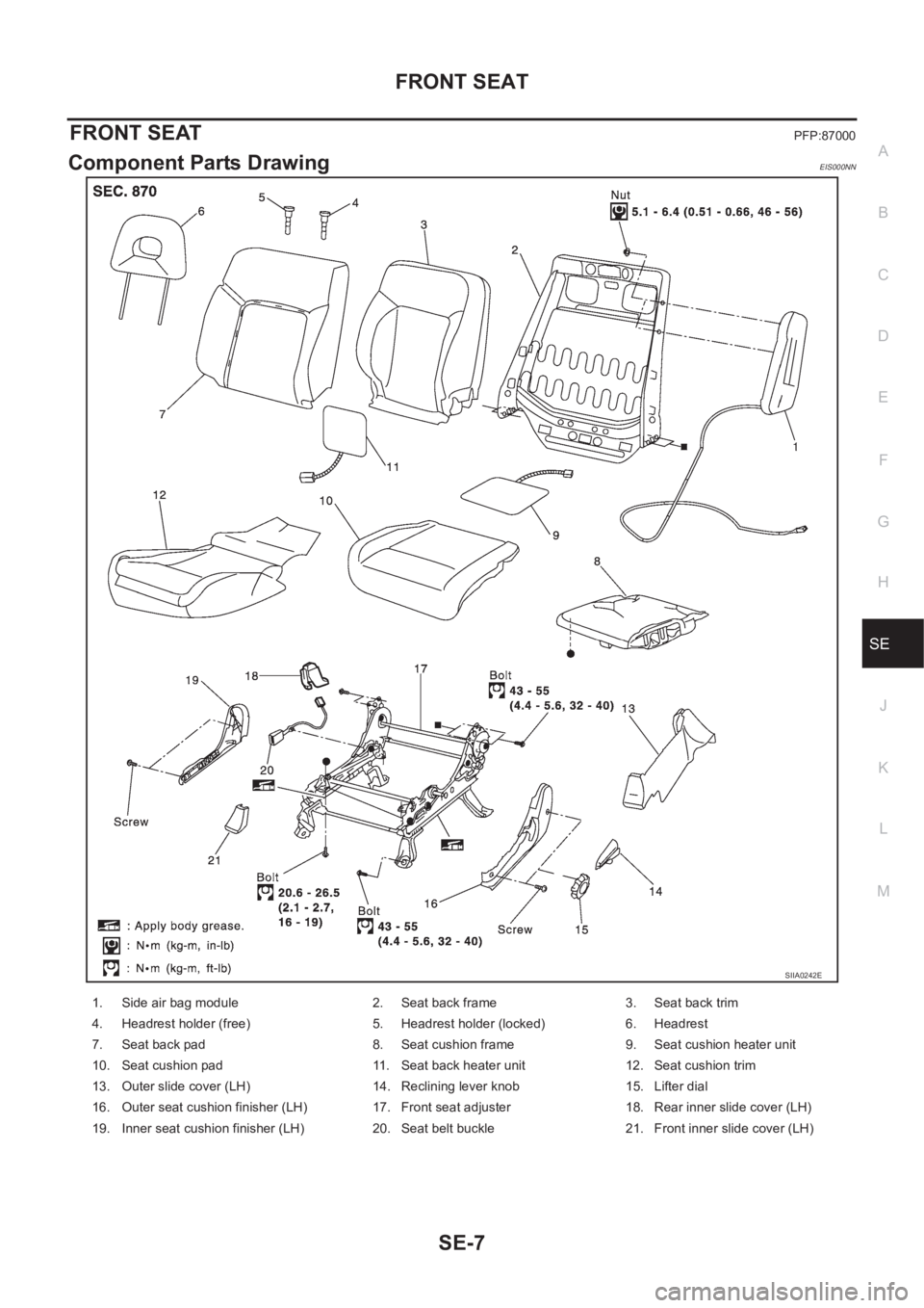
Component Parts DrawingEIS000NN
SIIA0242E
1. Side air bag module 2. Seat back frame 3. Seat back trim
4. Headrest holder (free) 5. Headrest holder (locked) 6. Headrest
7. Seat back pad 8. Seat cushion frame 9. Seat cushion heater unit
10. Seat cushion pad 11. Seat back heater unit 12. Seat cushion trim
13. Outer slide cover (LH) 14. Reclining lever knob 15. Lifter dial
16. Outer seat cushion finisher (LH) 17. Front seat adjuster 18. Rear inner slide cover (LH)
19. Inner seat cushion finisher (LH) 20. Seat belt buckle 21. Front inner slide cover (LH)
Page 3272 of 3833
SE-12
REAR SEAT
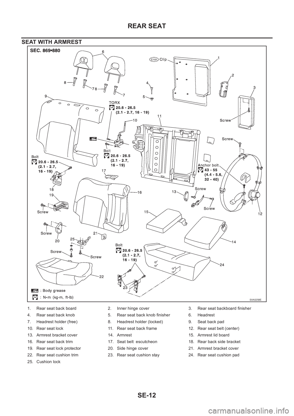
SEAT WITH ARMREST
SIIA0258E
1. Rear seat back board 2. Inner hinge cover 3. Rear seat backboard finisher
4. Rear seat back knob 5. Rear seat back knob finisher 6. Headrest
7. Headrest holder (free) 8. Headrest holder (locked) 9. Seat back pad
10. Rear seat lock 11. Rear seat back frame 12. Rear seat belt (center)
13. Armrest bracket cover 14. Armrest 15. Armrest lid board
16. Rear seat back trim 17. Seat belt escutcheon 18. Rear back side bracket
19. Rear seat lock protector 20. Side hinge cover 21. Armrest bracket cover
22. Rear seat cushion trim 23. Rear seat cushion stay 24. Rear seat cushion pad
25. Cushion lock
Page 3277 of 3833
ATC-1
AUTOMATIC AIR CONDITIONER
J AIR CONDITIONER
CONTENTS
C
D
E
F
G
H
I
K
L
M
SECTION
A
B
AT C
AUTOMATIC AIR CONDITIONER
PRECAUTIONS .......................................................... 4
Precautions for Supplemental Restraint System
(SRS) “AIR BAG” and “SEAT BELT PRE-TEN-
SIONER” .................................................................. 4
Precautions for Working with HFC-134a (R-134a) ..... 4
General Refrigerant Precautions .............................. 5
Lubricant Precautions .............................................. 5
Precautions for Refrigerant Connection ................... 5
FEATURES OF NEW TYPE REFRIGERANT
CONNECTION ...................................................... 6
O-RING AND REFRIGERANT CONNECTION ..... 7
Precautions for Servicing Compressor ..................... 9
Precautions for Service Equipment ........................ 10
RECOVERY/RECYCLING EQUIPMENT ............ 10
ELECTRONIC LEAK DETECTOR ...................... 10
VACUUM PUMP ................................................. 10
MANIFOLD GAUGE SET .................................... 10
SERVICE HOSES ................................................ 11
SERVICE COUPLERS ......................................... 11
REFRIGERANT WEIGHT SCALE ....................... 11
CALIBRATING ACR4 WEIGHT SCALE ............... 11
CHARGING CYLINDER ...................................... 12
Precautions for Leak Detection Dye ....................... 12
IDENTIFICATION ................................................ 12
IDENTIFICATION LABEL FOR VEHICLE ........... 13
Wiring Diagrams and Trouble Diagnosis ................ 13
PREPARATION ......................................................... 14
Special Service Tools ............................................. 14
WITH GASOLINE ENGINE (CWV-615M COM-
PRESSOR) ......................................................... 14
WITH DIESEL ENGINE (DKV-11G COMPRES-
SOR) ................................................................... 14
HFC-134a (R-134a) Service Tools and Equipment ... 15
REFRIGERATION SYSTEM ..................................... 18
Refrigerant Cycle ................................................... 18
REFRIGERANT FLOW ....................................... 18
FREEZE PROTECTION (WITH GASOLINE
ENGINE: CWV-615M COMPRESSOR) .............. 18
Refrigerant System Protection ............................... 18
REFRIGERANT PRESSURE SENSOR (WITH GASOLINE ENGINE: CWV-615M COMPRES-
SOR) ................................................................... 18
DUAL-PRESSURE SWITCH (WITH DIESEL
ENGINE: DKV-11G COMPRESSOR) .................. 18
PRESSURE RELIEF VALVE (WITH GASOLINE
ENGINE: CWV-615M COMPRESSOR) .............. 18
V-6 Variable Displacement Compressor (With Gas-
oline Engine: CWV-615M Compressor) .................. 19
GENERAL INFORMATION ................................. 19
DESCRIPTION .................................................... 20
Component Layout ................................................. 23
LUBRICANT .............................................................. 24
Maintenance of Lubricant Quantity in Compressor ... 24
LUBRICANT ........................................................ 24
LUBRICANT RETURN OPERATION .................. 24
LUBRICANT ADJUSTING PROCEDURE FOR
COMPONENTS REPLACEMENT EXCEPT
COMPRESSOR .................................................. 25
LUBRICANT ADJUSTING PROCEDURE FOR
COMPRESSOR REPLACEMENT ....................... 25
AIR CONDITIONER CONTROL ............................... 27
Overview Air Conditioner LAN Control System ...... 27
System Construction .............................................. 27
OPERATION ........................................................ 27
TRANSMISSION DATA AND TRANSMISSION
ORDER ............................................................... 28
AIR MIX DOOR CONTROL (AUTOMATIC TEM-
PERATURE CONTROL) ..................................... 28
FAN SPEED CONTROL ...................................... 29
INTAKE DOOR CONTROL ................................. 29
OUTLET DOOR CONTROL ................................ 29
MAGNET CLUTCH CONTROL ........................... 29
SELF-DIAGNOSTIC SYSTEM ............................ 29
Overview of Control system .................................... 29
Control Operation ................................................... 30
DISPLAY SCREEN .............................................. 30
AUTO SWITCH ................................................... 30
TEMPERATURE DIAL (POTENTIO TEMPERA-
TURE CONTROL) ............................................... 30
A/C SWITCH ....................................................... 30