2001 NISSAN X-TRAIL belt
[x] Cancel search: beltPage 3561 of 3833
PRECAUTIONS
DI-3
C
D
E
F
G
H
I
J
L
MA
B
DI
PRECAUTIONS PFP:00011
Precautions for Supplemental Restraint System (SRS) “AIR BAG” and “SEAT
BELT PRE-TENSIONER”
EKS00367
The Supplemental Restraint System such as “AIR BAG” and “SEAT BELT PRE-TENSIONER”, used along
with a front seat belt, helps to reduce the risk or severity of injury to the driver and front passenger for certain
types of collision. Information necessary to service the system safely is included in the SRS and SB section of
this Service Manual.
WARNING:
●To avoid rendering the SRS inoperative, which could increase the risk of personal injury or death
in the event of a collision which would result in air bag inflation, all maintenance must be per-
formed by an authorized NISSAN/INFINITI dealer.
●Improper maintenance, including incorrect removal and installation of the SRS, can lead to per-
sonal injury caused by unintentional activation of the system. For removal of Spiral Cable and Air
Bag Module, see the SRS section.
●Do not use electrical test equipment on any circuit related to the SRS unless instructed to in this
Service Manual. SRS wiring harnesses can be identified by yellow and/or orange harness connec-
tors.
Wiring Diagrams and Trouble Diagnosis EKS00368
When you read wiring diagrams, refer to the followings:
●Refer to GI-13, "How to Read Wiring Diagrams" in GI section
●Refer to PG-2, "POWER SUPPLY ROUTING" for power distribution circuit in PG section
When you perform trouble diagnosis, refer to the followings:
●Refer to GI-10, "HOW TO FOLLOW TEST GROUPS IN TROUBLE DIAGNOSES" in GI section
●Refer to GI-23, "How to Perform Efficient Diagnosis for an Electrical Incident" in GI section
Page 3569 of 3833
COMBINATION METERS (LHD MODELS)
DI-11
C
D
E
F
G
H
I
J
L
MA
B
DI
Trouble DiagnosesEKS002ZD
PRELIMINARY CHECK
1.CHECK WARNING LAMPS
1. Turn ignition switch ON.
2. Warning lamps should illuminate (seat belt warning or door warning etc.).
Do warning lamps illuminate?
Ye s > > G O T O 2 .
No >> Power supply and ground circuit check. Refer to DI-13, "
Power Supply and Ground Circuit Check"
.
2.CHECK DIAGNOSIS MODE OPERATION
Preform diagnosis mode. Refer to DI-10, "
Meter/Gauge Operation and Odo/Trip Meter Segment Check in
Diagnosis Mode" .
Can diagnosis mode be activated?
Ye s > > G O T O 3 .
No >> Power supply and ground circuit check. Refer to DI-13, "
Power Supply and Ground Circuit Check"
3.SEGMENTS CHECK
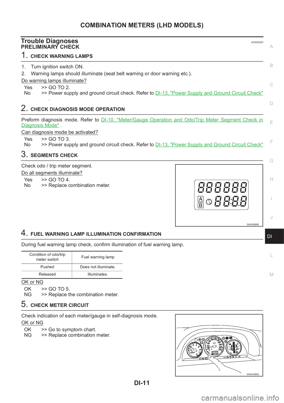
Check odo / trip meter segment.
Do all segments illuminate?
Ye s > > G O T O 4 .
No >> Replace combination meter.
4.FUEL WARNING LAMP ILLUMINATION CONFIRMATION
During fuel warning lamp check, confirm illumination of fuel warning lamp.
OK or NG
OK >> GO TO 5.
NG >> Replace the combination meter.
5.CHECK METER CIRCUIT
Check indication of each meter/gauge in self-diagnosis mode.
OK or NG
OK >> Go to symptom chart.
NG >> Replace combination meter.
SKIA0899E
Condition of odo/trip
meter switchFuel warning lamp
Pushed Does not illuminate.
Released Illuminates.
SKIA4366E
Page 3588 of 3833
DI-30
COMBINATION METERS (RHD MODELS)
Meter/Gauge Operation and Odo/Trip Meter Segment Check in Diagnosis Mode
EKS0030M
DIAGNOSIS FUNCTION
●Odo/trip meter segment can be checked in diagnosis mode.
●Meters/gauges can be checked in diagnosis mode.
HOW TO ALTERNATE DIAGNOSIS MODE
1. Turn ignition switch to ON and change odo/trip meter to “TRIP A” or “TRIP B”.
2. Turn ignition switch to OFF.
3. Turn ignition switch to ON when pushing odo/trip meter switch.
4. Confirm that trip meter indicates “000.0”.
5. Push odo/trip meter switch more than three times within 5 seconds.
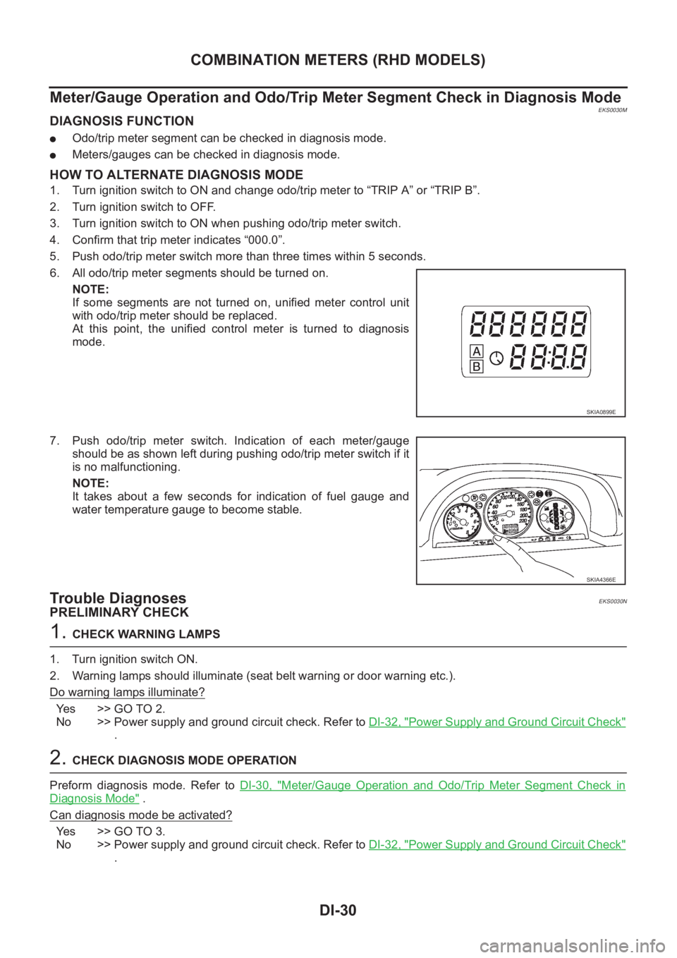
6. All odo/trip meter segments should be turned on.
NOTE:
If some segments are not turned on, unified meter control unit
with odo/trip meter should be replaced.
At this point, the unified control meter is turned to diagnosis
mode.
7. Push odo/trip meter switch. Indication of each meter/gauge
should be as shown left during pushing odo/trip meter switch if it
is no malfunctioning.
NOTE:
It takes about a few seconds for indication of fuel gauge and
water temperature gauge to become stable.
Trouble DiagnosesEKS0030N
PRELIMINARY CHECK
1. CHECK WARNING LAMPS
1. Turn ignition switch ON.
2. Warning lamps should illuminate (seat belt warning or door warning etc.).
Do warning lamps illuminate?
Yes >> GO TO 2.
No >> Power supply and ground circuit check. Refer to DI-32, "
Power Supply and Ground Circuit Check"
.
2. CHECK DIAGNOSIS MODE OPERATION
Preform diagnosis mode. Refer to DI-30, "
Meter/Gauge Operation and Odo/Trip Meter Segment Check in
Diagnosis Mode" .
Can diagnosis mode be activated?
Yes >> GO TO 3.
No >> Power supply and ground circuit check. Refer to DI-32, "
Power Supply and Ground Circuit Check"
.
SKIA0899E
SKIA4366E
Page 3616 of 3833
DI-58
WARNING CHIME
WARNING CHIME
PFP:24814
System DescriptionEKS002XF
POWER SUPPLY AND GROUND CIRCUIT
Power is supplied at all times
●to combination switch terminal 11 and
●to daytime light control unit terminal 1 (with daytime light system)
●through 10A fuse (No.31, located in fuse and fusible link box), and
●to key switch terminal 1 and
●to time control unit terminal 1
●through 10A fuse [No.28, located in the fuse block (J/B)].
With ignition switch in ON or START position, power is supplied
●to time control unit terminal 17
●through 10A fuse [No.5, located in the fuse block (J/B)].
Ground is supplied
●to time control unit terminal 16
●through body grounds M27 and M70.
IGNITION KEY WARNING CHIME
With ignition switch in OFF or ACC position, and the driver's door open and driver’s door locked, the warning
chime will sound. Power is supplied
●to time control unit terminal 18
●through key switch terminal 2 and
Ground is supplied
●to time control unit terminal 28
●through front door lock actuator (driver side) terminal 5
Front door lock actuator (driver side) terminal 2 is grounded through body grounds M27 and M70, and
Ground is supplied
●to time control unit terminal 30
●through front door switch (driver side) terminal 2.
Front door switch (driver side) terminal 3 is grounded through body grounds B8 and B18.
LIGHT WARNING CHIME
With ignition switch OFF position, driver's door open, and lighting switch in 1ST or 2ND position, warning
chime will sound. Power is supplied
●from the lighting switch terminal 12 or daytime light control unit terminal 11 (with daytime light system)
●to time control unit terminal 19.
Ground is supplied
●to time control unit terminal 30
●through front door switch (driver side) terminal 2.
Front door switch (driver side) terminal 3 is grounded through body grounds B8 and B18.
SEAT BELT WARNING CHIME
When the vehicle speed exceeds 25 km/h (16MPH) with driver side or passenger side seat belt unfastened
(seat belt switch ON), warning chime will sound. Refer to SB-6, "
SEAT BELT WARNING SYSTEM" .
Page 3619 of 3833
WARNING CHIME
DI-61
C
D
E
F
G
H
I
J
L
MA
B
DI
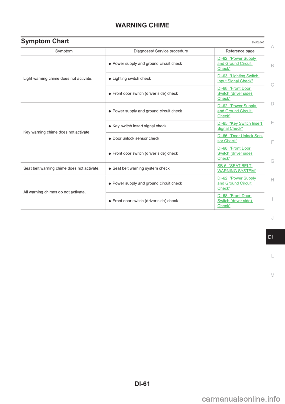
Symptom ChartEKS002XQ
Symptom Diagnoses/ Service procedure Reference page
Light warning chime does not activate.
●Power supply and ground circuit checkDI-62, "
Power Supply
and Ground Circuit
Check"
●Lighting switch checkDI-63, "Lighting Switch
Input Signal Check"
●Front door switch (driver side) checkDI-68, "
Front Door
Switch (driver side)
Check"
Key warning chime does not activate.
●Power supply and ground circuit checkDI-62, "
Power Supply
and Ground Circuit
Check"
●Key switch insert signal checkDI-65, "Key Switch Insert
Signal Check"
●Door unlock sensor checkDI-66, "Door Unlock Sen-
sor Check"
●Front door switch (driver side) checkDI-68, "
Front Door
Switch (driver side)
Check"
Seat belt warning chime does not activate.●Seat belt warning system checkSB-6, "SEAT BELT
WARNING SYSTEM"
All warning chimes do not activate.
●Power supply and ground circuit checkDI-62, "
Power Supply
and Ground Circuit
Check"
●Front door switch (driver side) checkDI-68, "
Front Door
Switch (driver side)
Check"
Page 3629 of 3833
WW-1
WIPER, WASHER & HORN
K ELECTRICAL
CONTENTS
C
D
E
F
G
H
I
J
L
M
SECTION
A
B
WW
WIPER, WASHER & HORN
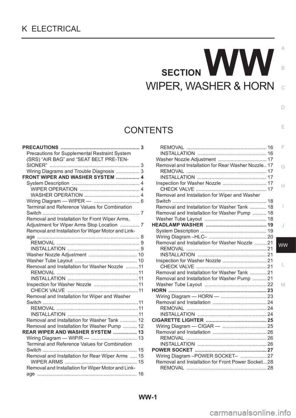
PRECAUTIONS .......................................................... 3
Precautions for Supplemental Restraint System
(SRS) “AIR BAG” and “SEAT BELT PRE-TEN-
SIONER” .................................................................. 3
Wiring Diagrams and Trouble Diagnosis .................. 3
FRONT WIPER AND WASHER SYSTEM .................. 4
System Description .................................................. 4
WIPER OPERATION ............................................ 4
WASHER OPERATION ......................................... 4
Wiring Diagram — WIPER — .................................. 6
Terminal and Reference Values for Combination
Switch ....................................................................... 7
Removal and Installation for Front Wiper Arms,
Adjustment for Wiper Arms Stop Location ............... 7
Removal and Installation for Wiper Motor and Link-
age ........................................................................... 8
REMOVAL ............................................................. 9
INSTALLATION ..................................................... 9
Washer Nozzle Adjustment .................................... 10
Washer Tube Layout .............................................. 10
Removal and Installation for Washer Nozzle .......... 11
REMOVAL ............................................................ 11
INSTALLATION .................................................... 11
Inspection for Washer Nozzle ................................. 11
CHECK VALVE .................................................... 11
Removal and Installation for Wiper and Washer
Switch ...................................................................... 11
REMOVAL ............................................................ 11
INSTALLATION .................................................... 11
Removal and Installation for Washer Tank ............. 12
Removal and Installation for Washer Pump ........... 12
REAR WIPER AND WASHER SYSTEM .................. 13
Wiring Diagram — WIP/R — .................................. 13
Terminal and Reference Values for Combination
Switch ..................................................................... 15
Removal and Installation for Rear Wiper Arms ...... 15
WIPER ARMS ..................................................... 15
Removal and Installation for Wiper Motor and Link-
age ......................................................................... 16REMOVAL ........................................................... 16
INSTALLATION ................................................... 16
Washer Nozzle Adjustment .................................... 17
Removal and Installation for Rear Washer Nozzle ... 17
REMOVAL ........................................................... 17
INSTALLATION ................................................... 17
Inspection for Washer Nozzle ................................. 17
CHECK VALVE .................................................... 17
Removal and Installation for Wiper and Washer
Switch ..................................................................... 18
Removal and Installation for Washer Tank ............. 18
Removal and Installation for Washer Pump ........... 18
Washer Tube Layout .............................................. 18
HEADLAMP WASHER ............................................. 19
System Description ................................................. 19
Wiring Diagram –HLC– ........................................... 20
Removal and Installation for Washer Nozzle .......... 21
REMOVAL ........................................................... 21
INSTALLATION ................................................... 21
Inspection for Washer Nozzle ................................. 21
CHECK VALVE .................................................... 21
Removal and Installation for Washer Tank ............. 21
Removal and Installation for Washer Pump ........... 21
Washer Tube Layout .............................................. 22
HORN ........................................................................ 23
Wiring Diagram — HORN — .................................. 23
Removal and Installation ........................................ 24
REMOVAL ........................................................... 24
INSTALLATION ................................................... 24
CIGARETTE LIGHTER ............................................. 25
Wiring Diagram — CIGAR — ................................. 25
Removal and Installation ........................................ 26
REMOVAL ........................................................... 26
INSTALLATION ................................................... 26
POWER SOCKET ..................................................... 27
Wiring Diagram –POWER SOCKET– .................... 27
Removal and Installation for Front Power Socket ... 28
REMOVAL ........................................................... 28
Page 3631 of 3833
PRECAUTIONS
WW-3
C
D
E
F
G
H
I
J
L
MA
B
WW
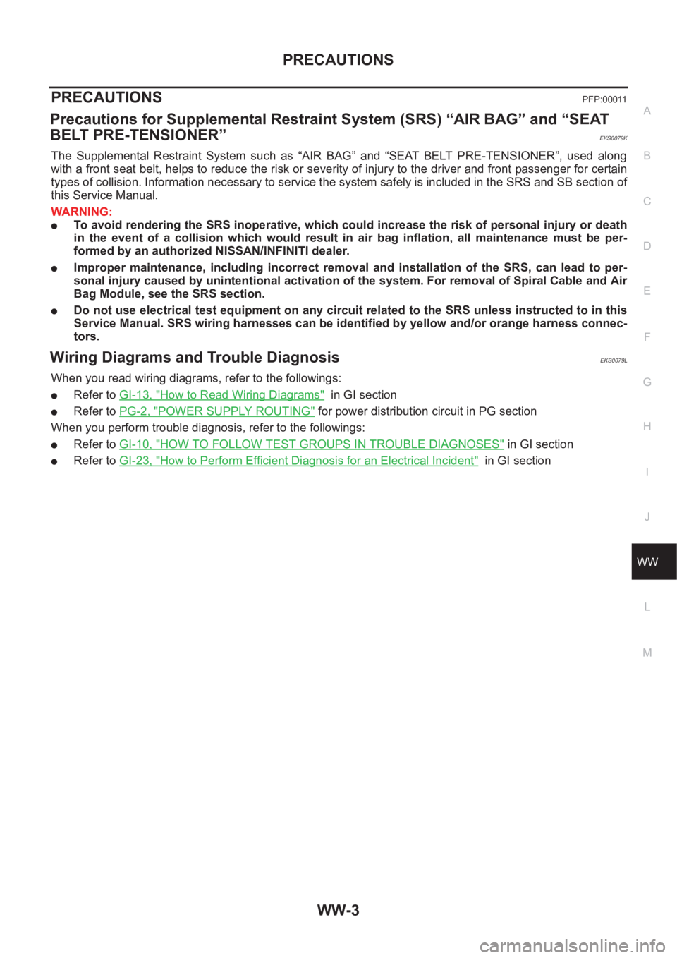
PRECAUTIONS PFP:00011
Precautions for Supplemental Restraint System (SRS) “AIR BAG” and “SEAT
BELT PRE-TENSIONER”
EKS0079K
The Supplemental Restraint System such as “AIR BAG” and “SEAT BELT PRE-TENSIONER”, used along
with a front seat belt, helps to reduce the risk or severity of injury to the driver and front passenger for certain
types of collision. Information necessary to service the system safely is included in the SRS and SB section of
this Service Manual.
WARNING:
●To avoid rendering the SRS inoperative, which could increase the risk of personal injury or death
in the event of a collision which would result in air bag inflation, all maintenance must be per-
formed by an authorized NISSAN/INFINITI dealer.
●Improper maintenance, including incorrect removal and installation of the SRS, can lead to per-
sonal injury caused by unintentional activation of the system. For removal of Spiral Cable and Air
Bag Module, see the SRS section.
●Do not use electrical test equipment on any circuit related to the SRS unless instructed to in this
Service Manual. SRS wiring harnesses can be identified by yellow and/or orange harness connec-
tors.
Wiring Diagrams and Trouble Diagnosis EKS0079L
When you read wiring diagrams, refer to the followings:
●Refer to GI-13, "How to Read Wiring Diagrams" in GI section
●Refer to PG-2, "POWER SUPPLY ROUTING" for power distribution circuit in PG section
When you perform trouble diagnosis, refer to the followings:
●Refer to GI-10, "HOW TO FOLLOW TEST GROUPS IN TROUBLE DIAGNOSES" in GI section
●Refer to GI-23, "How to Perform Efficient Diagnosis for an Electrical Incident" in GI section
Page 3657 of 3833
BCS-1
BODY CONTROL SYSTEM
K ELECTRICAL
CONTENTS
C
D
E
F
G
H
I
J
L
M
SECTION
A
B
BCS
BODY CONTROL SYSTEM
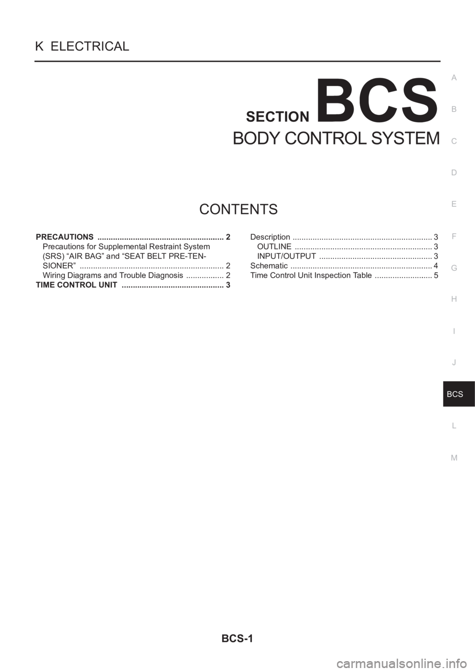
PRECAUTIONS .......................................................... 2
Precautions for Supplemental Restraint System
(SRS) “AIR BAG” and “SEAT BELT PRE-TEN-
SIONER” .................................................................. 2
Wiring Diagrams and Trouble Diagnosis .................. 2
TIME CONTROL UNIT ............................................... 3Description ................................................................ 3
OUTLINE ............................................................... 3
INPUT/OUTPUT .................................................... 3
Schematic ................................................................. 4
Time Control Unit Inspection Table ........................... 5