2001 NISSAN X-TRAIL height
[x] Cancel search: heightPage 46 of 3833

GI-44
IDENTIFICATION INFORMATION
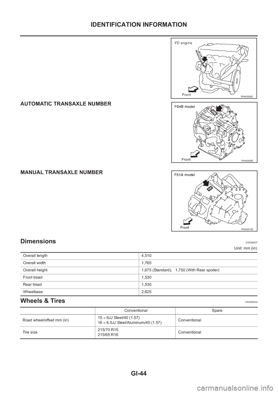
AUTOMATIC TRANSAXLE NUMBER
MANUAL TRANSAXLE NUMBER
Dimensions EAS000GF
Unit: mm (in)
Wheels & Tires EAS000GG
PAIA0008E
PAIA0009E
PAIA0010E
Overall length 4,510
Overall width 1,765
Overall height 1,675 (Standard), 1,750 (With Rear spoiler)
Front tread 1,530
Rear tread 1,530
Wheelbase 2,625
Conventional Spare
Road wheel/offset mm (in)15 × 6JJ Steel/40 (1.57)
16 × 6.5JJ Steel/Aluminum/40 (1.57)Conventional
Tir e s iz e215/70 R15
215/65 R16Conventional
Page 52 of 3833

EM-2
TIMING CHAIN .......................................................... 37
Removal and Installation ........................................ 37
REMOVAL ........................................................... 38
INSPECTION AFTER REMOVAL ........................ 41
INSTALLATION .................................................... 41
CAMSHAFT ............................................................... 46
Removal and Installation ........................................ 46
REMOVAL ........................................................... 46
INSTALLATION .................................................... 48
INSPECTION AFTER REMOVAL ........................ 51
Valve Clearance ...................................................... 53
INSPECTION ....................................................... 53
ADJUSTMENT .................................................... 54
OIL SEAL .................................................................. 56
Removal and Installation of Valve Oil Seal ............. 56
REMOVAL ........................................................... 56
INSTALLATION .................................................... 56
Removal and Installation of Front Oil Seal ............. 56
REMOVAL ........................................................... 56
INSTALLATION .................................................... 57
Removal and Installation of Rear Oil Seal .............. 57
REMOVAL ........................................................... 57
INSTALLATION .................................................... 57
CYLINDER HEAD .................................................. ... 59
On-Vehicle Service ................................................. 59
CHECKING COMPRESSION PRESSURE ......... 59
Removal and Installation ........................................ 60
REMOVAL ........................................................... 60
INSPECTION AFTER REMOVAL ........................ 61
INSTALLATION .................................................... 61
Disassembly and Assembly .................................... 62
DISASSEMBLY ................................................... 63
ASSEMBLY ......................................................... 63
Inspection After Disassembly ................................. 64
CYLINDER HEAD DISTORTION ........................ 64
VALVE DIMENSIONS .......................................... 64
VALVE GUIDE CLEARANCE .............................. 65
VALVE GUIDE REPLACEMENT ......................... 65
VALVE SEAT CONTACT ..................................... 66
VALVE SEAT REPLACEMENT ........................... 66
VALVE SPRING SQUARENESS ......................... 67
VALVE SPRING DIMENSIONS AND VALVE
SPRING PRESSURE LOAD ............................... 68
ENGINE ASSEMBLY ................................................ 69
Removal and Installation ........................................ 69
REMOVAL .......................................................
.... 69
INSTALLATION .................................................... 71
INSPECTION AFTER INSTALLATION ................ 71
CYLINDER BLOCK ................................................... 73
Disassembly and Assembly .................................... 73
DISASSEMBLY ................................................... 74
ASSEMBLY ......................................................... 78
How to Select Piston and Bearing .......................... 82
DESCRIPTION .................................................... 82
HOW TO SELECT PISTON ................................. 83
HOW TO SELECT CONNECTING ROD BEAR-
ING ...................................................................... 83HOW TO SELECT MAIN BEARING .................... 85
Inspection After Disassembly .................................. 88
CRANKSHAFT END PLAY .................................. 88
CONNECTING ROD SIDE CLEARANCE ........... 89
PISTON AND PISTON PIN CLEARANCE ........... 89
PISTON RING SIDE CLEARANCE ..................... 90
PISTON RING END GAP .................................... 90
CONNECTING ROD BEND AND TORSION ....... 91
CONNECTING ROD BEARING (BIG END) ........ 91
CONNECTING ROD BUSHING OIL CLEAR-
ANCE (SMALL END) ........................................... 91
CYLINDER BLOCK DISTORTION ...................... 92
INNER DIAMETER OF MAIN BEARING HOUS-
ING ....................................................................... 93
PISTON TO CYLINDER BORE CLEARANCE .... 93
OUTER DIAMETER OF CRANKSHAFT JOUR-
NAL ...................................................................... 94
OUTER DIAMETER OF CRANKSHAFT PIN ...... 94
OUT-OF-ROUND AND TAPER OF CRANK-
SHAFT ................................................................. 94
CRANKSHAFT RUNOUT .................................... 95
CONNECTING ROD BEARING OIL CLEAR-
ANCE ................................................................... 95
MAIN BEARING OIL CLEARANCE ..................... 95
MAIN BEARING CRUSH HEIGHT ...................... 96
OUTER DIAMETER OF LOWER CYLINDER
BLOCK MOUNTING BOLT .................................. 96
OUTER DIAMETER OF CONNECTING ROD
BOLT .................................................................... 96
MOVEMENT AMOUNT OF FLYWHEEL (M/T
MODELS) ............................................................. 97
SERVICE DATA AND SPECIFICATIONS (SDS) ...... 98
Standard and Limit .................................................. 98
GENERAL SPECIFICATIONS ............................. 98
DRIVE BELTS ...................................................... 98
INTAKE MANIFOLD AND EXHAUST MANI-
FOLD ................................................................... 98
SPARK PLUG ...................................................... 98
CYLINDER HEAD ................................................ 98
VALVE .................................................................. 99
CAMSHAFT AND CAMSHAFT BEARING .........102
CYLINDER BLOCK ............................................102
PISTON, PISTON RING AND PISTON PIN .....
.103
CONNECTING ROD ..........................................104
CRANKSHAFT ...................................................105
MAIN BEARING .................................................106
CONNECTING ROD BEARING .........................107
Tightening Torque .................................................108
YD22DDTi
PRECAUTIONS .......................................................110
Precautions for Drain Engine Coolant ...................110
Precautions for Disconnecting Fuel Piping ...........110
Precautions for Removal and Disassembly ..........110
Precautions for Inspection, Repair and Replace-
ment ......................................................................110
Precautions for Assembly and Installation ............110
Page 54 of 3833

EM-4
INSPECTION AFTER REMOVAL ......................184
INSTALLATION ..................................................185
Disassembly and Assembly ..................................187
DISASSEMBLY .................................................187
ASSEMBLY .......................................................188
INSPECTION AFTER DISASSEMBLY ..............188
ENGINE ASSEMBLY ..............................................193
Removal and Installation ......................................193
REMOVAL .........................................................194
INSTALLATION ..................................................195
INSPECTION AFTER INSTALLATION ..............196
CYLINDER BLOCK .................................................197
Disassembly and Assembly ..................................197
DISASSEMBLY .................................................198
ASSEMBLY .......................................................202
How to Select Piston and Bearing ........................206
DESCRIPTION ..................................................206
HOW TO SELECT PISTON ...............................206
HOW TO SELECT CONNECTING ROD BEAR-
ING ....................................................................207
HOW TO SELECT MAIN BEARING ..................208
Inspection After Disassembly ...............................210
CRANKSHAFT END PLAY ................................210
CONNECTING ROD SIDE CLEARANCE .........210
PISTON TO PISTON PIN CLEARANCE ...........210
PISTON RING SIDE CLEARANCE ...................211
PISTON RING END GAP ..................................211
CONNECTING ROD BEND AND TORSION .....212
CONNECTING ROD BIG END INNER DIAME-
TER ...................................................................212
CONNECTING ROD BUSHING OIL CLEAR-
ANCE (SMALL END) .........................................212
CYLINDER BLOCK TOP SURFACE DISTOR-TION ..................................................................213
MAIN BEARING HOUSING INNER DIAMETER .213
PISTON TO CYLINDER BORE CLEARANCE ..214
CRANKSHAFT JOURNAL OUTER DIAMETER .215
CRANKSHAFT PIN OUTER DIAMETER ..........215
CRANKSHAFT OUT-OF-ROUND AND TAPER .215
CRANKSHAFT RUNOUT ..................................216
CONNECTING ROD BEARING OIL CLEAR-
ANCE .................................................................216
MAIN BEARING OIL CLEARANCE ...................216
MAIN BEARING CRUSH HEIGHT ....................217
MAIN BEARING CAP BOLT DEFORMATION ...217
CONNECTING ROD BOLT DEFORMATION ....217
OIL JET ..............................................................218
OIL JET RELIEF VALVE ....................................218
MOVEMENT AMOUNT OF FLYWHEEL ...........218
SERVICE DATA AND SPECIFICATIONS (SDS) ....220
Standard and Limit ...............................................
.220
GENERAL SPECIFICATIONS ...........................220
INTAKE MANIFOLD AND EXHAUST MANI-
FOLD .................................................................220
DRIVE BELTS ....................................................220
CYLINDER HEAD ..............................................221
VALVE ................................................................221
CAMSHAFT AND CAMSHAFT BEARING .........225
CYLINDER BLOCK ............................................225
PISTON, PISTON RING AND PISTON PIN ......226
CONNECTING ROD ..........................................227
CRANKSHAFT ...................................................227
AVAILABLE MAIN BEARING .............................228
AVAILABLE CONNECTING ROD BEARING .....228
MISCELLANEOUS COMPONENTS ..................228
Tightening Torque .................................................229
Page 74 of 3833
![NISSAN X-TRAIL 2001 Service Repair Manual EM-24
[QR]
EXHAUST MANIFOLD AND THREE WAY CATALYST
EXHAUST MANIFOLD AND THREE WAY CATALYST
PFP:14004
Removal and InstallationEBS00KND
REMOVAL
1. Remove heated oxygen sensors.
●Follow below steps to NISSAN X-TRAIL 2001 Service Repair Manual EM-24
[QR]
EXHAUST MANIFOLD AND THREE WAY CATALYST
EXHAUST MANIFOLD AND THREE WAY CATALYST
PFP:14004
Removal and InstallationEBS00KND
REMOVAL
1. Remove heated oxygen sensors.
●Follow below steps to](/manual-img/5/57405/w960_57405-73.png)
EM-24
[QR]
EXHAUST MANIFOLD AND THREE WAY CATALYST
EXHAUST MANIFOLD AND THREE WAY CATALYST
PFP:14004
Removal and InstallationEBS00KND
REMOVAL
1. Remove heated oxygen sensors.
●Follow below steps to remove each heated oxygen sensor.
a. Remove engine undercover.
b. Disconnect harness connector of each heated oxygen sensor, and harness from bracket and middle
clamp.
c. Using heated oxygen sensor wrench, remove heated oxygen
sensors.
CAUTION:
●Be careful not to damage heated oxygen sensor.
●Discard any heated oxygen sensor which has been
dropped from a height of more than 0.5 m (19.7 in) onto a
hard surface such as a concrete floor; use a new one.
2. Remove exhaust manifold and three way catalyst assembly.
a. Remove exhaust manifold cover lower.
b. Remove exhaust front tube. Refer to EX-2, "
Removal and Instal-
lation" .
PBIC0279E
1.Exhaust manifold and three way cat-
alyst assembly2. Gasket 3. Exhaust manifold cover
4. Heated oxygen sensor 1 5. Heated oxygen sensor 2
KBIA0094E
Page 101 of 3833
![NISSAN X-TRAIL 2001 Service Repair Manual CAMSHAFT
EM-51
[QR]
C
D
E
F
G
H
I
J
K
L
MA
EM
INSPECTION AFTER REMOVAL
Camshaft Runout
●Put V-block on a precise flat table, and support No. 2 and 5 jour-
nal of camshaft.
●Set dial gauge vertical NISSAN X-TRAIL 2001 Service Repair Manual CAMSHAFT
EM-51
[QR]
C
D
E
F
G
H
I
J
K
L
MA
EM
INSPECTION AFTER REMOVAL
Camshaft Runout
●Put V-block on a precise flat table, and support No. 2 and 5 jour-
nal of camshaft.
●Set dial gauge vertical](/manual-img/5/57405/w960_57405-100.png)
CAMSHAFT
EM-51
[QR]
C
D
E
F
G
H
I
J
K
L
MA
EM
INSPECTION AFTER REMOVAL
Camshaft Runout
●Put V-block on a precise flat table, and support No. 2 and 5 jour-
nal of camshaft.
●Set dial gauge vertically to No. 3 journal.
●Turn camshaft to one direction with hands, and measure cam-
shaft runout on dial gauge. (Total indicator reading)
Camshaft Cam Height
1. Measure camshaft cam height.
2. If wear is beyond the limit, replace camshaft.
Camshaft Journal Clearance
Outer Diameter of Camshaft Journal
Measure outer diameter of camshaft journal.
Inner Diameter of Camshaft Bracket
●Tighten camshaft bracket bolt with specified torque.
●Using inside micrometer, measure inner diameter of camshaft
bracket.
Calculation of Camshaft Journal Clearance
(Journal clearance) = (inner diameter of camshaft bracket) – (outer
diameter of camshaft journal).
●When out of the specified range above, replace either or both camshaft and cylinder head.
NOTICE:
Inner diameter of camshaft bracket is manufactured together with cylinder head. Replace the whole cylin-
der head assembly.Standard: Less than 0.02 mm (0.0008 in).
PBIC0038E
Standard cam height:
Intake : 45.665 - 45.855 mm (1.7978 - 1.8053 in)
Exhaust
QR20DE : 42.825 - 43.015 mm (1.6860 - 1.6935 in)
QR25DE : 43.975 - 44.165 mm (1.7313 - 1.7388 in)
PBIC0039E
Standard outer diameter:
No. 1 : 27.935 - 27.955 mm (1.0998 - 1.1006 in)
No. 2, 3, 4, 5 : 23.435 - 23.455 mm (0.9226 - 0.9234 in)
PBIC0040E
Standard:
No. 1 : 28.000 - 28.021 mm (1.1024 - 1.1032 in)
No. 2, 3, 4, 5 : 23.500 - 23.521 mm (0.9252 - 0.9260 in)
Standard: 0.045 - 0.086 mm (0.0018 - 0.0034 in)
PBIC0041E
Page 114 of 3833
![NISSAN X-TRAIL 2001 Service Repair Manual EM-64
[QR]
CYLINDER HEAD
5. Install valve spring.
●Install smaller pitch (valve spring seat side) to cylinder head
side.
●Confirm identification color of valve spring.
6. Install valve sp NISSAN X-TRAIL 2001 Service Repair Manual EM-64
[QR]
CYLINDER HEAD
5. Install valve spring.
●Install smaller pitch (valve spring seat side) to cylinder head
side.
●Confirm identification color of valve spring.
6. Install valve sp](/manual-img/5/57405/w960_57405-113.png)
EM-64
[QR]
CYLINDER HEAD
5. Install valve spring.
●Install smaller pitch (valve spring seat side) to cylinder head
side.
●Confirm identification color of valve spring.
6. Install valve spring retainer.
7. Install valve collet.
●Compress valve spring with valve spring compressor. Install
valve collet with magnet hand.
●Tap stem edge lightly with plastic hammer after installation to check its installed condition.
8. Install valve lifter.
9. Install spark plug tube.
●Press fit it into cylinder head as follows.
a. Remove old liquid gasket from cylinder head side mounting
hole.
b. Apply liquid gasket all round on spark plug tube with a 12 mm
(0.47 in) width from edge of spark plug tube on the press fit side.
Use Genuine Liquid gasket or equivalent.
c. Using a drift (commercial service tool), press fit spark plug tube
so that height is as same as H shown in figure.
CAUTION:
●When press fitting be careful not to deform spark plug tube.
●After press fitting, wipe off any protruding liquid gasket on top surface of cylinder head.
10. Install spark plug with spark plug wrench.
Inspection After DisassemblyEBS00KNS
CYLINDER HEAD DISTORTION
1. Wipe off engine oil and remove water scale (like deposit), gas-
ket, sealer, carbon, etc with scraper.
CAUTION:
Use utmost care not to allow gasket debris to enter pas-
sages for engine oil or water.
2. At each of several locations on bottom surface of cylinder head,
measure distortion in six directions.
VALVE DIMENSIONS
Check dimensions of each valve. For dimensions, refer to SDS, EM-
99, "Valve Dimensions" . Intake : Blue
Exhaust : Yellow
Press fit height “H” standard value:
38.55 - 38.65 mm (1.518 - 1.522 in)
PBIC0525E
SBIA0252E
Standard: 0.1mm (0.004 in)
PBIC0075E
SEM188A
Page 118 of 3833
![NISSAN X-TRAIL 2001 Service Repair Manual EM-68
[QR]
CYLINDER HEAD
VALVE SPRING DIMENSIONS AND VALVE SPRING PRESSURE LOAD
Check valve spring pressure with valve spring seat installed at spec-
ified spring height.
CAUTION:
Do not remove valve NISSAN X-TRAIL 2001 Service Repair Manual EM-68
[QR]
CYLINDER HEAD
VALVE SPRING DIMENSIONS AND VALVE SPRING PRESSURE LOAD
Check valve spring pressure with valve spring seat installed at spec-
ified spring height.
CAUTION:
Do not remove valve](/manual-img/5/57405/w960_57405-117.png)
EM-68
[QR]
CYLINDER HEAD
VALVE SPRING DIMENSIONS AND VALVE SPRING PRESSURE LOAD
Check valve spring pressure with valve spring seat installed at spec-
ified spring height.
CAUTION:
Do not remove valve spring seat.
SEM113
Standard: INTAKE EXHAUST
Free height : 44.84 - 45.34 mm (1.7654 -
1.7850 in): 45.28 - 45.78 mm (1.7827 -
1.8024 in)
Installation height : 35.30 mm (1.390 in) : 35.30 mm (1.390 in)
Installation load : 151 - 175 N (15.4 - 17.8 kg, 34 -
39 lb): 151 - 175 N (15.4 - 17.8 kg, 34 -
39 lb)
Height during valve open : 24.94 mm (0.9819 in) : 26.39 mm (1.0390 in)
Load with valve open : 358 - 408 N (36.5 - 41.6 kg, 80 -
92 lb): 325 - 371 N (33.1 - 37.8 kg, 73 -
83 lb)
Identification color : Blue : Yellow
Page 146 of 3833
![NISSAN X-TRAIL 2001 Service Repair Manual EM-96
[QR]
CYLINDER BLOCK
Method of Using Plastigage
●Remove engine oil and dust on the crankshaft journal and the
surfaces of each bearing completely.
●Cut a plastigage slightly sh NISSAN X-TRAIL 2001 Service Repair Manual EM-96
[QR]
CYLINDER BLOCK
Method of Using Plastigage
●Remove engine oil and dust on the crankshaft journal and the
surfaces of each bearing completely.
●Cut a plastigage slightly sh](/manual-img/5/57405/w960_57405-145.png)
EM-96
[QR]
CYLINDER BLOCK
Method of Using Plastigage
●Remove engine oil and dust on the crankshaft journal and the
surfaces of each bearing completely.
●Cut a plastigage slightly shorter than the bearing width, and
place it in crankshaft axial direction, avoiding oil holes.
●Tighten the main bearing bolts to the specified torque.
CAUTION:
Never rotate the crankshaft.
●Remove the bearing cap and bearings, and using the scale on
the plastigage bag, measure the plastigage width.
NOTE:
The procedure when the measured value exceeds the limit is
same as that described in “Method of Measurement”.
MAIN BEARING CRUSH HEIGHT
●When the bearing cap is removed after being tightened to the
specified torque with main bearings installed, the tip end of bear-
ing must protrude.
●If the standard is not met, replace main bearings.
OUTER DIAMETER OF LOWER CYLINDER BLOCK MOUNTING BOLT
●Perform only with M10 (0.39 in) bolts.
●Measure outer diameters (d1, d2) at two positions shown in the figure.
●Measure d2 at a point within block A.
●When the value of d1- d2 exceeds the limit (a large difference in
dimensions), replace the bolt with a new one.
OUTER DIAMETER OF CONNECTING ROD BOLT
●Measure outer diameter (d) at position shown in the figure.
●When “d ” exceeds the limit (when it becomes thinner), replace
the bolt with a new one.
EM142
Standard: There must be crush height.
SEM502G
Limit: 0.13 mm (0.0051 in) or more.
SBIA0285E
Limit: 7.75 mm (0.3051 in) or less.
SBIA0286E