2001 NISSAN X-TRAIL center console
[x] Cancel search: center consolePage 2777 of 3833
PARKING BRAKE CONTROL
PB-3
C
D
E
G
H
I
J
K
L
MA
B
PB
PARKING BRAKE CONTROLPFP:36010
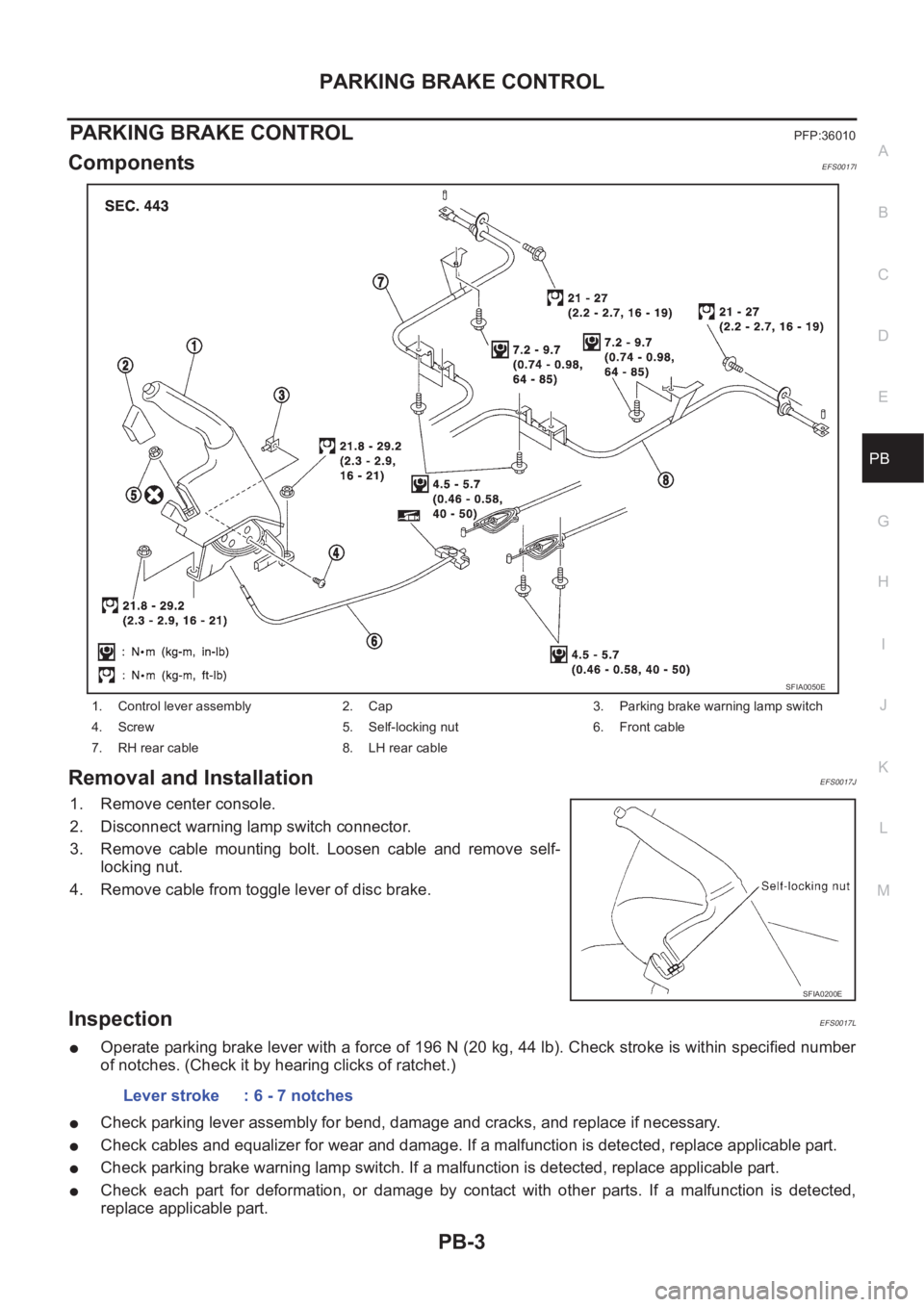
Components EFS0017I
Removal and InstallationEFS0017J
1. Remove center console.
2. Disconnect warning lamp switch connector.
3. Remove cable mounting bolt. Loosen cable and remove self-
locking nut.
4. Remove cable from toggle lever of disc brake.
InspectionEFS0017L
●Operate parking brake lever with a force of 196 N (20 kg, 44 lb). Check stroke is within specified number
of notches. (Check it by hearing clicks of ratchet.)
●Check parking lever assembly for bend, damage and cracks, and replace if necessary.
●Check cables and equalizer for wear and damage. If a malfunction is detected, replace applicable part.
●Check parking brake warning lamp switch. If a malfunction is detected, replace applicable part.
●Check each part for deformation, or damage by contact with other parts. If a malfunction is detected,
replace applicable part.
1. Control lever assembly 2. Cap 3. Parking brake warning lamp switch
4. Screw 5. Self-locking nut 6. Front cable
7. RH rear cable 8. LH rear cable
SFIA0050E
SFIA0200E
Lever stroke : 6 - 7 notches
Page 2834 of 3833
![NISSAN X-TRAIL 2001 Service Repair Manual BRC-50
[4WD/ABS]
G-SENSOR (4WD MODEL ONLY)
G-SENSOR (4WD MODEL ONLY)
PFP:47930
Removal and InstallationEFS001C2
CAUTION:
Be careful not to drop or bump G -sensor because it is sensitive to impact.
1. NISSAN X-TRAIL 2001 Service Repair Manual BRC-50
[4WD/ABS]
G-SENSOR (4WD MODEL ONLY)
G-SENSOR (4WD MODEL ONLY)
PFP:47930
Removal and InstallationEFS001C2
CAUTION:
Be careful not to drop or bump G -sensor because it is sensitive to impact.
1.](/manual-img/5/57405/w960_57405-2833.png)
BRC-50
[4WD/ABS]
G-SENSOR (4WD MODEL ONLY)
G-SENSOR (4WD MODEL ONLY)
PFP:47930
Removal and InstallationEFS001C2
CAUTION:
Be careful not to drop or bump G -sensor because it is sensitive to impact.
1. Remove center console and instrument. Refer to applicable sec-
tion in IP-3, "
INSTRUMENT PANEL ASSEMBLY" .
2. Disconnect G -sensor connector.
3. Remove mounting nuts and remove G -sensor.
Install in the reverse order of removal observing the precautions
above.
SFIA0065E
Page 3042 of 3833
SRS-40
DIAGNOSIS SENSOR UNIT
DIAGNOSIS SENSOR UNIT
PFP:28556
Removal and InstallationEHS000DD
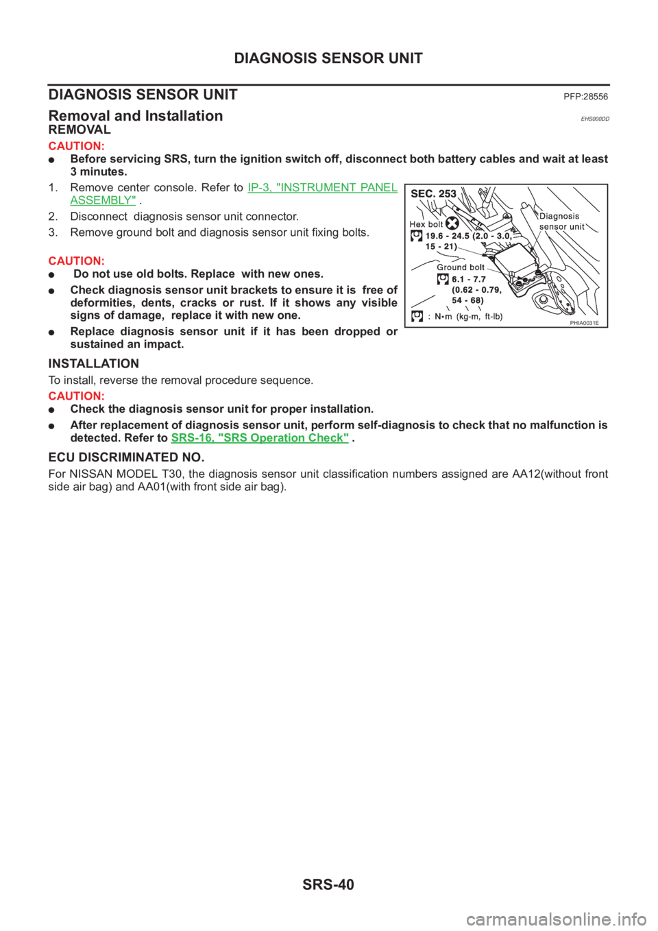
REMOVAL
CAUTION:
●Before servicing SRS, turn the ignition switch off, disconnect both battery cables and wait at least
3 minutes.
1. Remove center console. Refer to IP-3, "
INSTRUMENT PANEL
ASSEMBLY" .
2. Disconnect diagnosis sensor unit connector.
3. Remove ground bolt and diagnosis sensor unit fixing bolts.
CAUTION:
● Do not use old bolts. Replace with new ones.
●Check diagnosis sensor unit brackets to ensure it is free of
deformities, dents, cracks or rust. If it shows any visible
signs of damage, replace it with new one.
●Replace diagnosis sensor unit if it has been dropped or
sustained an impact.
INSTALLATION
To install, reverse the removal procedure sequence.
CAUTION:
●Check the diagnosis sensor unit for proper installation.
●After replacement of diagnosis sensor unit, perform self-diagnosis to check that no malfunction is
detected. Refer to SRS-16, "
SRS Operation Check" .
ECU DISCRIMINATED NO.
For NISSAN MODEL T30, the diagnosis sensor unit classification numbers assigned are AA12(without front
side air bag) and AA01(with front side air bag).
PHIA0031E
Page 3248 of 3833
EI-28
FLOOR TRIM
FLOOR TRIM
PFP:74902
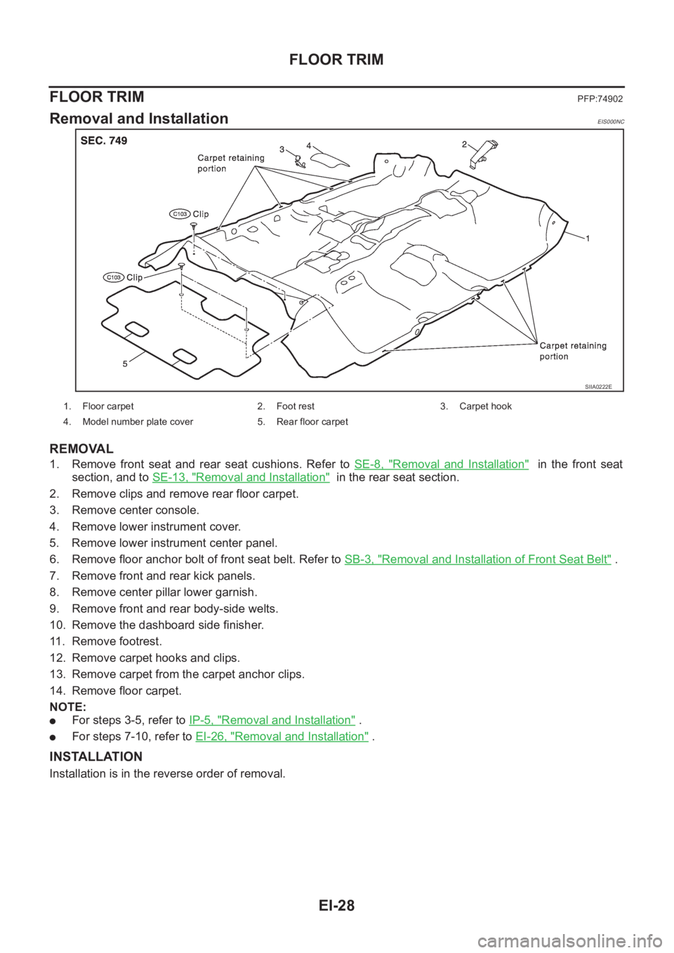
Removal and InstallationEIS000NC
REMOVAL
1. Remove front seat and rear seat cushions. Refer to SE-8, "Removal and Installation" in the front seat
section, and to SE-13, "
Removal and Installation" in the rear seat section.
2. Remove clips and remove rear floor carpet.
3. Remove center console.
4. Remove lower instrument cover.
5. Remove lower instrument center panel.
6. Remove floor anchor bolt of front seat belt. Refer to SB-3, "
Removal and Installation of Front Seat Belt" .
7. Remove front and rear kick panels.
8. Remove center pillar lower garnish.
9. Remove front and rear body-side welts.
10. Remove the dashboard side finisher.
11. Remove footrest.
12. Remove carpet hooks and clips.
13. Remove carpet from the carpet anchor clips.
14. Remove floor carpet.
NOTE:
●For steps 3-5, refer to IP-5, "Removal and Installation" .
●For steps 7-10, refer to EI-26, "Removal and Installation" .
INSTALLATION
Installation is in the reverse order of removal.
SIIA0222E
1. Floor carpet 2. Foot rest 3. Carpet hook
4. Model number plate cover 5. Rear floor carpet
Page 3251 of 3833
IP-1
INSTRUMENT PANEL
I BODY
CONTENTS
C
D
E
F
G
H
J
K
L
M
SECTION
A
B
IP
INSTRUMENT PANEL
PRECAUTIONS .......................................................... 2
Precautions for Supplemental Restraint System
(SRS) “AIR BAG” and “SEAT BELT PRE-TEN-
SIONER” .................................................................. 2
Precautions .............................................................. 2
INSTRUMENT PANEL ASSEMBLY ........................... 3
Component Parts Drawing ....................................... 3
Removal and Installation .......................................... 5
TABLE OF WORK ITEM ....................................... 5
FRONT SPEAKER GRILLE .................................. 6
INSTRUMENT FINISHER ..................................... 6
CUP HOLDER ....................................................... 6
CLUSTER LID A ................................................... 6
COMBINATION METER ....................................... 6
POCKET ............................................................... 6
STEERING COLUMN COVER ............................. 6
INSTRUMENT LOWER DRIVER PANEL ............. 7
MIRROR CONTROL SWITCH .............................. 7
GPS ANTENNA .................................................... 7
CLUSTER LID C ................................................... 7CLUSTER LID FINISHER ..................................... 7
AUDIO UNIT AND POCKET ................................. 7
HEATER CONTROL FINISHER ............................ 8
CD AUTO–CHANGER AND POCKET .................. 8
HEATER CONTROLLER ....................................... 8
A/T OR M/T FINISHER ......................................... 8
CONSOLE MASK AND CENTER CONSOLE ....... 8
LOWER INSTRUMENT COVER ........................... 8
INSTRUMENT LOWER CENTER PANEL ............ 8
GLOVE BOX ......................................................... 9
LOWER INSTRUMENT PANEL ............................ 9
GLOVE BOX COVER ............................................ 9
FRONT PASSENGER AIR BAG MODULE ........... 9
INSTRUMENT REINFORCEMENT ....................... 9
INSTRUMENT MASK ............................................ 9
FRONT PILLAR GARNISH ................................... 9
INSTRUMENT PANEL .......................................... 9
Disassembly and Assembly .................................... 10
CONSOLE BOX ASSEMBLY .............................. 10
Page 3254 of 3833

IP-4
INSTRUMENT PANEL ASSEMBLY
1. Front passenger air bag module 2. Front speaker grille (right) 3. Front side speaker (right)
4. Cup holder (right) 5. Instrument finisher B 6. Combination meter
7. Instrument mask (right) 8. GPS antenna 9. Instrument mask (left)
10. Instrument cluster lid A 11. Pocket 12. Front speaker grille (left)
13. Front side speaker (left) 14. Cup holder (left) 15. Mirror control switch
16. Instrument panel & pad 17. Instrument reinforcement 18. Audio unit and pocket
19. Glove box cover 20. Lower instrument panel 21. Glove box pin
22. Glove box 23. Cluster lid C 24. Instrument finisher A
25. Instrument lower driver panel 26. Column cover, key cylinder escutcheon 27. Cluster lid finisher (left)
28. Heater control finisher 29. CD auto–changer and pocket 30. instrument lower center panel
31. Lower instrument cover 32. Cluster lid finisher (right) 33. Center console
34. A/T or M/T finisher 35. Console mask 36. Seal case (inner case)
Page 3255 of 3833
![NISSAN X-TRAIL 2001 Service Repair Manual INSTRUMENT PANEL ASSEMBLY
IP-5
C
D
E
F
G
H
J
K
L
MA
B
IP
Removal and InstallationEIS000NI
TABLE OF WORK ITEM
[ ]: The number shows the removal order.
ComponentsInstrument
panelCombination
meterNavig NISSAN X-TRAIL 2001 Service Repair Manual INSTRUMENT PANEL ASSEMBLY
IP-5
C
D
E
F
G
H
J
K
L
MA
B
IP
Removal and InstallationEIS000NI
TABLE OF WORK ITEM
[ ]: The number shows the removal order.
ComponentsInstrument
panelCombination
meterNavig](/manual-img/5/57405/w960_57405-3254.png)
INSTRUMENT PANEL ASSEMBLY
IP-5
C
D
E
F
G
H
J
K
L
MA
B
IP
Removal and InstallationEIS000NI
TABLE OF WORK ITEM
[ ]: The number shows the removal order.
ComponentsInstrument
panelCombination
meterNavigation
DisplayAudio
Console
Up Down
Front speaker grille [1]
Instrument finisher A, B [2] [1]
Cup holder [3]
Instrument cluster lid A [4] [2]
Combination meter [5] [3]
Pocket [6]
Key cylinder escutcheon and steer-
ing column cover[7]
Instrument lower driver panel [8]
Mirror control switch [9]
GPS antenna [10]
Cluster lid C [11] [1] [1]
Cluster lid finisher [12] [1] [1]
Audio unit and pocket [13] [2] [2]
Heater control finisher [14] [2]
CD auto–changer and pocket [15] [3]
Heater controller [16]
A/T(M/T,CVT) finisher [17] [2]
Console mask [18] [3]
Center console [19] [4]
Lower instrument cover [20]
instrument lower center panel [21]
Glove box [22]
Lower instrument panel [23]
Glove box cover [24]
Front passenger air bag module [25]
Instrument reinforcement [26]
Instrument mask [27]
Front pillar garnish [28]
Instrument panel [29]
Page 3258 of 3833
IP-8
INSTRUMENT PANEL ASSEMBLY
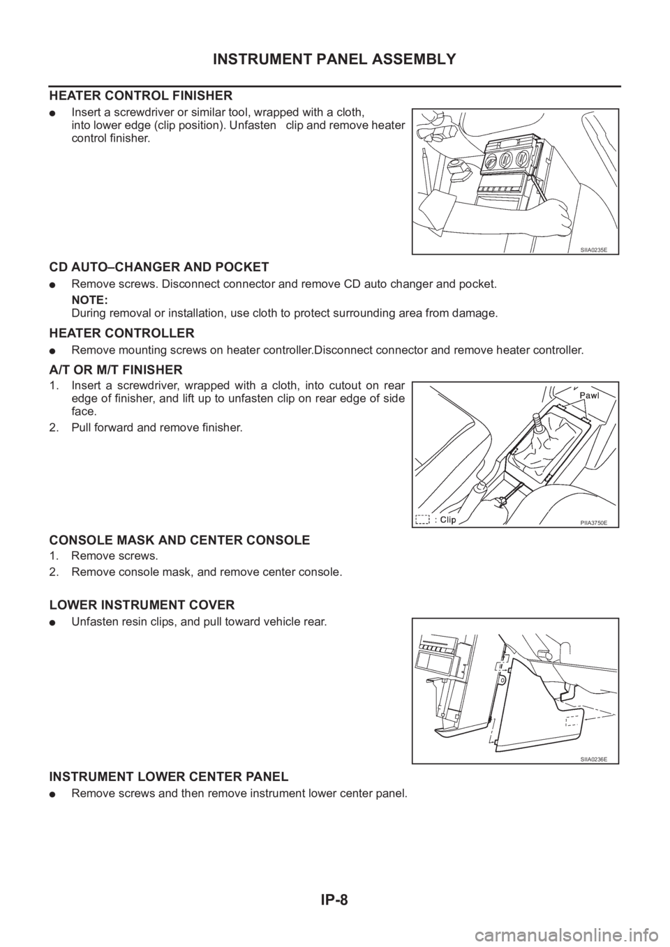
HEATER CONTROL FINISHER
●Insert a screwdriver or similar tool, wrapped with a cloth,
into lower edge (clip position). Unfasten clip and remove heater
control finisher.
CD AUTO–CHANGER AND POCKET
●Remove screws. Disconnect connector and remove CD auto changer and pocket.
NOTE:
During removal or installation, use cloth to protect surrounding area from damage.
HEATER CONTROLLER
●Remove mounting screws on heater controller.Disconnect connector and remove heater controller.
A/T OR M/T FINISHER
1. Insert a screwdriver, wrapped with a cloth, into cutout on rear
edge of finisher, and lift up to unfasten clip on rear edge of side
face.
2. Pull forward and remove finisher.
CONSOLE MASK AND CENTER CONSOLE
1. Remove screws.
2. Remove console mask, and remove center console.
LOWER INSTRUMENT COVER
●Unfasten resin clips, and pull toward vehicle rear.
INSTRUMENT LOWER CENTER PANEL
●Remove screws and then remove instrument lower center panel.
SIIA0235E
PIIA3750E
SIIA0236E