2001 NISSAN X-TRAIL battery location
[x] Cancel search: battery locationPage 12 of 3833

GI-10
HOW TO USE THIS MANUAL
1.Before performing trouble diagnoses, read the “Preliminary Check”, the “Symptom Chart” or the
“Work Flow”.
2.After repairs, re-check that the problem has been completely eliminated.
3.Refer to Component Parts and Harness Connector Location for the Systems described in each
section for identification/location of components and harness connectors.
4.Refer to the Circuit Diagram for quick pinpoint check.
If you need to check circuit continuity between harness connectors in more detail, such as when a
sub-harness is used, refer to Wiring Diagram in each individual section and Harness Layout in PG
section for identification of harness connectors.
5.When checking circuit continuity, ignition switch should be OFF.
6.Before checking voltage at connectors, check battery voltage.
7.After accomplishing the Diagnostic Procedures and Electrical Components Inspection, make sure
that all harness connectors are reconnected as they were.
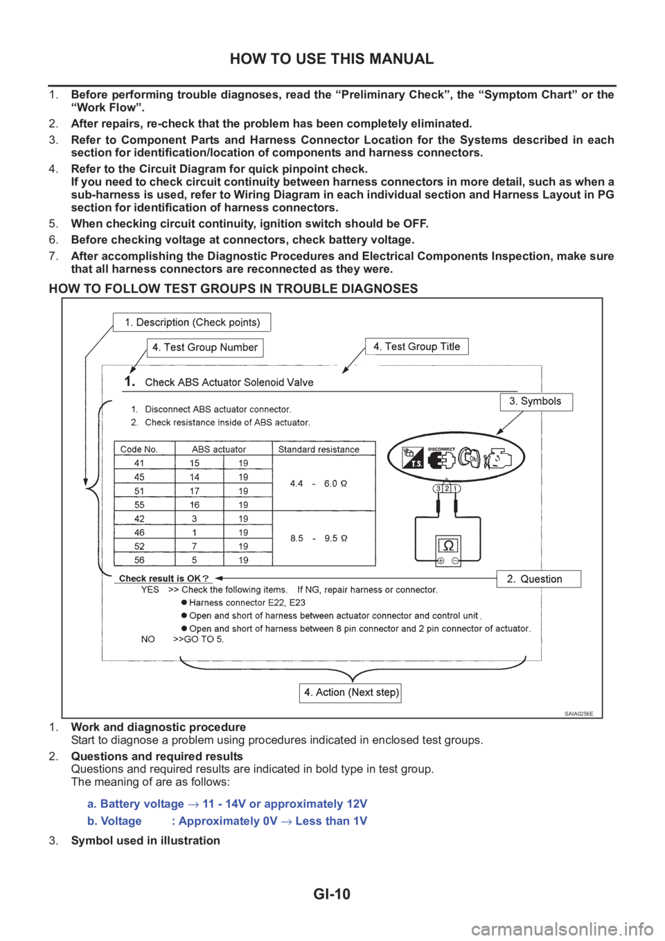
HOW TO FOLLOW TEST GROUPS IN TROUBLE DIAGNOSES
1.Work and diagnostic procedure
Start to diagnose a problem using procedures indicated in enclosed test groups.
2.Questions and required results
Questions and required results are indicated in bold type in test group.
The meaning of are as follows:
3.Symbol used in illustration
SAIA0256E
a. Battery voltage → 11 - 14V or approximately 12V
b. Voltage : Approximately 0V → Less than 1V
Page 18 of 3833

GI-16
HOW TO USE THIS MANUAL
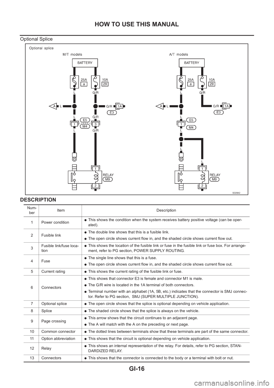
Optional Splice
DESCRIPTION
SGI942
Num-
berItem Description
1 Power condition
●This shows the condition when the system receives battery positive voltage (can be oper-
ated).
2 Fusible link
●The double line shows that this is a fusible link.
●The open circle shows current flow in, and the shaded circle shows current flow out.
3Fusible link/fuse loca-
tion
●This shows the location of the fusible link or fuse in the fusible link or fuse box. For arrange-
ment, refer to PG section, POWER SUPPLY ROUTING.
4Fuse
●The single line shows that this is a fuse.
●The open circle shows current flow in, and the shaded circle shows current flow out.
5 Current rating
●This shows the current rating of the fusible link or fuse.
6 Connectors
●This shows that connector E3 is female and connector M1 is male.
●The G/R wire is located in the 1A terminal of both connectors.
●Terminal number with an alphabet (1A, 5B, etc.) indicates that the connector is SMJ connec-
tor. Refer to PG section, SMJ (SUPER MULTIPLE JUNCTION).
7 Optional splice
●The open circle shows that the splice is optional depending on vehicle application.
8 Splice
●The shaded circle shows that the splice is always on the vehicle.
9 Page crossing
●This arrow shows that the circuit continues to an adjacent page.
●The A will match with the A on the preceding or next page.
10 Common connector
●The dotted lines between terminals show that these terminals are part of the same connector.
11 Option abbreviation
●This shows that the circuit is optional depending on vehicle application.
12 Relay
●This shows an internal representation of the relay. For details, refer to PG section, STAN-
DARDIZED RELAY.
13 Connectors
●This shows that the connector is connected to the body or a terminal with bolt or nut.
Page 476 of 3833
![NISSAN X-TRAIL 2001 Service Repair Manual EC-126
[QR25(WITH EURO-OBD)]
DTC P0011 IVT CONTROL
: Average voltage for pulse signal (Actual pulse signal can be confirmed by oscilloscope.)
On Board Diagnosis LogicEBS00M1N
FAIL-SAFE MODE
When the m NISSAN X-TRAIL 2001 Service Repair Manual EC-126
[QR25(WITH EURO-OBD)]
DTC P0011 IVT CONTROL
: Average voltage for pulse signal (Actual pulse signal can be confirmed by oscilloscope.)
On Board Diagnosis LogicEBS00M1N
FAIL-SAFE MODE
When the m](/manual-img/5/57405/w960_57405-475.png)
EC-126
[QR25(WITH EURO-OBD)]
DTC P0011 IVT CONTROL
: Average voltage for pulse signal (Actual pulse signal can be confirmed by oscilloscope.)
On Board Diagnosis LogicEBS00M1N
FAIL-SAFE MODE
When the malfunction is detected, the ECM enters fail-safe mode and the MI lights up.
DTC Confirmation ProcedureEBS00M1O
CAUTION:
Always drive at a safe speed.
NOTE:
●If DTC P0011 is displayed with DTC P1111, first perform trouble diagnosis for “DTC P1111”. See
EC-271
.
●If “DTC Confirmation Procedure” has been previously conducted, always turn ignition switch “OFF” and
wait at least 10 seconds before conducting the next test.
TESTING CONDITION:
Before performing the following procedure, confirm that battery voltage is between 10V and 16V at
idle.
WITH CONSULT-II
1. Turn ignition switch “ON”.
2. Select “DATA MONITOR” mode with CONSULT-II.
3. Maintain the following conditions for at least 20 consecutive sec-
onds.
TER-
MINAL
NO.WIRE
COLORITEM CONDITION DATA (DC Voltage)
107 Y/RIntake valve timing
control solenoid valve[Engine is running]
●Warm-up condition
●Idle speedBATTERY VOLTAGE
(11 - 14V)
[Engine is running]
●Warm-up condition
●When revving engine up to 2,000 rpm quicklyApproximately 4V - BATTERY
VOLTAGE (11 - 14V)
PBIB0532E
DTC No.Trouble diagnosis
nameDetecting condition Possible cause
P0011
0011Intake valve timing
control performanceThere is a gap between angle of target and
phase-control angle degree.
●Crankshaft position sensor (POS)
●Camshaft position sensor (PHASE)
●Accumulation of debris to the signal pick-up
portion of the camshaft
Detected items Engine operating condition in fail-safe mode
Intake valve timing control The signal is not energized to the solenoid valve and the valve control does not function
ENG SPEED 2,000 - 3,175 rpm (A constant rotation is maintained.)
COOLANT TEMPS 80 - 90°C (176 - 194°F)
Selector lever 1st or 2nd position
Driving location uphillDriving vehicle uphill
(Increased engine load will help maintain the driving
conditions required for this test.)
SEF174Y
Page 1208 of 3833
![NISSAN X-TRAIL 2001 Service Repair Manual EC-858
[QR20(WITH EURO-OBD)]
DTC P0011 IVT CONTROL
: Average voltage for pulse signal (Actual pulse signal can be confirmed by oscilloscope.)
On Board Diagnosis LogicEBS00MTM
FAIL-SAFE MODE
When the m NISSAN X-TRAIL 2001 Service Repair Manual EC-858
[QR20(WITH EURO-OBD)]
DTC P0011 IVT CONTROL
: Average voltage for pulse signal (Actual pulse signal can be confirmed by oscilloscope.)
On Board Diagnosis LogicEBS00MTM
FAIL-SAFE MODE
When the m](/manual-img/5/57405/w960_57405-1207.png)
EC-858
[QR20(WITH EURO-OBD)]
DTC P0011 IVT CONTROL
: Average voltage for pulse signal (Actual pulse signal can be confirmed by oscilloscope.)
On Board Diagnosis LogicEBS00MTM
FAIL-SAFE MODE
When the malfunction is detected, the ECM enters fail-safe mode and the MI lights up.
DTC Confirmation ProcedureEBS00MTN
CAUTION:
Always drive at a safe speed.
NOTE:
●If DTC P0011 is displayed with DTC P1111, first perform trouble diagnosis for “DTC P1111”. See
EC-1005
.
●If “DTC Confirmation Procedure” has been previously conducted, always turn ignition switch “OFF” and
wait at least 10 seconds before conducting the next test.
TESTING CONDITION:
Before performing the following procedure, confirm that battery voltage is between 10V and 16V at
idle.
WITH CONSULT-II
1. Turn ignition switch “ON”.
2. Select “DATA MONITOR” mode with CONSULT-II.
3. Maintain the following conditions for at least 20 consecutive sec-
onds.
TER-
MINAL
NO.WIRE
COLORITEM CONDITION DATA (DC Voltage)
107 Y/RIntake valve timing
control solenoid valve[Engine is running]
●Warm-up condition
●Idle speedBATTERY VOLTAGE
(11 - 14V)
[Engine is running]
●Warm-up condition
●When revving engine up to 2,000 rpm quicklyApproximately 4V - BATTERY
VOLTAGE (11 - 14V)
PBIB0532E
DTC No.Trouble diagnosis
nameDetecting condition Possible cause
P0011
0011Intake valve timing
control performanceThere is a gap between angle of target and
phase-control angle degree.
●Crankshaft position sensor (POS)
●Camshaft position sensor (PHASE)
●Accumulation of debris to the signal pick-up
portion of the camshaft
Detected items Engine operating condition in fail-safe mode
Intake valve timing control The signal is not energized to the solenoid valve and the valve control does not function
ENG SPEED 2,000 - 3,175 rpm (A constant rotation is maintained.)
COOLANT TEMPS 80 - 90°C (176 - 194°F)
Selector lever 1st or 2nd position
Driving location uphillDriving vehicle uphill
(Increased engine load will help maintain the driving
conditions required for this test.)
SEF174Y
Page 2653 of 3833

TROUBLE DIAGNOSIS
TF-43
C
E
F
G
H
I
J
K
L
MA
B
TF
REFERENCE STANDARD TABLE
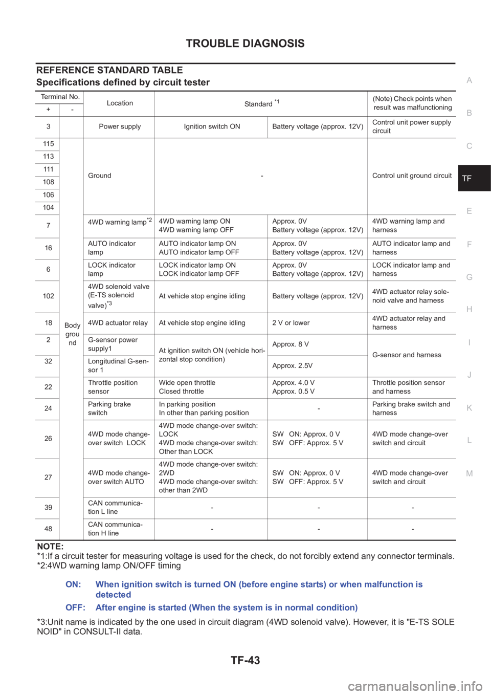
Specifications defined by circuit tester
NOTE:
*1:If a circuit tester for measuring voltage is used for the check, do not forcibly extend any connector terminals.
*2:4WD warning lamp ON/OFF timing
*3:Unit name is indicated by the one used in circuit diagram (4WD solenoid valve). However, it is "E-TS SOLE
NOID" in CONSULT-II data.
Terminal No.
Location
Standard *1(Note) Check points when
result was malfunctioning
+-
3 Power supply Ignition switch ON Battery voltage (approx. 12V)Control unit power supply
circuit
11 5
Body
grou
ndGround - Control unit ground circuit 11 3
111
108
106
104
74WD warning lamp
*24WD warning lamp ON
4WD warning lamp OFFApprox. 0V
Battery voltage (approx. 12V)4WD warning lamp and
harness
16AUTO indicator
lampAUTO indicator lamp ON
AUTO indicator lamp OFFApprox. 0V
Battery voltage (approx. 12V)AUTO indicator lamp and
harness
6LOCK indicator
lampLOCK indicator lamp ON
LOCK indicator lamp OFFApprox. 0V
Battery voltage (approx. 12V)LOCK indicator lamp and
harness
1024WD solenoid valve
(E-TS solenoid
valve)
*3At vehicle stop engine idling Battery voltage (approx. 12V)4WD actuator relay sole-
noid valve and harness
18 4WD actuator relay At vehicle stop engine idling 2 V or lower4WD actuator relay and
harness
2 G-sensor power
supply1
At ignition switch ON (vehicle hori-
zontal stop condition)Approx. 8 V
G-sensor and harness
32 Longitudinal G-sen-
sor 1Approx. 2.5V
22Throttle position
sensorWide open throttle
Closed throttleApprox. 4.0 V
Approx. 0.5 VThrottle position sensor
and harness
24Parking brake
switchIn parking position
In other than parking position-Parking brake switch and
harness
264WD mode change-
over switch LOCK4WD mode change-over switch:
LOCK
4WD mode change-over switch:
Other than LOCKSW ON: Approx. 0 V
SW OFF: Approx. 5 V4WD mode change-over
switch and circuit
274WD mode change-
over switch AUTO4WD mode change-over switch:
2WD
4WD mode change-over switch:
other than 2WDSW ON: Approx. 0 V
SW OFF: Approx. 5 V4WD mode change-over
switch and circuit
39CAN communica-
tion L line---
48CAN communica-
tion H line---
ON: When ignition switch is turned ON (before engine starts) or when malfunction is
detected
OFF: After engine is started (When the system is in normal condition)
Page 2804 of 3833
![NISSAN X-TRAIL 2001 Service Repair Manual BRC-20
[4WD/ABS]
TROUBLE DIAGNOSIS
11 5
Body
groundGround -Control unit ground
path 11 3
111
108
106
104
13 Stop lamp signalDepress the brake pedal.
Release brake pedal.Battery voltage (Approx.
12V NISSAN X-TRAIL 2001 Service Repair Manual BRC-20
[4WD/ABS]
TROUBLE DIAGNOSIS
11 5
Body
groundGround -Control unit ground
path 11 3
111
108
106
104
13 Stop lamp signalDepress the brake pedal.
Release brake pedal.Battery voltage (Approx.
12V](/manual-img/5/57405/w960_57405-2803.png)
BRC-20
[4WD/ABS]
TROUBLE DIAGNOSIS
11 5
Body
groundGround -Control unit ground
path 11 3
111
108
106
104
13 Stop lamp signalDepress the brake pedal.
Release brake pedal.Battery voltage (Approx.
12V)
Approx. 0VStop lamp switch
and path
5ABS MOTOR
RELAYABS motor actuated
(by active test mode of CONSULT-II)
ABS motor stopped (Ignition switch is in
ON)Approx. 2 V or less
Battery voltage (Approx.
12V)ABS motor, motor
relay and harness
17ABS ACTUATOR
RELAYWhen actuator relay is active.
(the engine running)
When actuator relay is inactive.
(In fail-safe mode, before starting
engine)Approx. 2 V or less
Battery voltage (Approx.
12V)ABS actuator relay
and harness
11 6Front RH wheel IN
solenoid
Actuator is activated (by active test
mode of CONSULT-II) or actuator relay
is not activated
(In fail-safe mode, before starting
engine)
Actuator is not activated and actuator
relay is activated (Vehicle stopped with
engine running)Approx. 0V
Battery voltage (Approx.
12V)ABS solenoid valve
path 11 4Front RH wheel
OUT solenoid
11 2Front LH wheel IN
solenoid
11 0Front LH wheel
OUT solenoid
107Rear RH wheel IN
solenoid
105Rear RH wheel
OUT solenoid
103Rear LH wheel IN
solenoid
101Rear LH wheel
OUT solenoid
74WD warning lamp
(Note 2)4WD warning lamp ON
4WD warning lamp OFFApprox. 0V
Battery voltage (Approx.
12V)4WD warning lamp
and harness
4ABS warning lamp
(Note 3)ABS warning lamp ON
ABS warning lamp OFFApprox. 0V
Battery voltage (Approx.
12V)ABS warning lamp
and path
16
AUTO indicator
lampAUTO indicator lamp ON
AUTO indicator lamp OFFApprox. 0V
Battery voltage (Approx.
12V)AUTO indicator
lamp and harness
6LOCK indicator
lampLOCK indicator lamp ON
LOCK indicator lamp OFFApprox. 0V
Battery voltage (Approx.
12V)LOCK indicator
lamp and harness
46 37 FR RH SENSOR
At vehicle rotating (Approx. 30km/
h(19MPH))Pulse generation
Approx. 200HzSpeed sensor and
harness 34 43 FR LH SENSOR
36 45 RR RH SENSOR
44 35 RR LH SENSOR Terminal No.
Location Standard (note 1)(Note) Check
points when result
was malfunctioning +–
Page 3053 of 3833

BL-1
BODY, LOCK & SECURITY SYSTEM
I BODY
CONTENTS
C
D
E
F
G
H
J
K
L
M
SECTION
A
B
BL
BODY, LOCK & SECURITY SYSTEM
PRECAUTIONS .......................................................... 3
Precautions for Supplemental Restraint System
(SRS) “AIR BAG” and “SEAT BELT PRE-TEN-
SIONER” .................................................................. 3
Precautions .............................................................. 3
HOOD ......................................................................... 4
Fitting Adjustment .................................................... 4
FRONT END HEIGHT ADJUSTMENT AND LAT-
ERAL/LONGITUDINAL CLEARANCE ADJUST-
MENT .................................................................... 4
SURFACE HEIGHT ADJUSTMENT ..................... 4
Removal and Installation of Hood Assembly ............ 5
Removal and Installation of Hood Lock Control ....... 6
REMOVAL ............................................................. 6
INSTALLATION ..................................................... 7
Hood Lock Control Inspection .................................. 7
DOOR ......................................................................... 8
Fitting Adjustment .................................................... 8
FRONT DOOR ...................................................... 8
REAR DOOR ........................................................ 8
STRIKER ADJUSTMENT ..................................... 8
Removal and Installation .......................................... 9
Door Weatherstrip .................................................. 10
POWER DOOR LOCK SYSTEM ...............................11
System Description ................................................. 11
OPERATION ........................................................ 11
Component Parts and Harness Connector Location .... 11
Schematic .............................................................. 12
Wiring Diagram — D/LOCK — ............................... 13
Terminal and Reference Value for Time Control Unit ... 17
Symptom Chart ...................................................... 18
Power Supply and Ground Circuit Check ............... 18
Door Lock/Unlock Switch Check ............................ 19
Door Key Cylinder Switch Check ........................... 20
Front Door Lock Actuator (Driver Side) Check ....... 21
Front Door Lock Actuator (Passenger Side) Check ... 22
Rear Door Lock Actuator LH Check ....................... 23
Rear Door Lock Actuator RH Check ...................... 24
Back Door Lock Actuator Check ............................ 25
Door Switch Check ................................................. 26Door Unlock Sensor Check .................................... 26
Key Switch Check ................................................... 27
POWER DOOR LOCK — SUPER LOCK — ............ 29
System Description ................................................. 29
OUTLINE ............................................................. 29
OPERATION .....................................................
... 29
Schematic ............................................................... 31
Wiring Diagram — S/LOCK — ............................... 32
Terminal and Reference Value for Time Control Unit ... 38
Trouble Diagnoses ................................................. 39
PRELIMINARY CHECK ....................................... 39
SYMPTOM CHART ............................................. 40
Power Supply and Ground Circuit Check ............... 41
Door Lock/Unlock Switch Check ............................ 42
Door Key Cylinder Switch Check ............................ 43
Front Door Lock Actuator (Driver Side) Check ....... 44
Front Door Lock Actuator (Passenger Side) Check ... 45
Rear Door Lock Actuator LH Check ....................... 46
Rear Door Lock Actuator RH Check ....................... 47
Back Door Lock Actuator Check ............................. 48
Door Switch Check ................................................. 49
Door Unlock Sensor Check .................................... 50
Key Switch Check ................................................... 51
Super Lock Actuator Check .................................... 52
NATS Release Signal Check .................................. 53
Ignition Switch “ON” Circuit Check ......................... 54
MULTI-REMOTE CONTROL SYSTEM ..................... 55
Component Parts and Harness Connector Location ... 55
System Description ................................................. 56
FUNCTION .......................................................... 56
LOCK OPERATION ............................................. 56
UNLOCK OPERATION ........................................ 56
HAZARD REMINDER ......................................... 56
MULTI-REMOTE CONTROLLER ID CODE
ENTRY ................................................................ 56
Wiring Diagram — MULTI — .................................. 57
Terminal and Reference Value for Multi-remote
Control Unit ............................................................. 59
Symptom Chart ....................................................... 59
Remote Controller Battery Check ........................... 59
Page 3054 of 3833

BL-2
Power Supply and Ground Circuit Check ............... 60
Time Control Unit Lock Signal Circuit Check .......... 61
Time Control Unit Unlock Signal Circuit Check ...... 62
Hazard Reminder Check ........................................ 62
ID Code Entry Procedure ....................................... 63
Remote Controller Battery Replacement ................ 64
FRONT DOOR LOCK ............................................... 65
Component Parts Location ..................................... 65
Inspection and Adjustment ..................................... 65
OUT SIDE HANDLE ROD ADJUSTMENT .......... 65
Removal and Installation ........................................ 65
REMOVAL ........................................................... 65
INSTALLATION .................................................... 66
Disassembly and Assembly .................................... 67
DISASSEMBLY ................................................... 67
ASSEMBLY ......................................................... 67
REAR DOOR LOCK .................................................. 68
Component Parts Location ..................................... 68
Inspection and Adjustment ..................................... 68
OUT SIDE HANDLE ROD ADJUSTMENT .......... 68
Removal and Installation ........................................ 68
REMOVAL ........................................................... 68
INSTALLATION .................................................... 69
Disassembly and Assembly .................................... 70
DISASSEMBLY ................................................... 70
ASSEMBLY ......................................................... 70
BACK DOOR ............................................................. 71
Fitting Adjustment ................................................... 71
VERTICAL/LATERAL CLEARANCE ADJUST-
MENT .................................................................. 71
Back Door Assembly .............................................. 72
REMOVAL AND INSTALLATION ......................... 72
INSPECTION ....................................................... 72
Removal and Installation of Back Door Handle ...... 72
Removal and Installation of Back Door Lock and Actuator ................................................................... 73
Removal and Installation of Back Door Weatherstrip ... 73
FUEL FILLER LID OPENER ..................................... 75
Component Parts Location ..................................... 75
THEFT WARNING SYSTEM ..................................... 76
Wiring Diagram — THEFT —/PRI-WIRE ................ 76
LHD MODELS ...................................................... 76
RHD MODELS ..................................................... 78
NATS (NISSAN ANTI-THEFT SYSTEM) ................... 80
Component Parts and Harness Connector Location ... 80
System Description ................................................. 81
System Composition ............................................... 82
Wiring Diagram — NATS — .................................... 83
GASOLINE ENGINE MODELS ............................ 83
DIESEL ENGINE MODELS ................................. 84
CONSULT-II ............................................................ 85
CONSULT-II INSPECTION PROCEDURE .......... 85
CONSULT-II DIAGNOSTIC TEST MODE FUNC-
TION .................................................................... 85
HOW TO READ SELF-DIAGNOSTIC RESULTS ... 86
NATS SELF-DIAGNOSTIC RESULTS ITEM
CHART ................................................................. 86
Work Flow ............................................................... 88
Trouble Diagnoses .................................................. 89
SYMPTOM MATRIX CHART 1 ............................ 89
SYMPTOM MATRIX CHART 2 ............................ 90
DIAGNOSTIC SYSTEM DIAGRAM ..................... 90
Diagnostic Procedure 1 ........................................... 91
Diagnostic Procedure 2 ........................................... 91
Diagnostic Procedure 3 ........................................... 94
Diagnostic Procedure 4 ........................................... 95
Diagnostic Procedure 5 ........................................... 96
Diagnostic Procedure 6 ........................................... 97
Diagnostic Procedure 7 ........................................... 98
Diagnostic Procedure 8 ........................................... 99
How to Replace NATS IMMU ................................100