2001 NISSAN X-TRAIL flat tire
[x] Cancel search: flat tirePage 2654 of 3833
TF-44
TROUBLE DIAGNOSIS
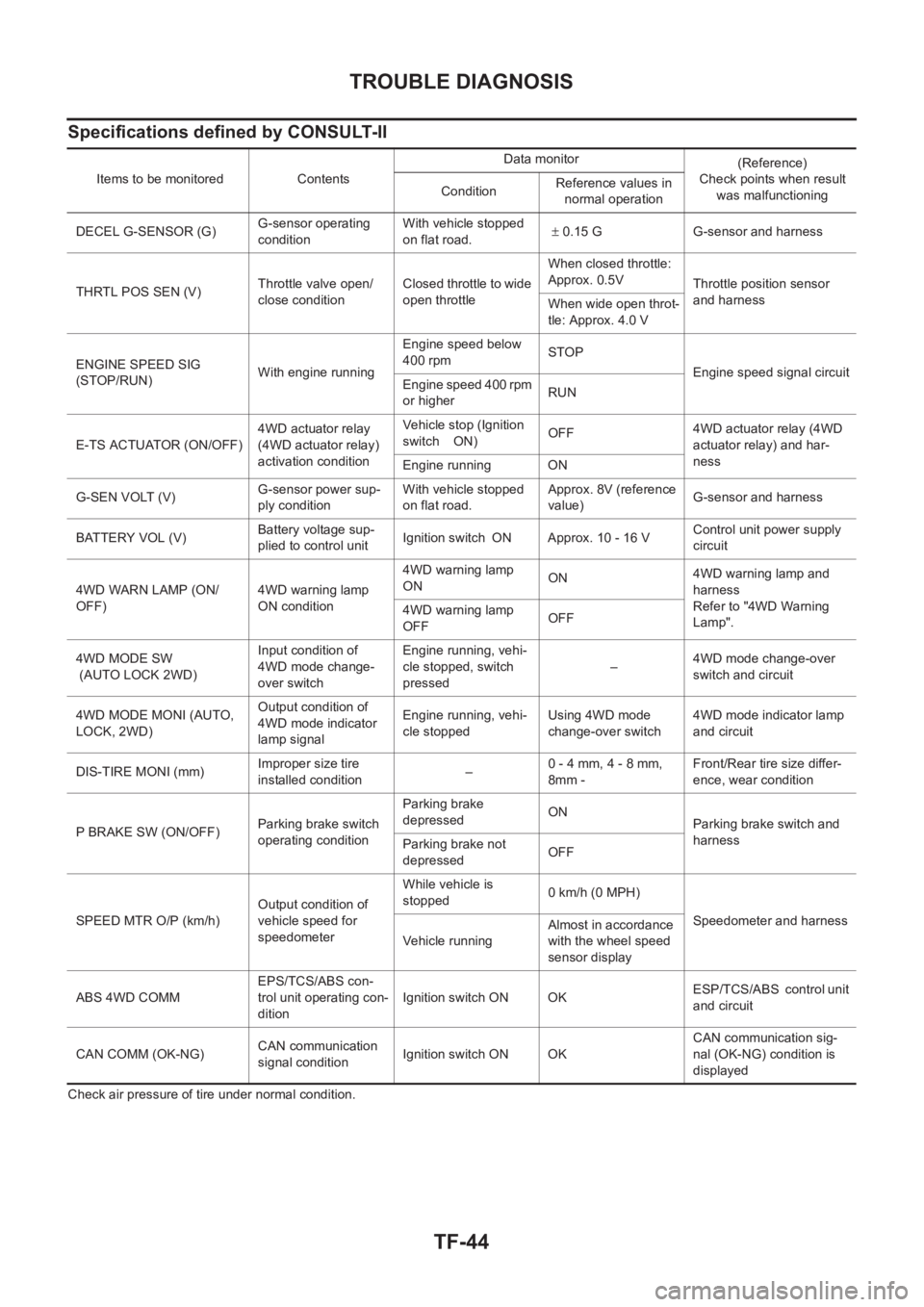
Specifications defined by CONSULT-II
Check air pressure of tire under normal condition.Items to be monitored ContentsData monitor
(Reference)
Check points when result
was malfunctioning ConditionReference values in
normal operation
DECEL G-SENSOR (G)G-sensor operating
conditionWith vehicle stopped
on flat road.± 0.15 G G-sensor and harness
THRTL POS SEN (V)Throttle valve open/
close conditionClosed throttle to wide
open throttleWhen closed throttle:
Approx. 0.5V
Throttle position sensor
and harness
When wide open throt-
tle: Approx. 4.0 V
ENGINE SPEED SIG
(STOP/RUN)With engine runningEngine speed below
400 rpmSTOP
Engine speed signal circuit
Engine speed 400 rpm
or higherRUN
E-TS ACTUATOR (ON/OFF)4WD actuator relay
(4WD actuator relay)
activation conditionVehicle stop (Ignition
switch ON)OFF4WD actuator relay (4WD
actuator relay) and har-
ness
Engine running ON
G-SEN VOLT (V)G-sensor power sup-
ply conditionWith vehicle stopped
on flat road.Approx. 8V (reference
value)G-sensor and harness
BATTERY VOL (V)Battery voltage sup-
plied to control unitIgnition switch ON Approx. 10 - 16 VControl unit power supply
circuit
4WD WARN LAMP (ON/
OFF)4WD warning lamp
ON condition4WD warning lamp
ONON4WD warning lamp and
harness
Refer to "4WD Warning
Lamp". 4WD warning lamp
OFFOFF
4WD MODE SW
(AUTO LOCK 2WD)Input condition of
4WD mode change-
over switchEngine running, vehi-
cle stopped, switch
pressed–4WD mode change-over
switch and circuit
4WD MODE MONI (AUTO,
LOCK, 2WD)Output condition of
4WD mode indicator
lamp signalEngine running, vehi-
cle stoppedUsing 4WD mode
change-over switch4WD mode indicator lamp
and circuit
DIS-TIRE MONI (mm)Improper size tire
installed condition
–0 - 4 mm, 4 - 8 mm,
8mm -Front/Rear tire size differ-
ence, wear condition
P BRAKE SW (ON/OFF)Parking brake switch
operating conditionParking brake
depressedON
Parking brake switch and
harness
Parking brake not
depressedOFF
SPEED MTR O/P (km/h)Output condition of
vehicle speed for
speedometerWhile vehicle is
stopped 0 km/h (0 MPH)
Speedometer and harness
Ve h i c le r u n n in gAlmost in accordance
with the wheel speed
sensor display
ABS 4WD COMMEPS/TCS/ABS con-
trol unit operating con-
ditionIgnition switch ON OKESP/TCS/ABS control unit
and circuit
CAN COMM (OK-NG)CAN communication
signal conditionIgnition switch ON OKCAN communication sig-
nal (OK-NG) condition is
displayed
Page 2708 of 3833
FSU-2
PRECAUTIONS
PRECAUTIONS
PFP:00001
CautionEES0006Z
●When installing rubber bushings, final tightening must be carried out under unladen conditions with tires
on flat, level ground. Oil will shorten the life of rubber bushings. Be sure to wipe off any spilled oil.
●“Unladen condition” means that fuel, coolant and lubricant are full and ready for drive. However, spare tire,
jack, and hand tools should be unloaded.
●After installing the removed suspension parts, always check wheel alignment and adjust if necessary.
●Replace the caulking nut with a new one. Install a new nut without wiping the oil off before tightening.
Page 2713 of 3833
FRONT SUSPENSION ASSEMBLY
FSU-7
C
D
F
G
H
I
J
K
L
MA
B
FSU
To e - i n
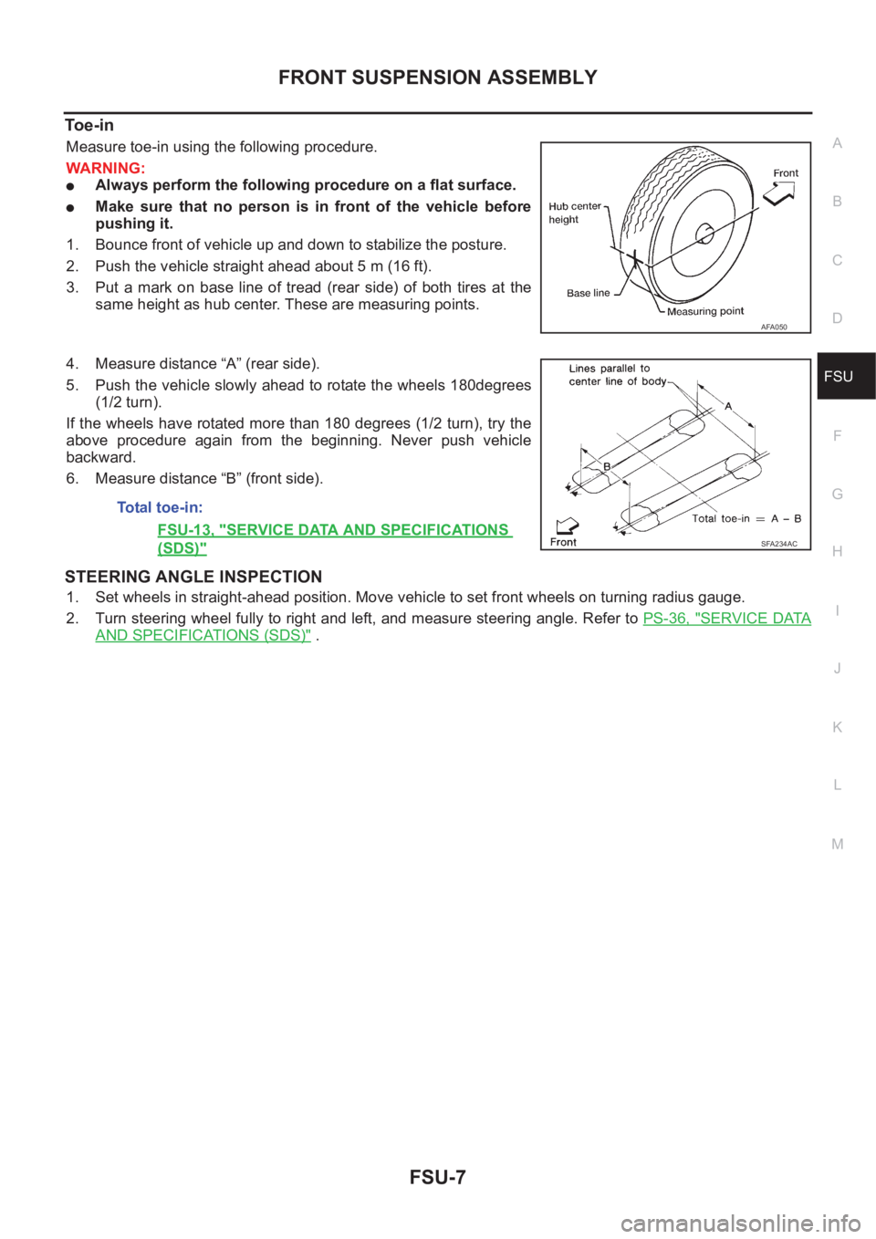
Measure toe-in using the following procedure.
WARNING:
●Always perform the following procedure on a flat surface.
●Make sure that no person is in front of the vehicle before
pushing it.
1. Bounce front of vehicle up and down to stabilize the posture.
2. Push the vehicle straight ahead about 5 m (16 ft).
3. Put a mark on base line of tread (rear side) of both tires at the
same height as hub center. These are measuring points.
4. Measure distance “A” (rear side).
5. Push the vehicle slowly ahead to rotate the wheels 180degrees
(1/2 turn).
If the wheels have rotated more than 180 degrees (1/2 turn), try the
above procedure again from the beginning. Never push vehicle
backward.
6. Measure distance “B” (front side).
STEERING ANGLE INSPECTION
1. Set wheels in straight-ahead position. Move vehicle to set front wheels on turning radius gauge.
2. Turn steering wheel fully to right and left, and measure steering angle. Refer to PS-36, "
SERVICE DATA
AND SPECIFICATIONS (SDS)" .
AFA050
Total toe-in:
FSU-13, "
SERVICE DATA AND SPECIFICATIONS
(SDS)"SFA234AC
Page 2716 of 3833
FSU-10
TRANSVERSE LINK
TRANSVERSE LINK
PFP:54500
Removal and InstallationEES00076
REMOVAL
1. Remove steering knuckle from transverse link. Refer toFAX-7, "REMOVAL" .
2. Remove mounting nuts and washers on lower portion of stabilizer connecting rod.
3. Slightly loosen transverse link mounting bolts.
4. Remove transverse link mounting bolts and nuts, and remove transverse link from suspension member.
INSPECTION AFTER REMOVAL
Visual Inspection
Check transverse link and bushing for deformation, cracks, and other damage. Replace the entire transverse
link assembly if cracks, deformation or any other damage is found.
Ball Joint Inspection
CAUTION:
Before measurement, move the ball joint at least ten times by hand to check for smooth movement.
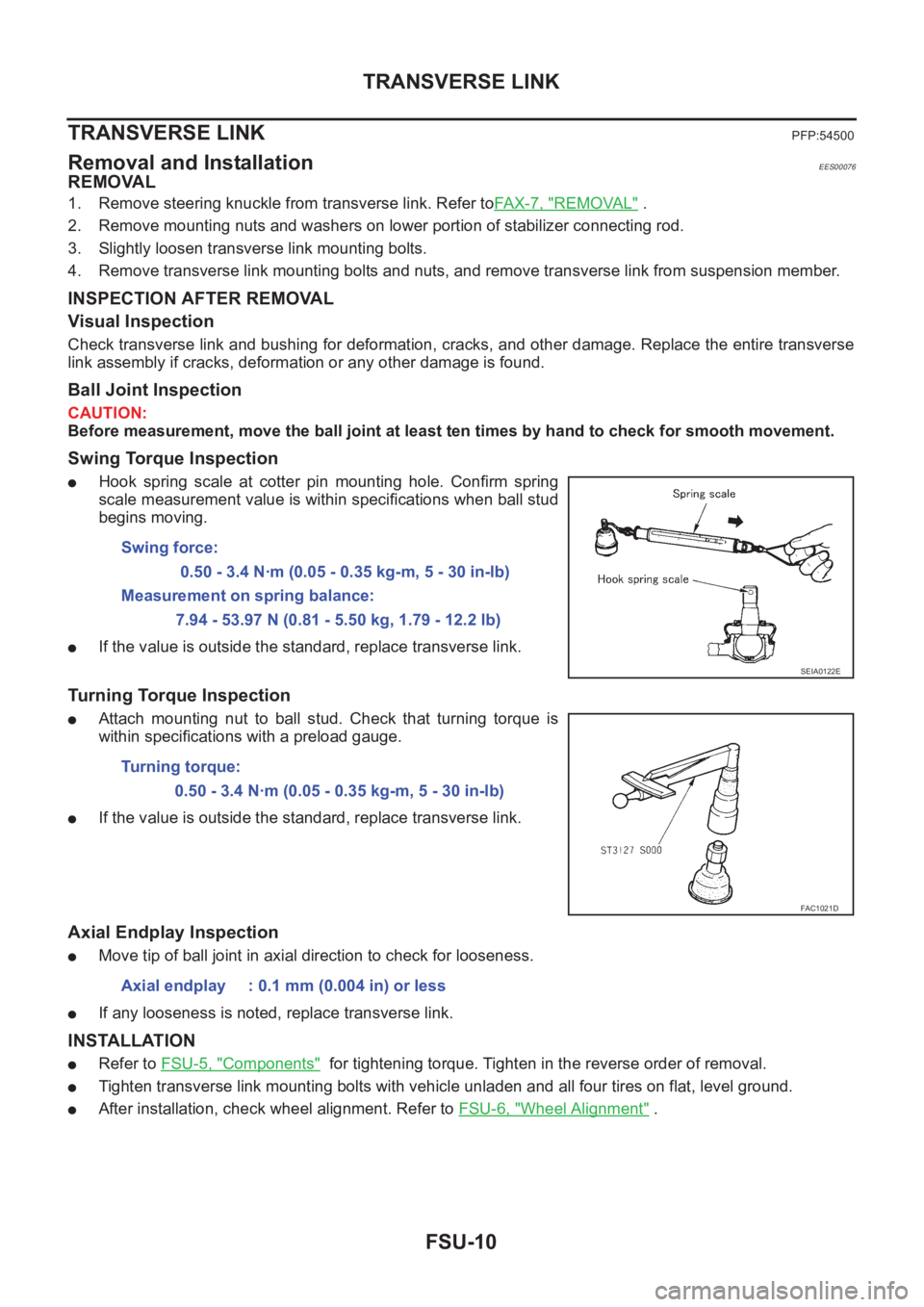
Swing Torque Inspection
●Hook spring scale at cotter pin mounting hole. Confirm spring
scale measurement value is within specifications when ball stud
begins moving.
●If the value is outside the standard, replace transverse link.
Turning Torque Inspection
●Attach mounting nut to ball stud. Check that turning torque is
within specifications with a preload gauge.
●If the value is outside the standard, replace transverse link.
Axial Endplay Inspection
●Move tip of ball joint in axial direction to check for looseness.
●If any looseness is noted, replace transverse link.
INSTALLATION
●Refer to FSU-5, "Components" for tightening torque. Tighten in the reverse order of removal.
●Tighten transverse link mounting bolts with vehicle unladen and all four tires on flat, level ground.
●After installation, check wheel alignment. Refer to FSU-6, "Wheel Alignment" . Swing force:
0.50 - 3.4 N·m (0.05 - 0.35 kg-m, 5 - 30 in-lb)
Measurement on spring balance:
7.94 - 53.97 N (0.81 - 5.50 kg, 1.79 - 12.2 lb)
SEIA0122E
Turning torque:
0.50 - 3.4 N·m (0.05 - 0.35 kg-m, 5 - 30 in-lb)
FAC1021D
Axial endplay : 0.1 mm (0.004 in) or less
Page 2726 of 3833
RSU-6
REAR SUSPENSION ASSEMBLY
On-Vehicle Inspection and Service
EES0007F
Check axle and suspension parts for excessive play, wear, and damage.
●Move rear wheels (RH/LH) to check abnormal free play.
●Retighten all nuts and bolts to the specified torque.
●Check strut for oil leakage and damage.
Wheel AlignmentEES0007G
DESCRIPTION
●Measure wheel alignment under unladen conditions. “Unladen conditions” means that fuel, coolant, and
lubricant are full. However, spare tire, jack, and hand tools should be unloaded.
PRELIMINARY INSPECTION
1. Check the tires for improper air pressure and wear.
2. Check road wheels for runout.
3. Check wheel bearing axial endplay.
4. Check strut operation.
5. Check each mounting point of axle and suspension for looseness and deformation.
6. Check each link and arm for cracks, deformation, and other damage.
7. Check the vehicle posture.
CAMBER
Camber is preset at factory and cannot be adjusted.
●If the camber is not within specification, inspect and replace any damaged or worn rear suspension parts.
TOE-IN
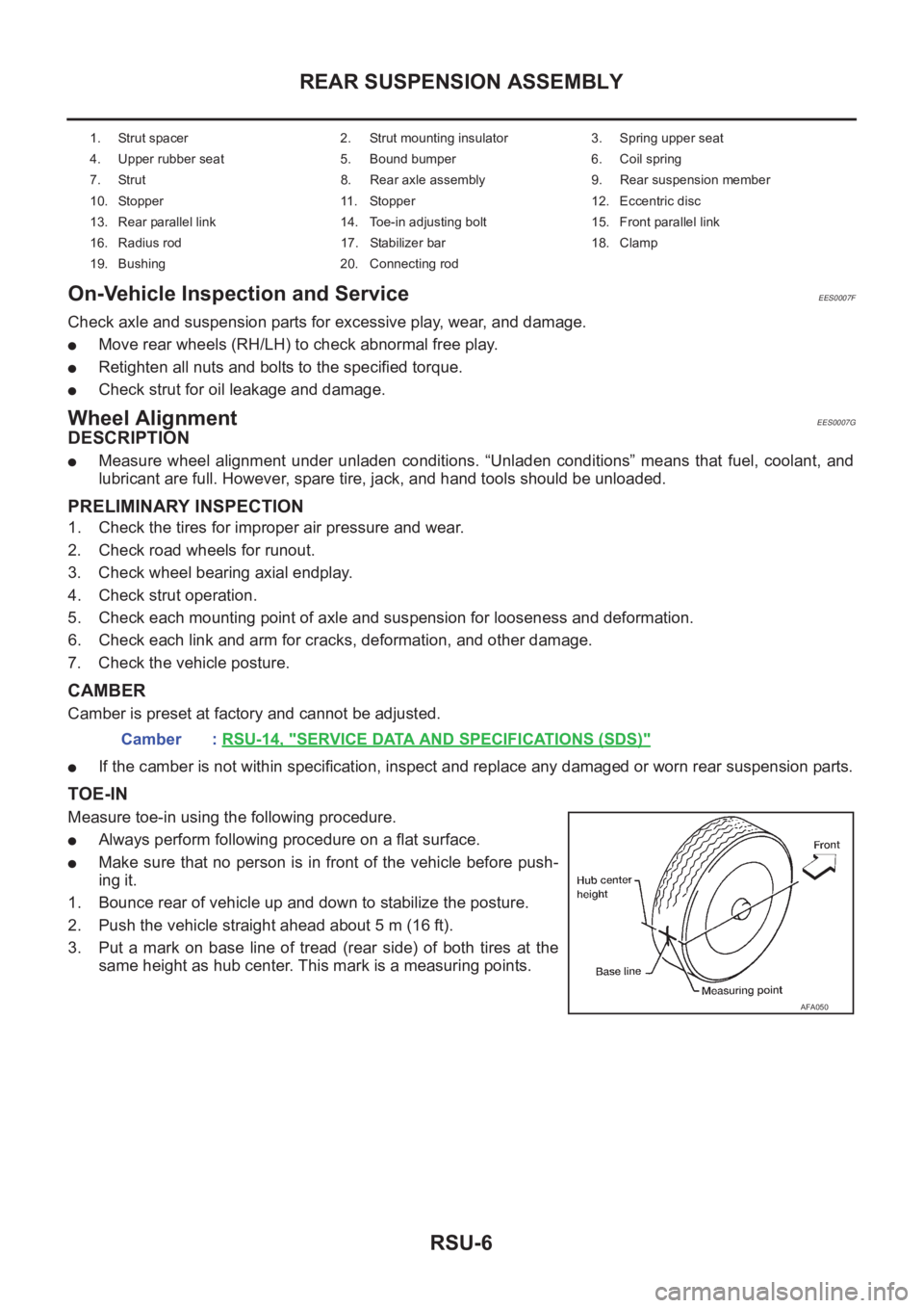
Measure toe-in using the following procedure.
●Always perform following procedure on a flat surface.
●Make sure that no person is in front of the vehicle before push-
ing it.
1. Bounce rear of vehicle up and down to stabilize the posture.
2. Push the vehicle straight ahead about 5 m (16 ft).
3. Put a mark on base line of tread (rear side) of both tires at the
same height as hub center. This mark is a measuring points.
1. Strut spacer 2. Strut mounting insulator 3. Spring upper seat
4. Upper rubber seat 5. Bound bumper 6. Coil spring
7. Strut 8. Rear axle assembly 9. Rear suspension member
10. Stopper 11. Stopper 12. Eccentric disc
13. Rear parallel link 14. Toe-in adjusting bolt 15. Front parallel link
16. Radius rod 17. Stabilizer bar 18. Clamp
19. Bushing 20. Connecting rod
Camber : RSU-14, "SERVICE DATA AND SPECIFICATIONS (SDS)"
AFA050
Page 2737 of 3833
ROAD WHEEL
WT-3
C
D
F
G
H
I
J
K
L
MA
B
WT
ROAD WHEELPFP:40300
InspectionEES000J2
ALUMINUM WHEEL
1. Check tires for wear and improper inflation.
2. Check wheels for deformation, cracks and other damage. If
deformed, remove wheel and check wheel runout.
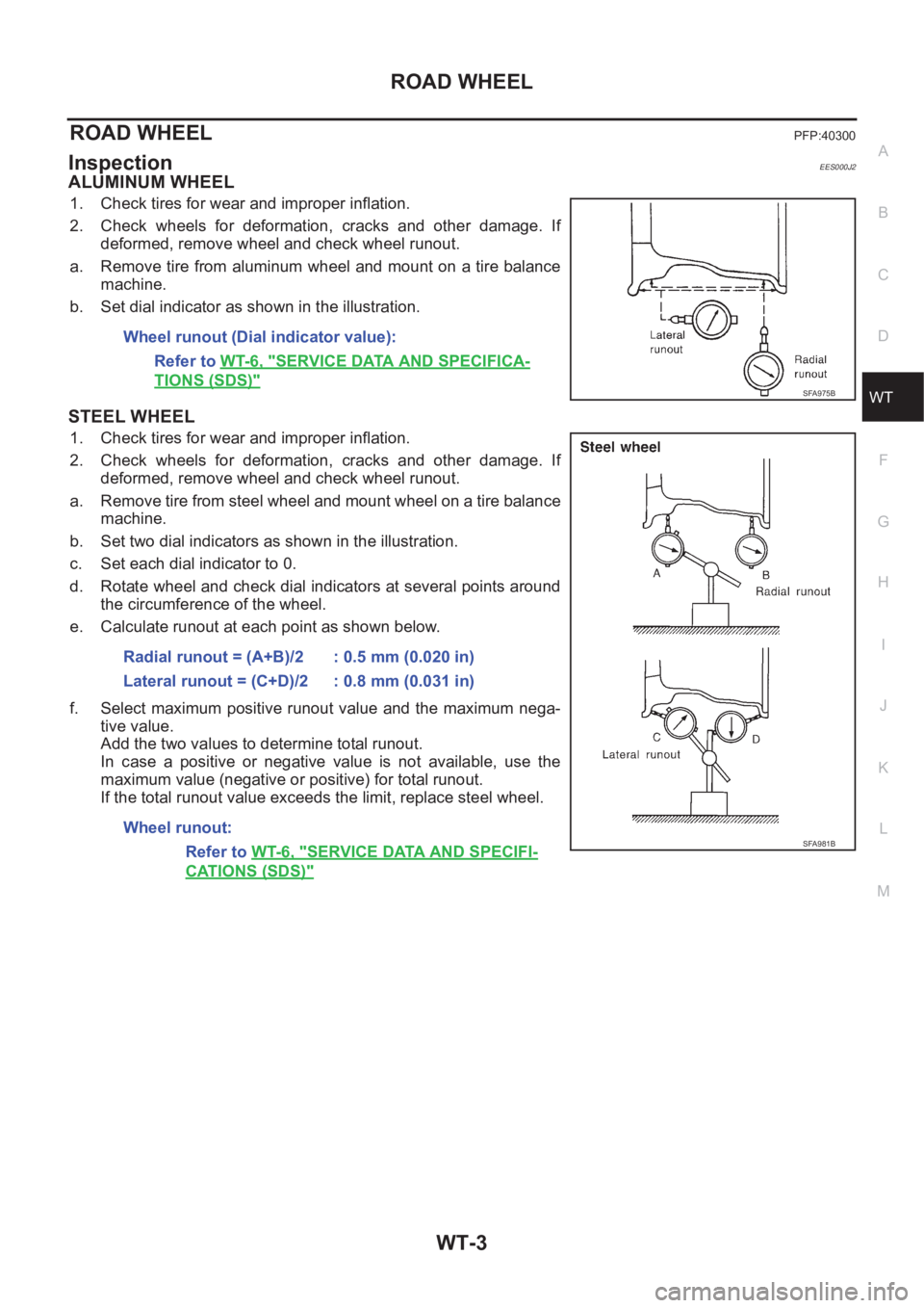
a. Remove tire from aluminum wheel and mount on a tire balance
machine.
b. Set dial indicator as shown in the illustration.
STEEL WHEEL
1. Check tires for wear and improper inflation.
2. Check wheels for deformation, cracks and other damage. If
deformed, remove wheel and check wheel runout.
a. Remove tire from steel wheel and mount wheel on a tire balance
machine.
b. Set two dial indicators as shown in the illustration.
c. Set each dial indicator to 0.
d. Rotate wheel and check dial indicators at several points around
the circumference of the wheel.
e. Calculate runout at each point as shown below.
f. Select maximum positive runout value and the maximum nega-
tive value.
Add the two values to determine total runout.
In case a positive or negative value is not available, use the
maximum value (negative or positive) for total runout.
If the total runout value exceeds the limit, replace steel wheel. Wheel runout (Dial indicator value):
Refer to WT-6, "
SERVICE DATA AND SPECIFICA-
TIONS (SDS)"SFA975B
Radial runout = (A+B)/2 : 0.5 mm (0.020 in)
Lateral runout = (C+D)/2 : 0.8 mm (0.031 in)
Wheel runout:
Refer to WT-6, "
SERVICE DATA AND SPECIFI-
CATIONS (SDS)"
SFA981B
Page 2739 of 3833
ROAD WHEEL TIRE ASSEMBLY
WT-5
C
D
F
G
H
I
J
K
L
MA
B
WT
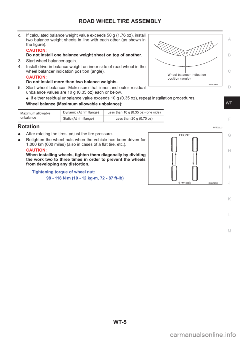
c. If calculated balance weight value exceeds 50 g (1.76 oz), install
two balance weight sheets in line with each other (as shown in
the figure).
CAUTION:
Do not install one balance weight sheet on top of another.
3. Start wheel balancer again.
4. Install drive-in balance weight on inner side of road wheel in the
wheel balancer indication position (angle).
CAUTION:
Do not install more than two balance weights.
5. Start wheel balancer. Make sure that inner and outer residual
unbalance values are 10 g (0.35 oz) each or below.
●If either residual unbalance value exceeds 10 g (0.35 oz), repeat installation procedures.
Wheel balance (Maximum allowable unbalance):
RotationEES000J3
●After rotating the tires, adjust the tire pressure.
●Retighten the wheel nuts when the vehicle has been driven for
1,000 km (600 miles) (also in cases of a flat tire, etc.).
CAUTION:
When installing wheels, tighten them diagonally by dividing
the work two to three times in order to prevent the wheels
from developing any distortion.
Maximum allowable
unbalanceDynamic (At rim flange) Less than 10 g (0.35 oz) (one side)
Static (At rim flange) Less than 20 g (0.70 oz)
SMA056D
Tightening torque of wheel nut:
98 - 118 N·m (10 - 12 kg-m, 72 - 87 ft-lb)
SMA829C
Page 3005 of 3833
PRECAUTIONS
SRS-3
C
D
E
F
G
I
J
K
L
MA
B
SRS
PRECAUTIONSPFP:00001
Precautions for Supplemental Restraint System (SRS) “AIR BAG” and “SEAT
BELT PRE-TENSIONER”
EHS000QI
The Supplemental Restraint System such as “AIR BAG” and “SEAT BELT PRE-TENSIONER”, used along
with a front seat belt, helps to reduce the risk or severity of injury to the driver and front passenger for certain
types of collision. Information necessary to service the system safely is included in the SRS and SB section of
this Service Manual.
WARNING:
●To avoid rendering the SRS inoperative, which could increase the risk of personal injury or death
in the event of a collision which would result in air bag inflation, all maintenance must be per-
formed by an authorized NISSAN/INFINITI dealer.
●Improper maintenance, including incorrect removal and installation of the SRS, can lead to per-
sonal injury caused by unintentional activation of the system. For removal of Spiral Cable and Air
Bag Module, see the SRS section.
●Do not use electrical test equipment on any circuit related to the SRS unless instructed to in this
Service Manual. SRS wiring harnesses can be identified by yellow and/or orange harness connec-
tors.
Precautions for SRS “AIR BAG” and “SEAT BELT PRE-TENSIONER” ServiceEHS000BH
●Do not use electrical test equipment to check SRS circuits unless instructed to in this Service Manual.
●Before servicing the SRS, turn ignition switch “OFF”, disconnect both battery cables and wait at least 3
minutes.
For approximately 3 minutes after the cables is removed, it is still possible for the air bag and seat belt
pre-tensioner to deploy. Therefore, do not work on any SRS connectors or wires until at least 3 minutes
have passed.
●Diagnosis sensor unit must always be installed with their arrow marks “⇐” pointing towards the front of the
vehicle for proper operation. Also check diagnosis sensor unit for cracks, deformities or rust before instal-
lation and replace as required.
●The spiral cable must be aligned with the neutral position since its rotations are limited. Do not attempt to
turn steering wheel or column after removal of steering gear.
●Handle air bag module carefully. Always place driver and front passenger air bag modules with the pad
side facing upward and place front side air bag module standing with stud bolt side setting bottom.
●Conduct self-diagnosis to check entire SRS for proper function after replacing any components.
●After air bag inflates, the front instrument panel assembly should be replaced if damaged.
Trouble Diagnosis PrecautionEHS000BI
When you read wiring diagrams, refer to the followings:
●“HOW TO READ WIRING DIAGRAMS” in GI section
●PG-2, "POWER SUPPLY ROUTING" in PG section
When you perform trouble diagnosis, refer to the followings:
●“HOW TO FOLLOW TEST GROUP IN TROUBLE DIAGNOSIS” in GI section
●“HOW TO PERFORM EFFICIENT DIAGNOSIS FOR AN ELECTRICAL INCIDENT” in GI section
Check for any service bulletins before servicing the vehicle.