2001 NISSAN X-TRAIL overheating
[x] Cancel search: overheatingPage 307 of 3833

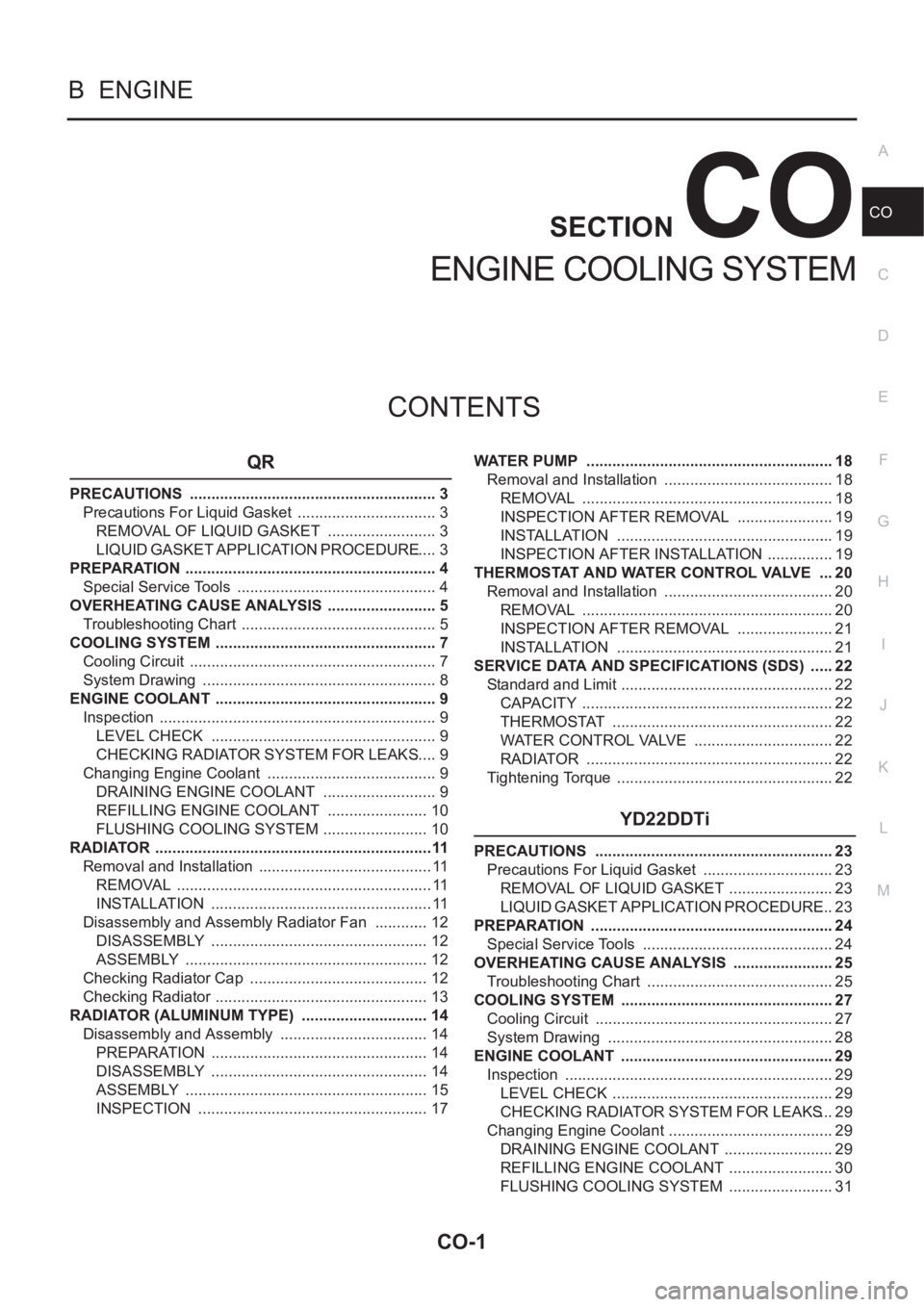
CO-1
ENGINE COOLING SYSTEM
B ENGINE
CONTENTS
C
D
E
F
G
H
I
J
K
L
M
SECTION
A
CO
ENGINE COOLING SYSTEM
QR
PRECAUTIONS .......................................................... 3
Precautions For Liquid Gasket ................................. 3
REMOVAL OF LIQUID GASKET .......................... 3
LIQUID GASKET APPLICATION PROCEDURE ..... 3
PREPARATION ........................................................... 4
Special Service Tools ............................................... 4
OVERHEATING CAUSE ANALYSIS .......................... 5
Troubleshooting Chart .............................................. 5
COOLING SYSTEM .................................................... 7
Cooling Circuit .......................................................... 7
System Drawing ....................................................... 8
ENGINE COOLANT .................................................... 9
Inspection ................................................................. 9
LEVEL CHECK ..................................................... 9
CHECKING RADIATOR SYSTEM FOR LEAKS ..... 9
Changing Engine Coolant ........................................ 9
DRAINING ENGINE COOLANT ........................... 9
REFILLING ENGINE COOLANT ........................ 10
FLUSHING COOLING SYSTEM ......................... 10
RADIATOR .................................................................11
Removal and Installation ......................................... 11
REMOVAL ............................................................ 11
INSTALLATION .................................................... 11
Disassembly and Assembly Radiator Fan ............. 12
DISASSEMBLY ................................................... 12
ASSEMBLY ......................................................... 12
Checking Radiator Cap .......................................... 12
Checking Radiator .................................................. 13
RADIATOR (ALUMINUM TYPE) .............................. 14
Disassembly and Assembly ................................... 14
PREPARATION ................................................... 14
DISASSEMBLY ................................................... 14
ASSEMBLY ......................................................... 15
INSPECTION ...................................................... 17WATER PUMP .......................................................... 18
Removal and Installation ........................................ 18
REMOVAL ........................................................... 18
INSPECTION AFTER REMOVAL ....................... 19
INSTALLATION ................................................... 19
INSPECTION AFTER INSTALLATION ................ 19
THERMOSTAT AND WATER CONTROL VALVE .... 20
Removal and Installation ........................................ 20
REMOVAL ........................................................... 20
INSPECTION AFTER REMOVAL ....................... 21
INSTALLATION ................................................
... 21
SERVICE DATA AND SPECIFICATIONS (SDS) ...... 22
Standard and Limit .................................................. 22
CAPACITY ........................................................... 22
THERMOSTAT .................................................... 22
WATER CONTROL VALVE ................................. 22
RADIATOR ....................................................... ... 22
Tightening Torque ................................................... 22
YD22DDTi
PRECAUTIONS ........................................................ 23
Precautions For Liquid Gasket ............................... 23
REMOVAL OF LIQUID GASKET ......................... 23
LIQUID GASKET APPLICATION PROCEDURE ... 23
PREPARATION ......................................................... 24
Special Service Tools ............................................. 24
OVERHEATING CAUSE ANALYSIS ........................ 25
Troubleshooting Chart ............................................ 25
COOLING SYSTEM .................................................. 27
Cooling Circuit ........................................................ 27
System Drawing ..................................................... 28
ENGINE COOLANT .................................................. 29
Inspection ............................................................... 29
LEVEL CHECK .................................................... 29
CHECKING RADIATOR SYSTEM FOR LEAKS ... 29
Changing Engine Coolant ....................................... 29
DRAINING ENGINE COOLANT .......................... 29
REFILLING ENGINE COOLANT ......................... 30
FLUSHING COOLING SYSTEM ......................... 31
Page 311 of 3833
![NISSAN X-TRAIL 2001 Service Repair Manual OVERHEATING CAUSE ANALYSIS
CO-5
[QR]
C
D
E
F
G
H
I
J
K
L
MA
CO
OVERHEATING CAUSE ANALYSISPFP:00012
Troubleshooting ChartEBS00KOD
Symptom Check items
Cooling sys-
tem parts
malfunctionPoor heat transf NISSAN X-TRAIL 2001 Service Repair Manual OVERHEATING CAUSE ANALYSIS
CO-5
[QR]
C
D
E
F
G
H
I
J
K
L
MA
CO
OVERHEATING CAUSE ANALYSISPFP:00012
Troubleshooting ChartEBS00KOD
Symptom Check items
Cooling sys-
tem parts
malfunctionPoor heat transf](/manual-img/5/57405/w960_57405-310.png)
OVERHEATING CAUSE ANALYSIS
CO-5
[QR]
C
D
E
F
G
H
I
J
K
L
MA
CO
OVERHEATING CAUSE ANALYSISPFP:00012
Troubleshooting ChartEBS00KOD
Symptom Check items
Cooling sys-
tem parts
malfunctionPoor heat transferWater pump malfunction Worn or loose drive belt
— Thermostat stuck closed —
Damaged finsDust contamination or
paper clogging
Physical damage
Clogged radiator cooling
tubeExcess foreign material
(rust, dirt, sand, etc.)
Reduced air flowCooling fan does not oper-
ate
Fan assembly — High resistance to fan rota-
tion
Damaged fan blades
Damaged radiator shroud — — —
Improper engine coolant
mixture ratio—— —
Poor engine coolant quality — Engine coolant viscosity —
Insufficient engine coolantEngine coolant leaksCooling hoseLoose clamp
Cracked hose
Water pump Poor sealing
Radiator capLoose
Poor sealing
RadiatorO-ring for damage, deterio-
ration or improper fitting
Cracked radiator tank
Cracked radiator core
Reservoir tank Cracked reservoir tank
Overflowing reservoir tankExhaust gas leaks into
cooling systemCylinder head deterioration
Cylinder head gasket dete-
rioration
Page 312 of 3833
![NISSAN X-TRAIL 2001 Service Repair Manual CO-6
[QR]
OVERHEATING CAUSE ANALYSIS
Except cool-
ing system
parts mal-
function— Overload on engineAbusive drivingHigh engine rpm under no
load
Driving in low gear for
extended time
Driving at e NISSAN X-TRAIL 2001 Service Repair Manual CO-6
[QR]
OVERHEATING CAUSE ANALYSIS
Except cool-
ing system
parts mal-
function— Overload on engineAbusive drivingHigh engine rpm under no
load
Driving in low gear for
extended time
Driving at e](/manual-img/5/57405/w960_57405-311.png)
CO-6
[QR]
OVERHEATING CAUSE ANALYSIS
Except cool-
ing system
parts mal-
function— Overload on engineAbusive drivingHigh engine rpm under no
load
Driving in low gear for
extended time
Driving at extremely high
speed
Powertrain system mal-
function
— Installed improper size
wheels and tires
Dragging brakes
Improper ignition timing
Blocked or restricted air
flowBlocked bumper —
— Blocked radiator grilleInstalled car brassiere
Mud contamination or
paper clogging
Blocked radiator —
Blocked condenser
Blocked air flow
Installed large fog lamp Symptom Check items
Page 331 of 3833
![NISSAN X-TRAIL 2001 Service Repair Manual OVERHEATING CAUSE ANALYSIS
CO-25
[YD22DDTi]
C
D
E
F
G
H
I
J
K
L
MA
CO
OVERHEATING CAUSE ANALYSISPFP:00012
Troubleshooting ChartEBS00BAW
Symptom Check items
Cooling sys-
tem parts
malfunctionPoor heat NISSAN X-TRAIL 2001 Service Repair Manual OVERHEATING CAUSE ANALYSIS
CO-25
[YD22DDTi]
C
D
E
F
G
H
I
J
K
L
MA
CO
OVERHEATING CAUSE ANALYSISPFP:00012
Troubleshooting ChartEBS00BAW
Symptom Check items
Cooling sys-
tem parts
malfunctionPoor heat](/manual-img/5/57405/w960_57405-330.png)
OVERHEATING CAUSE ANALYSIS
CO-25
[YD22DDTi]
C
D
E
F
G
H
I
J
K
L
MA
CO
OVERHEATING CAUSE ANALYSISPFP:00012
Troubleshooting ChartEBS00BAW
Symptom Check items
Cooling sys-
tem parts
malfunctionPoor heat transferWater pump malfunction Worn or loose drive belt
— Thermostat stuck closed —
Damaged finsDust contamination or
paper clogging
Physical damage
Clogged radiator cooling
tubeExcess foreign material
(rust, dirt, sand, etc.)
Reduced air flowCooling fan does not oper-
ate
Fan assembly — High resistance to fan rota-
tion
Damaged fan blades
Damaged radiator shroud — — —
Improper engine coolant
mixture ratio—— —
Poor engine coolant quality — Engine coolant viscosity —
Insufficient engine coolantEngine coolant leaksCooling hoseLoose clamp
Cracked hose
Water pump Poor sealing
Radiator capLoose
Poor sealing
RadiatorO-ring for damage, deterio-
ration or improper fitting
Cracked radiator tank
Cracked radiator core
Reservoir tank Cracked reservoir tank
Overflowing reservoir tankExhaust gas leaks into
cooling systemCylinder head deterioration
Cylinder head gasket dete-
rioration
Page 332 of 3833
![NISSAN X-TRAIL 2001 Service Repair Manual CO-26
[YD22DDTi]
OVERHEATING CAUSE ANALYSIS
Except cool-
ing system
parts mal-
function— Overload on engineAbusive drivingHigh engine rpm under no
load
Driving in low gear for
extended time
Drivi NISSAN X-TRAIL 2001 Service Repair Manual CO-26
[YD22DDTi]
OVERHEATING CAUSE ANALYSIS
Except cool-
ing system
parts mal-
function— Overload on engineAbusive drivingHigh engine rpm under no
load
Driving in low gear for
extended time
Drivi](/manual-img/5/57405/w960_57405-331.png)
CO-26
[YD22DDTi]
OVERHEATING CAUSE ANALYSIS
Except cool-
ing system
parts mal-
function— Overload on engineAbusive drivingHigh engine rpm under no
load
Driving in low gear for
extended time
Driving at extremely high
speed
Powertrain system mal-
function
— Installed improper size
wheels and tires
Dragging brakes
Improper ignition timing
Blocked or restricted air
flowBlocked bumper —
— Blocked radiator grilleInstalled car brassiere
Mud contamination or
paper clogging
Blocked radiator —
Blocked condenser
Blocked air flow
Installed large fog lamp Symptom Check items
Page 354 of 3833

EC-4
.271
ECM Terminals and Reference Value ...................271
On Board Diagnosis Logic ....................................271
DTC Confirmation Procedure ...............................272
Wiring Diagram .....................................................273
Diagnostic Procedure ...........................................274
Component Inspection ..........................................275
Removal and Installation ......................................275
DTC P1121 ELECTRIC THROTTLE CONTROL
ACTUATOR .............................................................276
Description ............................................................276
On Board Diagnosis Logic ....................................276
DTC Confirmation Procedure ...............................276
Diagnostic Procedure ...........................................277
DTC P1122 ELECTRIC THROTTLE CONTROL
FUNCTION ..............................................................278
Description ............................................................278
CONSULT-II Reference Value in Data Monitor Mode
.278
ECM Terminals and Reference Value ...................278
On Board Diagnosis Logic ....................................279
DTC Confirmation Procedure ...............................279
Wiring Diagram .....................................................280
Diagnostic Procedure ...........................................281
Remove and Installation .......................................284
DTC P1124, P1126 THROTTLE CONTROL MOTOR
RELAY .....................................................................285
Component Description ........................................285
CONSULT-II Reference Value in Data Monitor Mode
.285
ECM Terminals and Reference Value ...................285
On Board Diagnosis Logic ....................................285
DTC Confirmation Procedure ...............................285
Wiring Diagram .....................................................287
Diagnostic Procedure ...........................................288
Component Inspection ..........................................289
DTC P1128 THROTTLE CONTROL MOTOR .........290
Component Description ........................................290
ECM Terminals and Reference Value ...................290
On Board Diagnosis Logic ....................................290
DTC Confirmation Procedure ...............................290
Wiring Diagram .....................................................292
Diagnostic Procedure ...........................................293
Component Inspection ..........................................294
Remove and Installation .......................................294
DTC P1143 HO2S1 .................................................295
Component Description ........................................295
CONSULT-II Reference Value in Data Monitor Mode
.295
ECM Terminals and Reference Value ...................295
On Board Diagnosis Logic ....................................296
DTC Confirmation Procedure ...............................296
Overall Function Check ........................................297
Diagnostic Procedure ...........................................297
Component Inspection ..........................................299
Removal and Installation ......................................300
DTC P1144 HO2S1 .................................................301
Component Description ........................................301
CONSULT-II Reference Value in Data Monitor Mode .301
ECM Terminals and Reference Value ...................301
On Board Diagnosis Logic ....................................302
DTC Confirmation Procedure ................................302
Overall Function Check .........................................303
Diagnostic Procedure ............................................303
Component Inspection ..........................................305
Removal and Installation .......................................306
DTC P1146 HO2S2 ..................................................307
Component Description ........................................307
CONSULT-II Reference Value in Data Monitor Mode
.307
ECM Terminals and Reference Value ...................307
On Board Diagnosis Logic ....................................307
DTC Confirmation Procedure ................................308
Overall Function Check .........................................308
Wiring Diagram .....................................................310
Diagnostic Procedure ............................................311
Component Inspection ..........................................312
Removal and Installation .......................................314
DTC P1147 HO2S2 ..................................................315
Component Description ........................................315
CONSULT-II Reference Value in Data Monitor Mode
.315
ECM Terminals and Reference Value ...................315
On Board Diagnosis Logic ....................................315
DTC Confirmation Procedure ................................316
Overall Function Check .........................................316
Wiring Diagram .....................................................318
Diagnostic Procedure ............................................319
Component Inspection ..........................................320
Removal and Installation .......................................322
DTC P1217 ENGINE OVER TEMPERATURE ........323
System Description ...............................................323
CONSULT-II Reference Value in Data Monitor Mode
.323
ECM Terminals and Reference Value ...................324
On Board Diagnosis Logic ....................................324
Overall Function Check .........................................325
Wiring Diagram .....................................................327
Diagnostic Procedure ............................................328
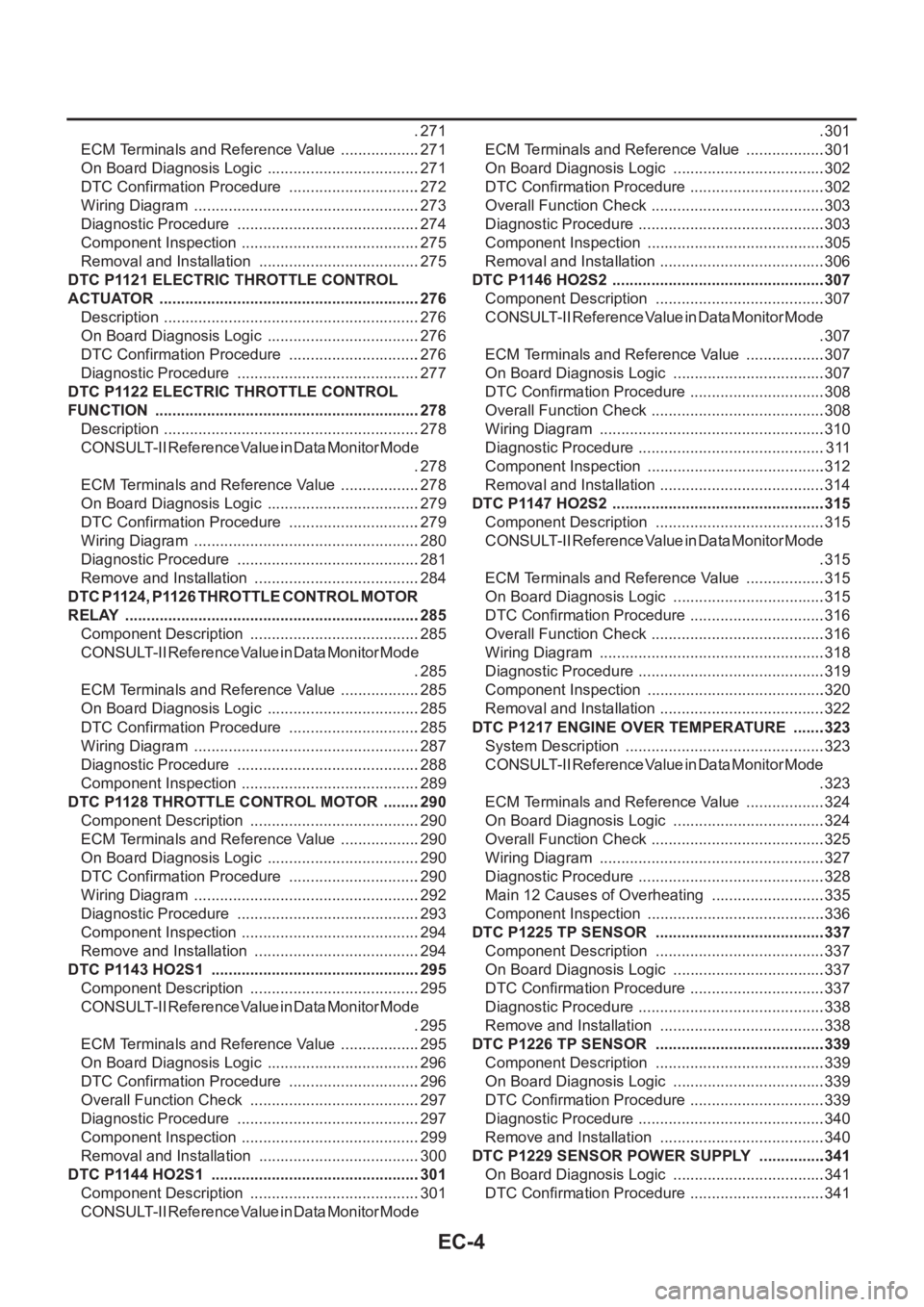
Main 12 Causes of Overheating ...........................335
Component Inspection ..........................................336
DTC P1225 TP SENSOR ........................................337
Component Description ........................................337
On Board Diagnosis Logic ....................................337
DTC Confirmation Procedure ................................337
Diagnostic Procedure ............................................338
Remove and Installation .......................................338
DTC P1226 TP SENSOR ........................................339
Component Description ........................................339
On Board Diagnosis Logic ....................................339
DTC Confirmation Procedure ................................339
Diagnostic Procedure ............................................340
Remove and Installation .......................................340
DTC P1229 SENSOR POWER SUPPLY ................341
On Board Diagnosis Logic ....................................341
DTC Confirmation Procedure ................................341
Page 358 of 3833

EC-8
Wiring Diagram .....................................................595
Diagnostic Procedure ...........................................596
Component Inspection ..........................................597
DTC P1128 THROTTLE CONTROL MOTOR .........598
Component Description ........................................598
ECM Terminals and Reference Value ...................598
On Board Diagnosis Logic ....................................598
DTC Confirmation Procedure ...............................598
Wiring Diagram .....................................................600
Diagnostic Procedure ...........................................601
Component Inspection ..........................................602
Remove and Installation .......................................602
DTC P1217 ENGINE OVER TEMPERATURE ........603
System Description ...............................................603
CONSULT-II Reference Value in Data Monitor Mode
.603
ECM Terminals and Reference Value ...................604
On Board Diagnosis Logic ....................................604
Overall Function Check ........................................605
Wiring Diagram .....................................................607
Diagnostic Procedure ...........................................608
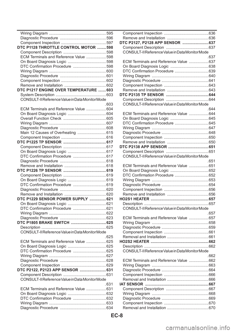
Main 12 Causes of Overheating ...........................615
Component Inspection ..........................................616
DTC P1225 TP SENSOR ........................................617
Component Description ........................................617
On Board Diagnosis Logic ....................................617
DTC Confirmation Procedure ...............................617
Diagnostic Procedure ...........................................618
Remove and Installation .......................................618
DTC P1226 TP SENSOR ........................................619
Component Description ........................................619
On Board Diagnosis Logic ....................................619
DTC Confirmation Procedure ...............................619
Diagnostic Procedure ...........................................620
Remove and Installation .......................................620
DTC P1229 SENSOR POWER SUPPLY ................621
On Board Diagnosis Logic ....................................621
DTC Confirmation Procedure ...............................621
Wiring Diagram .....................................................622
Diagnostic Procedure ...........................................623
DTC P1805 BRAKE SWITCH .................................625
Description ............................................................625
CONSULT-II Reference Value in Data Monitor Mode
.625
ECM Terminals and Reference Value ...................625
On Board Diagnosis Logic ....................................625
DTC Confirmation Procedure ...............................625
Wiring Diagram .....................................................627
Diagnostic Procedure ...........................................628
Component Inspection ..........................................629
DTC P2122, P2123 APP SENSOR .........................631
Component Description ........................................631
CONSULT-II Reference Value in Data Monitor Mode
.631
ECM Terminals and Reference Value ...................631
On Board Diagnosis Logic ....................................632
DTC Confirmation Procedure ...............................632
Wiring Diagram .....................................................633
Diagnostic Procedure ...........................................634Component Inspection ..........................................636
Remove and Installation .......................................636
DTC P2127, P2128 APP SENSOR .........................637
Component Description ........................................637
CONSULT-II Reference Value in Data Monitor Mode
.637
ECM Terminals and Reference Value ...................637
On Board Diagnosis Logic ....................................638
DTC Confirmation Procedure ................................639
Wiring Diagram .....................................................640
Diagnostic Procedure ............................................641
Component Inspection ..........................................643
Remove and Installation .......................................643
DTC P2135 TP SENSOR ........................................644
Component Description ........................................644
CONSULT-II Reference Value in Data Monitor Mode
.644
ECM Terminals and Reference Value ...................644
On Board Diagnosis Logic ....................................645
DTC Confirmation Procedure ................................645
Wiring Diagram .....................................................647
Diagnostic Procedure ............................................648
Component Inspection ..........................................650
Remove and Installation .......................................650
DTC P2138 APP SENSOR ......................................651
Component Description ........................................651
CONSULT-II Reference Value in Data Monitor Mode
.651
ECM Terminals and Reference Value ...................651
On Board Diagnosis Logic ....................................652
DTC Confirmation Procedure ................................652
Wiring Diagram .....................................................653
Diagnostic Procedure ............................................654
Component Inspection ..........................................656
Remove and Installation .......................................656
HO2S1 HEATER ......................................................657
Description ............................................................657
CONSULT-II Reference Value in Data Monitor Mode
.657
ECM Terminals and Reference Value ...................657
Wiring Diagram ....................................................
.658
Diagnostic Procedure ............................................659
Component Inspection ..........................................661
Removal and Installation .......................................661
HO2S2 HEATER ......................................................662
Description ............................................................662
CONSULT-II Reference Value in Data Monitor Mode
.662
ECM Terminals and Reference Value ...................662
Wiring Diagram .....................................................663
Diagnostic Procedure ............................................664
Component Inspection ..........................................666
Removal and Installation .......................................666
IAT SENSOR ...........................................................667
Component Description ........................................667
Wiring Diagram .....................................................668
Diagnostic Procedure ............................................669
Component Inspection ..........................................670
Removal and Installation .......................................670
Page 363 of 3833

EC-13
C
D
E
F
G
H
I
J
K
L
M
ECA On Board Diagnosis Logic ..................................1018
DTC Confirmation Procedure ..............................1018
Wiring Diagram ...................................................1020
Diagnostic Procedure ..........................................1021
Component Inspection ........................................1022
DTC P1143 HO2S1 ................................................1023
Component Description .......................................1023
CONSULT-II Reference Value in Data Monitor Mode
1023
ECM Terminals and Reference Value .................1023
On Board Diagnosis Logic ..................................1024
DTC Confirmation Procedure ..............................1024
Overall Function Check .......................................1025
Diagnostic Procedure ..........................................1025
Component Inspection ........................................1027
Removal and Installation .....................................1028
DTC P1144 HO2S1 ................................................1029
Component Description .......................................1029
CONSULT-II Reference Value in Data Monitor Mode
1029
ECM Terminals and Reference Value .................1029
On Board Diagnosis Logic ..................................1030
DTC Confirmation Procedure ..............................1030
Overall Function Check .......................................1031
Diagnostic Procedure ..........................................1031
Component Inspection ........................................1033
Removal and Installation .....................................1034
DTC P1146 HO2S2 ................................................1035
Component Description .......................................1035
CONSULT-II Reference Value in Data Monitor Mode
1035
ECM Terminals and Reference Value .................1035
On Board Diagnosis Logic ..................................1035
DTC Confirmation Procedure ..............................1036
Overall Function Check .......................................1037
Wiring Diagram ...................................................1038
Diagnostic Procedure ..........................................1039
Component Inspection ........................................1040
Removal and Installation .....................................1041
DTC P1147 HO2S2 ................................................1042
Component Description .......................................1042
CONSULT-II Reference Value in Data Monitor Mode
1042
ECM Terminals and Reference Value .................1042
On Board Diagnosis Logic ..................................1042
DTC Confirmation Procedure ..............................1043
Overall Function Check .......................................1044
Wiring Diagram ...................................................1045
Diagnostic Procedure ..........................................1046
Component Inspection ........................................1047
Removal and Installation .....................................1048
DTC P1212 ESP/TCS/ABS COMMUNICATION
LINE .......................................................................1049
Description ..........................................................1049
On Board Diagnosis Logic ..................................1049
DTC Confirmation Procedure ..............................1049
Diagnostic Procedure ..........................................1049
DTC P1217 ENGINE OVER TEMPERATURE ......1050
System Description .............................................1050CONSULT-II Reference Value in Data Monitor Mode
1050
ECM Terminals and Reference Value ..................1051
On Board Diagnosis Logic ...................................1051
Overall Function Check .......................................1052
Wiring Diagram ....................................................1054
Diagnostic Procedure ..........................................1055
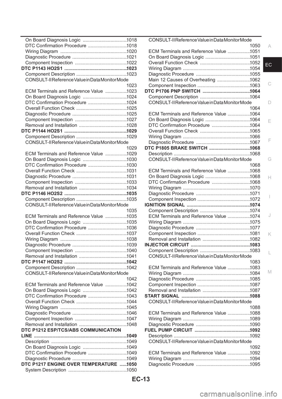
Main 12 Causes of Overheating ..........................1062
Component Inspection .........................................1063
DTC P1706 PNP SWITCH .....................................1064
Component Description .......................................1064
CONSULT-II Reference Value in Data Monitor Mode
1064
ECM Terminals and Reference Value ..................1064
On Board Diagnosis Logic ...................................1064
DTC Confirmation Procedure ..............................1064
Overall Function Check .......................................1065
Wiring Diagram ....................................................1066
Diagnostic Procedure ..........................................1067
DTC P1805 BRAKE SWITCH ................................1068
Description ...........................................................1068
CONSULT-II Reference Value in Data Monitor Mode
1068
ECM Terminals and Reference Value ..................1068
On Board Diagnosis Logic ...................................1068
DTC Confirmation Procedure ..............................1068
Wiring Diagram ....................................................1070
Diagnostic Procedure ..........................................1071
Component Inspection .........................................1072
IGNITION SIGNAL .................................................1074
Component Description .......................................1074
ECM Terminals and Reference Value ..................1074
Wiring Diagram ....................................................1075
Diagnostic Procedure ..........................................1077
Component Inspection .........................................1081
Removal and Installation .....................................1082
INJECTOR CIRCUIT ..............................................1083
Component Description .......................................1083
CONSULT-II Reference Value in Data Monitor Mode
1083
ECM Terminals and Reference Value ..................1083
Wiring Diagram ....................................................
1084
Diagnostic Procedure ..........................................1085
Component Inspection .........................................1087
Removal and Installation .....................................1087
START SIGNAL .....................................................1088
CONSULT-II Reference Value in Data Monitor Mode
1088
ECM Terminals and Reference Value ..................1088
Wiring Diagram ....................................................1089
Diagnostic Procedure ..........................................1090
FUEL PUMP CIRCUIT ...........................................1092
Description ...........................................................1092
CONSULT-II Reference Value in Data Monitor Mode
1092
ECM Terminals and Reference Value ..................1092
Wiring Diagram ....................................................1094
Diagnostic Procedure ..........................................1095