2001 NISSAN X-TRAIL Crank
[x] Cancel search: CrankPage 47 of 3833

TERMINOLOGY
GI-45
C
D
E
F
G
H
I
J
K
L
MB
GI
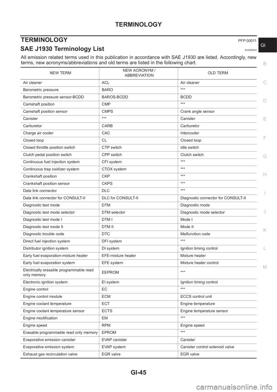
TERMINOLOGYPFP:00011
SAE J1930 Terminology List EAS000GH
All emission related terms used in this publication in accordance with SAE J1930 are listed. Accordingly, new
terms, new acronyms/abbreviations and old terms are listed in the following chart.
NEW TERMNEW ACRONYM /
ABBREVIATIONOLD TERM
Air cleaner ACL Air cleaner
Barometric pressure BARO ***
Barometric pressure sensor-BCDD BAROS-BCDD BCDD
Camshaft position CMP ***
Camshaft position sensor CMPS Crank angle sensor
Canister *** Canister
Carburetor CARB Carburetor
Charge air cooler CAC Intercooler
Closed loop CL Closed loop
Closed throttle position switch CTP switch Idle switch
Clutch pedal position switch CPP switch Clutch switch
Continuous fuel injection system CFI system ***
Continuous trap oxidizer system CTOX system ***
Crankshaft position CKP ***
Crankshaft position sensor CKPS ***
Data link connector DLC ***
Data link connector for CONSULT-II DLC for CONSULT-II Diagnostic connector for CONSULT-II
Diagnostic test mode DTM Diagnostic mode
Diagnostic test mode selector DTM selector Diagnostic mode selector
Diagnostic test mode I DTM I Mode I
Diagnostic test mode II DTM II Mode II
Diagnostic trouble code DTC Malfunction code
Direct fuel injection system DFI system ***
Distributor ignition system DI system Ignition timing control
Early fuel evaporation-mixture heater EFE-mixture heater Mixture heater
Early fuel evaporation system EFE system Mixture heater control
Electrically erasable programmable read
only memoryEEPROM ***
Electronic ignition system EI system Ignition timing control
Engine control EC ***
Engine control module ECM ECCS control unit
Engine coolant temperature ECT Engine temperature
Engine coolant temperature sensor ECTS Engine temperature sensor
Engine modification EM ***
Engine speed RPM Engine speed
Erasable programmable read only memory EPROM ***
Evaporative emission canister EVAP canister Canister
Evaporative emission system EVAP system Canister control solenoid valve
Exhaust gas recirculation valve EGR valve EGR valve
Page 49 of 3833

TERMINOLOGY
GI-47
C
D
E
F
G
H
I
J
K
L
MB
GI
Nonvolatile random access memory NVRAM ***
On board diagnostic system OBD system Self-diagnosis
Open loop OL Open loop
Oxidation catalyst OC Catalyst
Oxidation catalytic converter system OC system ***
Oxygen sensor O2S Exhaust gas sensor
Park position switch *** Park switch
Park/neutral position switch PNP switchPark/neutral switch
Inhibitor switch
Neutral position switch
Periodic trap oxidizer system PTOX system ***
Positive crankcase ventilation PCV Positive crankcase ventilation
Positive crankcase ventilation valve PCV valve PCV valve
Powertrain control module PCM ***
Programmable read only memory PROM ***
Pulsed secondary air injection control sole-
noid valvePAIRC solenoid valve AIV control solenoid valve
Pulsed secondary air injection system PAIR system Air induction valve (AIV) control
Pulsed secondary air injection valve PAIR valve Air induction valve
Random access memory RAM ***
Read only memory ROM ***
Scan tool ST ***
Secondary air injection pump AIR pump ***
Secondary air injection system AIR system ***
Sequential multiport fuel injection system SFI system Sequential fuel injection
Service reminder indicator SRI ***
Simultaneous multiport fuel injection sys-
tem*** Simultaneous fuel injection
Smoke puff limiter system SPL system ***
Supercharger SC ***
Supercharger bypass SCB ***
System readiness test SRT ***
Thermal vacuum valve TVV Thermal vacuum valve
Three way catalyst TWC Catalyst
Three way catalytic converter system TWC system ***
Three way + oxidation catalyst TWC + OC Catalyst
Three way + oxidation catalytic converter
systemTWC + OC system ***
Throttle body TBThrottle chamber
SPI body
Throttle body fuel injection system TBI system Fuel injection control
Throttle position TP Throttle position
Throttle position sensor TPS Throttle sensor
Throttle position switch TP switch Throttle switch
Torque converter clutch solenoid valve TCC solenoid valveLock-up cancel solenoid
Lock-up solenoid NEW TERMNEW ACRONYM /
ABBREVIATIONOLD TERM
Page 52 of 3833

EM-2
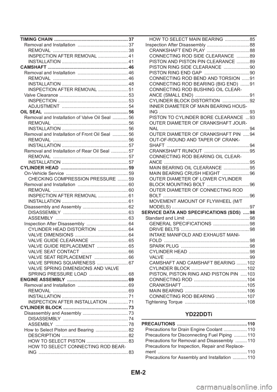
TIMING CHAIN .......................................................... 37
Removal and Installation ........................................ 37
REMOVAL ........................................................... 38
INSPECTION AFTER REMOVAL ........................ 41
INSTALLATION .................................................... 41
CAMSHAFT ............................................................... 46
Removal and Installation ........................................ 46
REMOVAL ........................................................... 46
INSTALLATION .................................................... 48
INSPECTION AFTER REMOVAL ........................ 51
Valve Clearance ...................................................... 53
INSPECTION ....................................................... 53
ADJUSTMENT .................................................... 54
OIL SEAL .................................................................. 56
Removal and Installation of Valve Oil Seal ............. 56
REMOVAL ........................................................... 56
INSTALLATION .................................................... 56
Removal and Installation of Front Oil Seal ............. 56
REMOVAL ........................................................... 56
INSTALLATION .................................................... 57
Removal and Installation of Rear Oil Seal .............. 57
REMOVAL ........................................................... 57
INSTALLATION .................................................... 57
CYLINDER HEAD .................................................. ... 59
On-Vehicle Service ................................................. 59
CHECKING COMPRESSION PRESSURE ......... 59
Removal and Installation ........................................ 60
REMOVAL ........................................................... 60
INSPECTION AFTER REMOVAL ........................ 61
INSTALLATION .................................................... 61
Disassembly and Assembly .................................... 62
DISASSEMBLY ................................................... 63
ASSEMBLY ......................................................... 63
Inspection After Disassembly ................................. 64
CYLINDER HEAD DISTORTION ........................ 64
VALVE DIMENSIONS .......................................... 64
VALVE GUIDE CLEARANCE .............................. 65
VALVE GUIDE REPLACEMENT ......................... 65
VALVE SEAT CONTACT ..................................... 66
VALVE SEAT REPLACEMENT ........................... 66
VALVE SPRING SQUARENESS ......................... 67
VALVE SPRING DIMENSIONS AND VALVE
SPRING PRESSURE LOAD ............................... 68
ENGINE ASSEMBLY ................................................ 69
Removal and Installation ........................................ 69
REMOVAL .......................................................
.... 69
INSTALLATION .................................................... 71
INSPECTION AFTER INSTALLATION ................ 71
CYLINDER BLOCK ................................................... 73
Disassembly and Assembly .................................... 73
DISASSEMBLY ................................................... 74
ASSEMBLY ......................................................... 78
How to Select Piston and Bearing .......................... 82
DESCRIPTION .................................................... 82
HOW TO SELECT PISTON ................................. 83
HOW TO SELECT CONNECTING ROD BEAR-
ING ...................................................................... 83HOW TO SELECT MAIN BEARING .................... 85
Inspection After Disassembly .................................. 88
CRANKSHAFT END PLAY .................................. 88
CONNECTING ROD SIDE CLEARANCE ........... 89
PISTON AND PISTON PIN CLEARANCE ........... 89
PISTON RING SIDE CLEARANCE ..................... 90
PISTON RING END GAP .................................... 90
CONNECTING ROD BEND AND TORSION ....... 91
CONNECTING ROD BEARING (BIG END) ........ 91
CONNECTING ROD BUSHING OIL CLEAR-
ANCE (SMALL END) ........................................... 91
CYLINDER BLOCK DISTORTION ...................... 92
INNER DIAMETER OF MAIN BEARING HOUS-
ING ....................................................................... 93
PISTON TO CYLINDER BORE CLEARANCE .... 93
OUTER DIAMETER OF CRANKSHAFT JOUR-
NAL ...................................................................... 94
OUTER DIAMETER OF CRANKSHAFT PIN ...... 94
OUT-OF-ROUND AND TAPER OF CRANK-
SHAFT ................................................................. 94
CRANKSHAFT RUNOUT .................................... 95
CONNECTING ROD BEARING OIL CLEAR-
ANCE ................................................................... 95
MAIN BEARING OIL CLEARANCE ..................... 95
MAIN BEARING CRUSH HEIGHT ...................... 96
OUTER DIAMETER OF LOWER CYLINDER
BLOCK MOUNTING BOLT .................................. 96
OUTER DIAMETER OF CONNECTING ROD
BOLT .................................................................... 96
MOVEMENT AMOUNT OF FLYWHEEL (M/T
MODELS) ............................................................. 97
SERVICE DATA AND SPECIFICATIONS (SDS) ...... 98
Standard and Limit .................................................. 98
GENERAL SPECIFICATIONS ............................. 98
DRIVE BELTS ...................................................... 98
INTAKE MANIFOLD AND EXHAUST MANI-
FOLD ................................................................... 98
SPARK PLUG ...................................................... 98
CYLINDER HEAD ................................................ 98
VALVE .................................................................. 99
CAMSHAFT AND CAMSHAFT BEARING .........102
CYLINDER BLOCK ............................................102
PISTON, PISTON RING AND PISTON PIN .....
.103
CONNECTING ROD ..........................................104
CRANKSHAFT ...................................................105
MAIN BEARING .................................................106
CONNECTING ROD BEARING .........................107
Tightening Torque .................................................108
YD22DDTi
PRECAUTIONS .......................................................110
Precautions for Drain Engine Coolant ...................110
Precautions for Disconnecting Fuel Piping ...........110
Precautions for Removal and Disassembly ..........110
Precautions for Inspection, Repair and Replace-
ment ......................................................................110
Precautions for Assembly and Installation ............110
Page 54 of 3833

EM-4
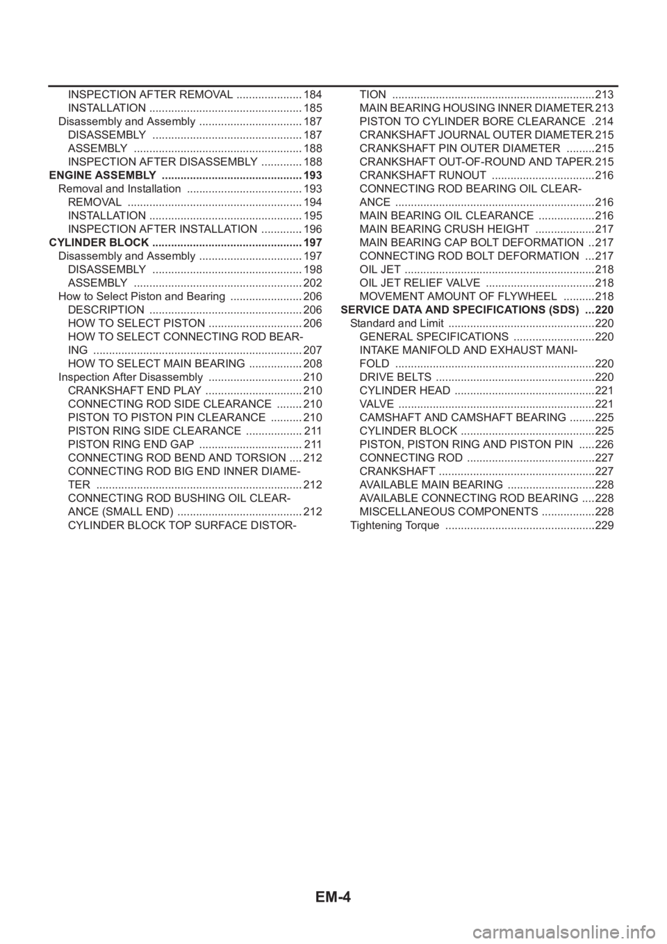
INSPECTION AFTER REMOVAL ......................184
INSTALLATION ..................................................185
Disassembly and Assembly ..................................187
DISASSEMBLY .................................................187
ASSEMBLY .......................................................188
INSPECTION AFTER DISASSEMBLY ..............188
ENGINE ASSEMBLY ..............................................193
Removal and Installation ......................................193
REMOVAL .........................................................194
INSTALLATION ..................................................195
INSPECTION AFTER INSTALLATION ..............196
CYLINDER BLOCK .................................................197
Disassembly and Assembly ..................................197
DISASSEMBLY .................................................198
ASSEMBLY .......................................................202
How to Select Piston and Bearing ........................206
DESCRIPTION ..................................................206
HOW TO SELECT PISTON ...............................206
HOW TO SELECT CONNECTING ROD BEAR-
ING ....................................................................207
HOW TO SELECT MAIN BEARING ..................208
Inspection After Disassembly ...............................210
CRANKSHAFT END PLAY ................................210
CONNECTING ROD SIDE CLEARANCE .........210
PISTON TO PISTON PIN CLEARANCE ...........210
PISTON RING SIDE CLEARANCE ...................211
PISTON RING END GAP ..................................211
CONNECTING ROD BEND AND TORSION .....212
CONNECTING ROD BIG END INNER DIAME-
TER ...................................................................212
CONNECTING ROD BUSHING OIL CLEAR-
ANCE (SMALL END) .........................................212
CYLINDER BLOCK TOP SURFACE DISTOR-TION ..................................................................213
MAIN BEARING HOUSING INNER DIAMETER .213
PISTON TO CYLINDER BORE CLEARANCE ..214
CRANKSHAFT JOURNAL OUTER DIAMETER .215
CRANKSHAFT PIN OUTER DIAMETER ..........215
CRANKSHAFT OUT-OF-ROUND AND TAPER .215
CRANKSHAFT RUNOUT ..................................216
CONNECTING ROD BEARING OIL CLEAR-
ANCE .................................................................216
MAIN BEARING OIL CLEARANCE ...................216
MAIN BEARING CRUSH HEIGHT ....................217
MAIN BEARING CAP BOLT DEFORMATION ...217
CONNECTING ROD BOLT DEFORMATION ....217
OIL JET ..............................................................218
OIL JET RELIEF VALVE ....................................218
MOVEMENT AMOUNT OF FLYWHEEL ...........218
SERVICE DATA AND SPECIFICATIONS (SDS) ....220
Standard and Limit ...............................................
.220
GENERAL SPECIFICATIONS ...........................220
INTAKE MANIFOLD AND EXHAUST MANI-
FOLD .................................................................220
DRIVE BELTS ....................................................220
CYLINDER HEAD ..............................................221
VALVE ................................................................221
CAMSHAFT AND CAMSHAFT BEARING .........225
CYLINDER BLOCK ............................................225
PISTON, PISTON RING AND PISTON PIN ......226
CONNECTING ROD ..........................................227
CRANKSHAFT ...................................................227
AVAILABLE MAIN BEARING .............................228
AVAILABLE CONNECTING ROD BEARING .....228
MISCELLANEOUS COMPONENTS ..................228
Tightening Torque .................................................229
Page 55 of 3833
![NISSAN X-TRAIL 2001 Service Repair Manual PRECAUTIONS
EM-5
[QR]
C
D
E
F
G
H
I
J
K
L
MA
EM
[QR]PRECAUTIONSPFP:00001
Precautions for Drain Engine CoolantEBS00KN0
Drain engine coolant when engine is cooled.
Precautions for Disconnecting Fuel Pip NISSAN X-TRAIL 2001 Service Repair Manual PRECAUTIONS
EM-5
[QR]
C
D
E
F
G
H
I
J
K
L
MA
EM
[QR]PRECAUTIONSPFP:00001
Precautions for Drain Engine CoolantEBS00KN0
Drain engine coolant when engine is cooled.
Precautions for Disconnecting Fuel Pip](/manual-img/5/57405/w960_57405-54.png)
PRECAUTIONS
EM-5
[QR]
C
D
E
F
G
H
I
J
K
L
MA
EM
[QR]PRECAUTIONSPFP:00001
Precautions for Drain Engine CoolantEBS00KN0
Drain engine coolant when engine is cooled.
Precautions for Disconnecting Fuel PipingEBS00KN1
●Before starting work, make sure no fire or spark producing items are in the work area.
●Release fuel pressure before disassembly.
●After disconnecting pipes, plug openings to stop fuel leakage.
Precautions for Removal and DisassemblyEBS00KN2
●When instructed to use special service tools, use the specified tools. Always be careful to work safely,
avoid forceful or uninstructed operations.
●Exercise maximum care to avoid damage to mating or sliding surfaces.
●Cover openings of engine system with tape or the equivalent, if necessary, to seal out foreign materials.
●Mark and arrange disassembly parts in an organized way for easy troubleshooting and re-assembly.
●When loosening nuts and bolts, as a basic rule, start with the one furthest outside, then the one diagonally
opposite, and so on. If the order of loosening is specified, do exactly as specified.
Precautions for Inspection, Repair and ReplacementEBS00KN3
Before repairing or replacing, thoroughly inspect parts. Inspect new replacement parts in the same way, and
replace if necessary.
Precautions for Assembly and InstallationEBS00MRZ
●Use torque wrench to tighten bolts or nuts to specification.
●When tightening nuts and bolts, as a basic rule, equally tighten in several different steps starting with the
ones in center, then ones on inside and outside diagonally in this order. If the order of tightening is speci-
fied, do exactly as specified.
●Replace with new gasket, packing, oil seal or O-ring.
●Thoroughly wash, clean, and air-blow each part. Carefully check oil or coolant passages for any restriction
and blockage.
●Avoid damaging sliding or mating surfaces. Completely remove foreign materials such as cloth lint or dust.
Before assembly, oil sliding surfaces well.
●Release air within route when refilling after draining coolant.
●Before starting engine, apply fuel pressure to fuel lines with turning ignition switch ON (with engine
stopped). Then mark sure that there are no leaks at fuel line connections.
●After repairing, start engine and increase engine speed to check coolant, fuel, oil, and exhaust systems
for leakage.
Parts Requiring Angular TighteningEBS00KN5
●Use an angle wrench for the final tightening of the following engine parts.
–Cylinder head bolts
–Lower cylinder block bolts
–Connecting rod cap bolts
–Crankshaft pulley bolt (No angle wrench is required as the bolt flange is provided with notches for angular
tightening)
●Do not use a torque value for final tightening.
●The torque value for these parts are for a preliminary step.
●Ensure thread and seat surfaces are clean and coated with engine oil.
Page 58 of 3833
![NISSAN X-TRAIL 2001 Service Repair Manual EM-8
[QR]
PREPARATION
Commercial Service Tools
EBS00L7O
KV10107902
Valve oil seal pullerRemoving valve oil seal
KV10115600
Valve oil seal driftInstalling valve oil seal
Use side A.
a: 20 (0.79) dia. NISSAN X-TRAIL 2001 Service Repair Manual EM-8
[QR]
PREPARATION
Commercial Service Tools
EBS00L7O
KV10107902
Valve oil seal pullerRemoving valve oil seal
KV10115600
Valve oil seal driftInstalling valve oil seal
Use side A.
a: 20 (0.79) dia.](/manual-img/5/57405/w960_57405-57.png)
EM-8
[QR]
PREPARATION
Commercial Service Tools
EBS00L7O
KV10107902
Valve oil seal pullerRemoving valve oil seal
KV10115600
Valve oil seal driftInstalling valve oil seal
Use side A.
a: 20 (0.79) dia. d: 8 (0.31) dia.
b: 13 (0.51) dia. e: 10.7 (0.421) dia.
c: 10.3 (0.406) dia. f: 5 (0.20) dia.
Unit: mm (in)
EM03470000
Piston ring compressorInstalling piston assembly into cylinder bore
ST16610001
Pilot bushing pullerRemoving crankshaft pilot bushing
WS39930000
Tube presserPressing the tube of liquid gasket Tool number
Tool nameDescription
S-NT011
S-NT603
S-NT044
S-NT045
S-NT052
Tool nameDescription
Quick connector release Removing fuel tube quick connectors in
engine room
(Available in SEC. 164 of PARTS CATALOG:
Part No. 16441 6N210)
Pulley holderCrankshaft pulley removing and installing
a: 68 mm (2.68 in)
b: 8 mm (0.31 in)
PBIC0198E
NT628
Page 59 of 3833
![NISSAN X-TRAIL 2001 Service Repair Manual PREPARATION
EM-9
[QR]
C
D
E
F
G
H
I
J
K
L
MA
EM
Crank pullerCrankshaft pulley removing
Spark plug wrench Removing and installing spark plug
Valve seat cutter set Finishing valve seat dimensions
Piston NISSAN X-TRAIL 2001 Service Repair Manual PREPARATION
EM-9
[QR]
C
D
E
F
G
H
I
J
K
L
MA
EM
Crank pullerCrankshaft pulley removing
Spark plug wrench Removing and installing spark plug
Valve seat cutter set Finishing valve seat dimensions
Piston](/manual-img/5/57405/w960_57405-58.png)
PREPARATION
EM-9
[QR]
C
D
E
F
G
H
I
J
K
L
MA
EM
Crank pullerCrankshaft pulley removing
Spark plug wrench Removing and installing spark plug
Valve seat cutter set Finishing valve seat dimensions
Piston ring expander Removing and installing piston ring
Valve guide drift Removing and installing valve guide
Intake & Exhaust:
a: 9.5 mm (0.374 in) dia.
b: 5.5 mm (0.217 in) dia.
Valve guide reamer 1: Reaming valve guide inner hole
2: Reaming hole for oversize valve guide
Intake & Exhaust:
d1: 6.0 mm (0.236 in) dia.
d2: 10.2 mm (0.402 in) dia. To o l n a m eDescription
ZZA0010D
S-NT047
S-NT048
S-NT030
S-NT015
S-NT016
Page 61 of 3833
![NISSAN X-TRAIL 2001 Service Repair Manual NOISE, VIBRATION, AND HARSHNESS (NVH) TROUBLESHOOTING
EM-11
[QR]
C
D
E
F
G
H
I
J
K
L
MA
EM
Use the Chart Below to Help You Find the Cause of the Symptom.EBS00L7Q
1. Locate the area where noise occurs. NISSAN X-TRAIL 2001 Service Repair Manual NOISE, VIBRATION, AND HARSHNESS (NVH) TROUBLESHOOTING
EM-11
[QR]
C
D
E
F
G
H
I
J
K
L
MA
EM
Use the Chart Below to Help You Find the Cause of the Symptom.EBS00L7Q
1. Locate the area where noise occurs.](/manual-img/5/57405/w960_57405-60.png)
NOISE, VIBRATION, AND HARSHNESS (NVH) TROUBLESHOOTING
EM-11
[QR]
C
D
E
F
G
H
I
J
K
L
MA
EM
Use the Chart Below to Help You Find the Cause of the Symptom.EBS00L7Q
1. Locate the area where noise occurs.
2. Confirm the type of noise.
3. Specify the operating condition of engine.
4. Check specified noise source.
If necessary, repair or replace these parts.
A: Closely related B: Related C: Sometimes related —: Not relatedLocation
of noiseType of
noiseOperating condition of engine
Source of
noiseCheck itemRefer-
ence page Before
warm-
upAfter
warm-
upWhen
start-
ingWhen
idlingWhen
racingWhile
driving
Top of
engine
Rocker
cover
Cylinder
headTicking or
clickingCA—AB—Tappet
noiseValve clearanceEM-53
Rattle C A — A B CCamshaft
bearing
noiseCamshaft journal clear-
ance
Camshaft runoutEM-51EM-51
Crank-
shaft pul-
ley
Cylinder
block
(Side of
engine)
Oil panSlap or
knock—A—BB—Piston pin
noisePiston and piston pin
clearance
Connecting rod bush-
ing oil clearance (Small
end)EM-89
EM-91
Slap or
rapA ——BBAPiston
slap noisePiston to cylinder bore
clearance
Piston ring side clear-
ance
Piston ring end gap
Connecting rod bend
and torsionEM-94EM-90
EM-90
EM-91
Knock A B C B B BConnect-
ing rod
bearing
noiseConnecting rod bush-
ing oil clearance (Small
end)
Connecting rod bear-
ing clearance (Big end)EM-91EM-91
Knock A B — A B CMain
bearing
noiseMain bearing oil clear-
ance
Crankshaft runoutEM-95EM-95
Front of
engine
Timing
chain
coverTapping or
tickingA A —BBBTiming
chain and
chain ten-
sioner
noiseTiming chain cracks
and wear
Timing chain tensioner
operationEM-37
Front of
engineSqueak-
ing or fizz-
ingAB—B—CDrive belts
(Sticking
or slip-
ping)Drive belts deflection
EM-12
CreakingA B ABABDrive belts
(Slipping)Idler pulley bearing
operation
Squall
CreakA B —BABWater
pump
noiseWater pump operationCO-18,
"WATER
PUMP"