2001 NISSAN X-TRAIL tire pressure
[x] Cancel search: tire pressurePage 2108 of 3833
AT-30
OVERALL SYSTEM
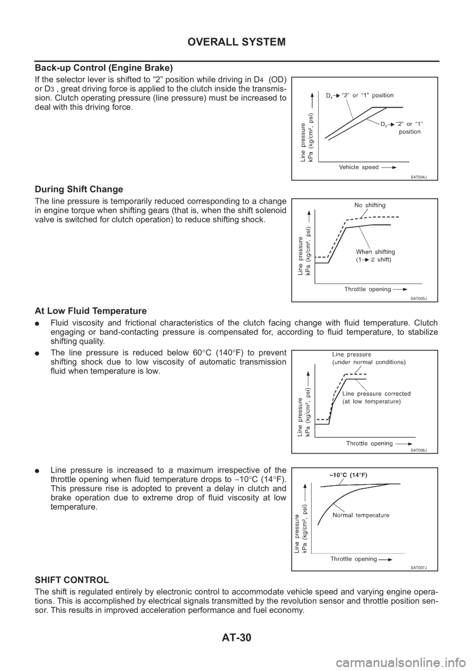
Back-up Control (Engine Brake)
If the selector lever is shifted to “2” position while driving in D4 (OD)
or D
3 , great driving force is applied to the clutch inside the transmis-
sion. Clutch operating pressure (line pressure) must be increased to
deal with this driving force.
During Shift Change
The line pressure is temporarily reduced corresponding to a change
in engine torque when shifting gears (that is, when the shift solenoid
valve is switched for clutch operation) to reduce shifting shock.
At Low Fluid Temperature
●Fluid viscosity and frictional characteristics of the clutch facing change with fluid temperature. Clutch
engaging or band-contacting pressure is compensated for, according to fluid temperature, to stabilize
shifting quality.
●The line pressure is reduced below 60°C (140°F) to prevent
shifting shock due to low viscosity of automatic transmission
fluid when temperature is low.
●Line pressure is increased to a maximum irrespective of the
throttle opening when fluid temperature drops to −10°C (14°F).
This pressure rise is adopted to prevent a delay in clutch and
brake operation due to extreme drop of fluid viscosity at low
temperature.
SHIFT CONTROL
The shift is regulated entirely by electronic control to accommodate vehicle speed and varying engine opera-
tions. This is accomplished by electrical signals transmitted by the revolution sensor and throttle position sen-
sor. This results in improved acceleration performance and fuel economy.
SAT004J
SAT005J
SAT006J
SAT007J
Page 2641 of 3833
ALL MODE 4X4 SYSTEM
TF-31
C
E
F
G
H
I
J
K
L
MA
B
TF
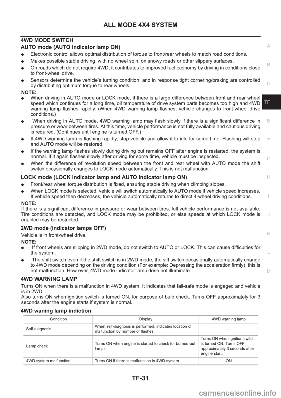
4WD MODE SWITCH
AUTO mode (AUTO indicator lamp ON)
●Electronic control allows optimal distribution of torque to front/rear wheels to match road conditions.
●Makes possible stable driving, with no wheel spin, on snowy roads or other slippery surfaces.
●On roads which do not require 4WD, it contributes to improved fuel economy by driving in conditions close
to front-wheel drive.
●Sensors determine the vehicle's turning condition, and in response tight cornering/braking are controlled
by distributing optimum torque to rear wheels.
NOTE:
●When driving in AUTO mode or LOCK mode, if there is a large difference between front and rear wheel
speed which continues for a long time, oil temperature of drive system parts becomes too high and 4WD
warning lamp flashes rapidly. (When 4WD warning lamp flashes, vehicle changes to front-wheel drive
conditions.)
● When driving in AUTO mode, 4WD warning lamp may flash slowly if there is a significant difference in
pressure or wear between tires. At this time, vehicle performance is not fully available and cautious driving
is required. (Continues until engine is turned OFF.)
●If 4WD warning lamp is flashing rapidly, stop vehicle and allow it to idle for some time. Flashing will stop
and AUTO mode will be restored.
●If the warning lamp flashes slowly during driving but remains OFF after engine is restarted, the system is
normal. If it again flashes slowly after driving for some time, vehicle must be inspected.
●When the difference of revolution speed between the front and rear wheel with AUTO mode the shift
switch occasionally changes to LOCK mode automatically. This is not malfunction.
LOCK mode (LOCK indicator lamp and AUTO indicator lamp ON)
●Front/rear wheel torque distribution is fixed, ensuring stable driving when climbing slopes.
●When LOCK mode is selected, vehicle will switch automatically to AUTO mode if vehicle speed increases.
If vehicle speed then decreases, the vehicle automatically returns to direct 4-wheel driving conditions.
NOTE:
If there is a significant difference in pressure or wear between tires, full vehicle performance is not available.
Tire conditions are detected, and LOCK mode may be prohibited, or else speeds at which LOCK mode is
enabled may be restricted.
2WD mode (indicator lamps OFF)
Vehicle is in front-wheel drive.
NOTE:
● If front wheels are slipping in 2WD mode, do not switch to AUTO or LOCK. This can cause difficulties for
the system.
● The shift switch even if the shift switch is in 2WD mode, the sift switch occasionally automatically change
to 4WD mode depending on the driving condition (For example; Depressing the acceleration firmly). this is
not malfunction. How ever, 4WD mode indicator lamp dose not illuminate.
4WD WARNING LAMP
Turns ON when there is a malfunction in 4WD system. It indicates that fail-safe mode is engaged and vehicle
is in 2WD.
Also turns ON when ignition switch is turned ON, for purpose of bulb check. Turns OFF approximately for 3
seconds after the engine starts if system is normal.
4WD waning lamp indiction
Condition Display 4WD warning lamp
Self-diagnosisWhen self-diagnosis is performed, indicates location of
malfunction by number of flashes.-
Lamp checkTurns ON when engine is started to check for burned-out
lamps.Turns ON when ignition switch
is turned ON. Turns OFF
approximately 3 seconds after
engine start.
4WD system malfunction Turns ON if there is malfunction in 4WD system. ON
Page 2654 of 3833
TF-44
TROUBLE DIAGNOSIS
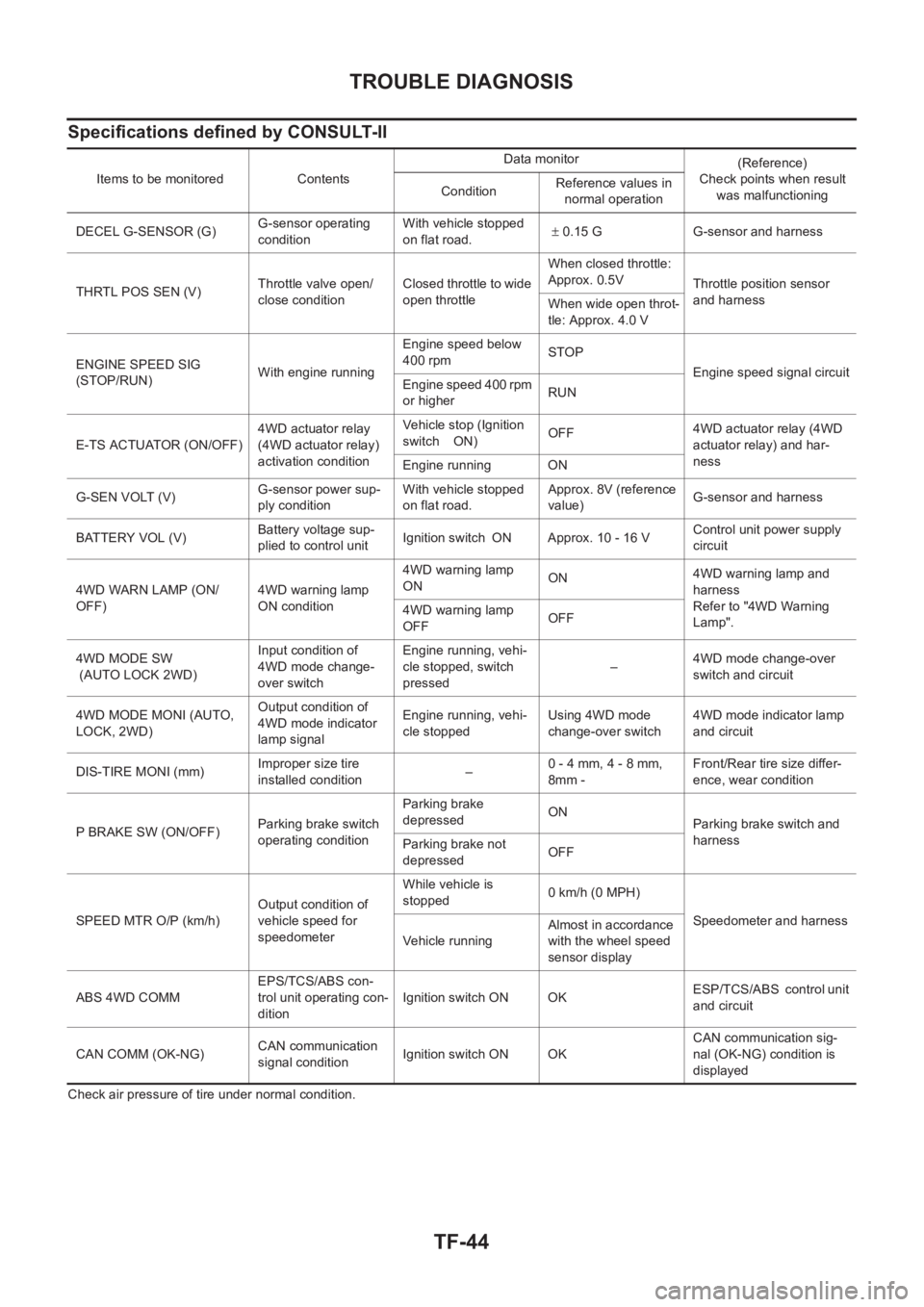
Specifications defined by CONSULT-II
Check air pressure of tire under normal condition.Items to be monitored ContentsData monitor
(Reference)
Check points when result
was malfunctioning ConditionReference values in
normal operation
DECEL G-SENSOR (G)G-sensor operating
conditionWith vehicle stopped
on flat road.± 0.15 G G-sensor and harness
THRTL POS SEN (V)Throttle valve open/
close conditionClosed throttle to wide
open throttleWhen closed throttle:
Approx. 0.5V
Throttle position sensor
and harness
When wide open throt-
tle: Approx. 4.0 V
ENGINE SPEED SIG
(STOP/RUN)With engine runningEngine speed below
400 rpmSTOP
Engine speed signal circuit
Engine speed 400 rpm
or higherRUN
E-TS ACTUATOR (ON/OFF)4WD actuator relay
(4WD actuator relay)
activation conditionVehicle stop (Ignition
switch ON)OFF4WD actuator relay (4WD
actuator relay) and har-
ness
Engine running ON
G-SEN VOLT (V)G-sensor power sup-
ply conditionWith vehicle stopped
on flat road.Approx. 8V (reference
value)G-sensor and harness
BATTERY VOL (V)Battery voltage sup-
plied to control unitIgnition switch ON Approx. 10 - 16 VControl unit power supply
circuit
4WD WARN LAMP (ON/
OFF)4WD warning lamp
ON condition4WD warning lamp
ONON4WD warning lamp and
harness
Refer to "4WD Warning
Lamp". 4WD warning lamp
OFFOFF
4WD MODE SW
(AUTO LOCK 2WD)Input condition of
4WD mode change-
over switchEngine running, vehi-
cle stopped, switch
pressed–4WD mode change-over
switch and circuit
4WD MODE MONI (AUTO,
LOCK, 2WD)Output condition of
4WD mode indicator
lamp signalEngine running, vehi-
cle stoppedUsing 4WD mode
change-over switch4WD mode indicator lamp
and circuit
DIS-TIRE MONI (mm)Improper size tire
installed condition
–0 - 4 mm, 4 - 8 mm,
8mm -Front/Rear tire size differ-
ence, wear condition
P BRAKE SW (ON/OFF)Parking brake switch
operating conditionParking brake
depressedON
Parking brake switch and
harness
Parking brake not
depressedOFF
SPEED MTR O/P (km/h)Output condition of
vehicle speed for
speedometerWhile vehicle is
stopped 0 km/h (0 MPH)
Speedometer and harness
Ve h i c le r u n n in gAlmost in accordance
with the wheel speed
sensor display
ABS 4WD COMMEPS/TCS/ABS con-
trol unit operating con-
ditionIgnition switch ON OKESP/TCS/ABS control unit
and circuit
CAN COMM (OK-NG)CAN communication
signal conditionIgnition switch ON OKCAN communication sig-
nal (OK-NG) condition is
displayed
Page 2668 of 3833
TF-58
TROUBLE DIAGNOSIS
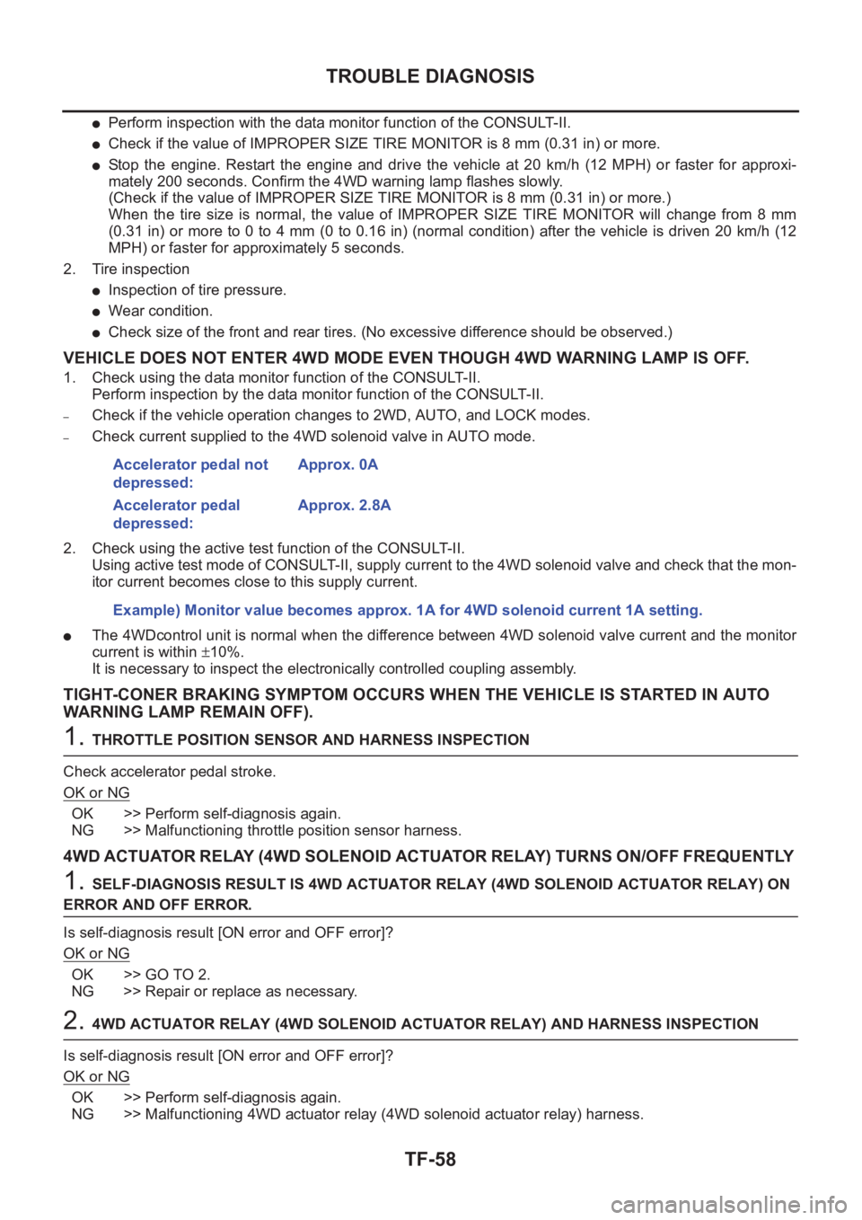
●Perform inspection with the data monitor function of the CONSULT- I I .
●Check if the value of IMPROPER SIZE TIRE MONITOR is 8 mm (0.31 in) or more.
●Stop the engine. Restart the engine and drive the vehicle at 20 km/h (12 MPH) or faster for approxi-
mately 200 seconds. Confirm the 4WD warning lamp flashes slowly.
(Check if the value of IMPROPER SIZE TIRE MONITOR is 8 mm (0.31 in) or more.)
When the tire size is normal, the value of IMPROPER SIZE TIRE MONITOR will change from 8 mm
(0.31 in) or more to 0 to 4 mm (0 to 0.16 in) (normal condition) after the vehicle is driven 20 km/h (12
MPH) or faster for approximately 5 seconds.
2. Tire inspection
●Inspection of tire pressure.
●Wear condition.
●Check size of the front and rear tires. (No excessive difference should be observed.)
VEHICLE DOES NOT ENTER 4WD MODE EVEN THOUGH 4WD WARNING LAMP IS OFF.
1. Check using the data monitor function of the CONSULT-II.
Perform inspection by the data monitor function of the CONSULT-II.
–Check if the vehicle operation changes to 2WD, AUTO, and LOCK modes.
–Check current supplied to the 4WD solenoid valve in AUTO mode.
2. Check using the active test function of the CONSULT-II.
Using active test mode of CONSULT-II, supply current to the 4WD solenoid valve and check that the mon-
itor current becomes close to this supply current.
●The 4WDcontrol unit is normal when the difference between 4WD solenoid valve current and the monitor
current is within ±10%.
It is necessary to inspect the electronically controlled coupling assembly.
TIGHT-CONER BRAKING SYMPTOM OCCURS WHEN THE VEHICLE IS STARTED IN AUTO
WARNING LAMP REMAIN OFF).
1. THROTTLE POSITION SENSOR AND HARNESS INSPECTION
Check accelerator pedal stroke.
OK or NG
OK >> Perform self-diagnosis again.
NG >> Malfunctioning throttle position sensor harness.
4WD ACTUATOR RELAY (4WD SOLENOID ACTUATOR RELAY) TURNS ON/OFF FREQUENTLY
1. SELF-DIAGNOSIS RESULT IS 4WD ACTUATOR RELAY (4WD SOLENOID ACTUATOR RELAY) ON
ERROR AND OFF ERROR.
Is self-diagnosis result [ON error and OFF error]?
OK or NG
OK >> GO TO 2.
NG >> Repair or replace as necessary.
2. 4WD ACTUATOR RELAY (4WD SOLENOID ACTUATOR RELAY) AND HARNESS INSPECTION
Is self-diagnosis result [ON error and OFF error]?
OK or NG
OK >> Perform self-diagnosis again.
NG >> Malfunctioning 4WD actuator relay (4WD solenoid actuator relay) harness. Accelerator pedal not
depressed:Approx. 0A
Accelerator pedal
depressed:Approx. 2.8A
Example) Monitor value becomes approx. 1A for 4WD solenoid current 1A setting.
Page 2712 of 3833
FSU-6
FRONT SUSPENSION ASSEMBLY
On-Vehicle Inspection and Service
EES00072
LOOSENESS, BACKLASH AND DAMAGE OF MOUNTING PARTS AND CONNECTIONS
Lift vehicle and inspect the following:
●Check mounting point of each component for looseness, backlash and damage.
●Check lower ball joint end play.
1. Attach a dial gauge so that the contact rests on the brake caliper.
2. Set front wheels in a straight-ahead position. Do not depress brake pedal.
3. Measure axial endplay by placing an iron pry bar or something similar between transverse link and steer-
ing knuckle.
CAUTION:
Be careful not to damage ball joint boot.
4. If axial endplay is outside the standard, remove transverse link and check lower ball joint.
Wheel AlignmentEES00073
DESCRIPTION
●Measure wheel alignment under unladen conditions. “Unladen conditions” means that fuel, coolant, and
lubricant are full. However, spare tire, jack, and hand tools should be unloaded.
PRELIMINARY INSPECTION
1. Check the tires for improper air pressure and wear.
2. Check road wheels for runout.
3. Check wheel bearing axial endplay.
4. Check lower ball joint axial endplay.
5. Check strut operation.
6. Check each mounting point of axle and suspension for looseness and deformation.
7. Check each link and arm for cracks, deformation, and other damage.
8. Check the vehicle posture.
INSPECTION OF CAMBER, CASTER, AND KINGPIN INCLINATION ANGLES
● Camber, caster, and kingpin inclination angles cannot be adjusted.
●Before inspection, mount front wheels onto turning radius gauge. Mount rear wheels onto a stand that has
same height so the vehicle will remain horizontal.
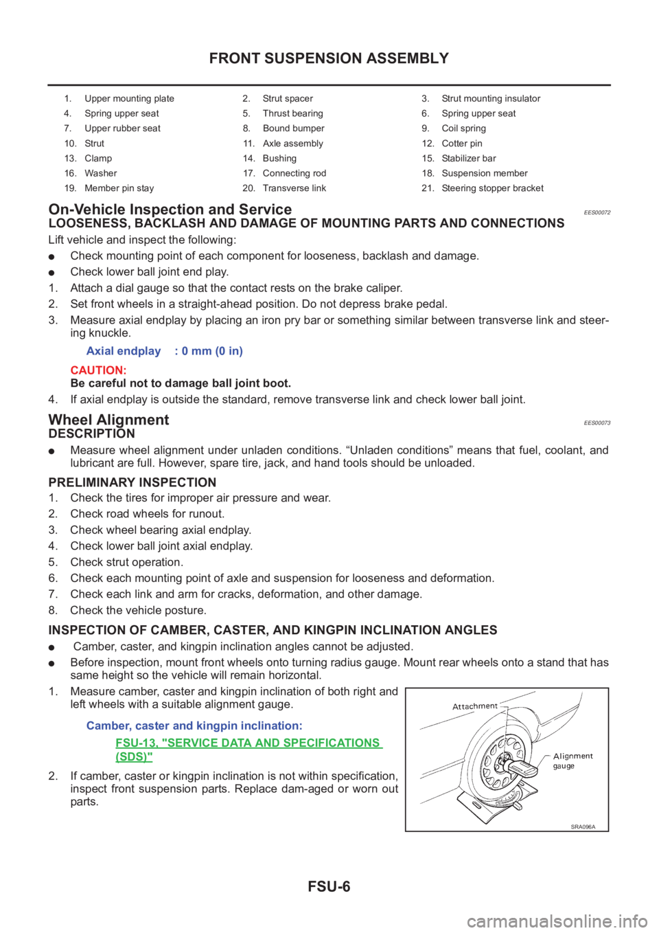
1. Measure camber, caster and kingpin inclination of both right and
left wheels with a suitable alignment gauge.
2. If camber, caster or kingpin inclination is not within specification,
inspect front suspension parts. Replace dam-aged or worn out
parts.
1. Upper mounting plate 2. Strut spacer 3. Strut mounting insulator
4. Spring upper seat 5. Thrust bearing 6. Spring upper seat
7. Upper rubber seat 8. Bound bumper 9. Coil spring
10. Strut 11. Axle assembly 12. Cotter pin
13. Clamp 14. Bushing 15. Stabilizer bar
16. Washer 17. Connecting rod 18. Suspension member
19. Member pin stay 20. Transverse link 21. Steering stopper bracket
Axial endplay : 0 mm (0 in)
Camber, caster and kingpin inclination:
FSU-13, "
SERVICE DATA AND SPECIFICATIONS
(SDS)"
SRA096A
Page 2726 of 3833
RSU-6
REAR SUSPENSION ASSEMBLY
On-Vehicle Inspection and Service
EES0007F
Check axle and suspension parts for excessive play, wear, and damage.
●Move rear wheels (RH/LH) to check abnormal free play.
●Retighten all nuts and bolts to the specified torque.
●Check strut for oil leakage and damage.
Wheel AlignmentEES0007G
DESCRIPTION
●Measure wheel alignment under unladen conditions. “Unladen conditions” means that fuel, coolant, and
lubricant are full. However, spare tire, jack, and hand tools should be unloaded.
PRELIMINARY INSPECTION
1. Check the tires for improper air pressure and wear.
2. Check road wheels for runout.
3. Check wheel bearing axial endplay.
4. Check strut operation.
5. Check each mounting point of axle and suspension for looseness and deformation.
6. Check each link and arm for cracks, deformation, and other damage.
7. Check the vehicle posture.
CAMBER
Camber is preset at factory and cannot be adjusted.
●If the camber is not within specification, inspect and replace any damaged or worn rear suspension parts.
TOE-IN
Measure toe-in using the following procedure.
●Always perform following procedure on a flat surface.
●Make sure that no person is in front of the vehicle before push-
ing it.
1. Bounce rear of vehicle up and down to stabilize the posture.
2. Push the vehicle straight ahead about 5 m (16 ft).
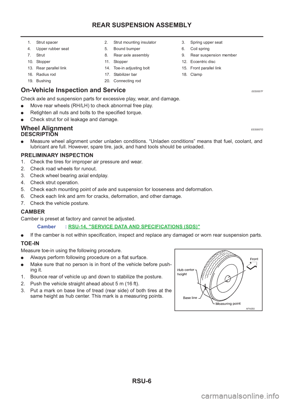
3. Put a mark on base line of tread (rear side) of both tires at the
same height as hub center. This mark is a measuring points.
1. Strut spacer 2. Strut mounting insulator 3. Spring upper seat
4. Upper rubber seat 5. Bound bumper 6. Coil spring
7. Strut 8. Rear axle assembly 9. Rear suspension member
10. Stopper 11. Stopper 12. Eccentric disc
13. Rear parallel link 14. Toe-in adjusting bolt 15. Front parallel link
16. Radius rod 17. Stabilizer bar 18. Clamp
19. Bushing 20. Connecting rod
Camber : RSU-14, "SERVICE DATA AND SPECIFICATIONS (SDS)"
AFA050
Page 2736 of 3833
WT-2
NOISE, VIBRATION, AND HARSHNESS (NVH) TROUBLESHOOTING
NOISE, VIBRATION, AND HARSHNESS (NVH) TROUBLESHOOTING
PFP:00003
NVH Troubleshooting ChartEES000J1
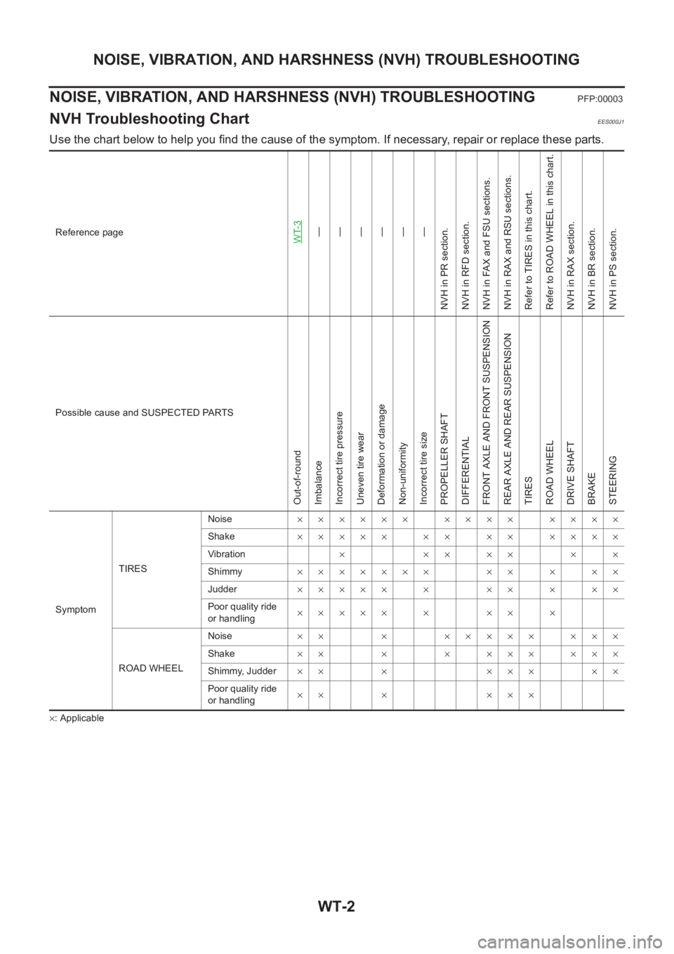
Use the chart below to help you find the cause of the symptom. If necessary, repair or replace these parts.
×: ApplicableReference page
WT-3—
—
—
—
—
—
NVH in PR section.
NVH in RFD section.
NVH in FAX and FSU sections.
NVH in RAX and RSU sections.
Refer to TIRES in this chart.
Refer to ROAD WHEEL in this chart.
NVH in RAX section.
NVH in BR section.
NVH in PS section.
Possible cause and SUSPECTED PARTS
Out-of-round
Imbalance
Incorrect tire pressure
Uneven tire wear
Deformation or damage
Non-uniformity
Incorrect tire size
PROPELLER SHAFT
DIFFERENTIAL
FRONT AXLE AND FRONT SUSPENSION
REAR AXLE AND REAR SUSPENSION
TIRES
ROAD WHEEL
DRIVE SHAFT
BRAKE
STEERING
SymptomTIRESNoise×××××× ×××× ××××
Shake××××× ×× ×× ××××
Vibration×××××××
Shimmy××××××× ×× × ××
Judder××××× × ×× × ××
Poor quality ride
or handling××××× × ×× ×
ROAD WHEELNoise×× × ××××× ×××
Shake×× × × ××× ×××
Shimmy, Judder×× × ××× ××
Poor quality ride
or handling×× × ×××
Page 2739 of 3833
ROAD WHEEL TIRE ASSEMBLY
WT-5
C
D
F
G
H
I
J
K
L
MA
B
WT
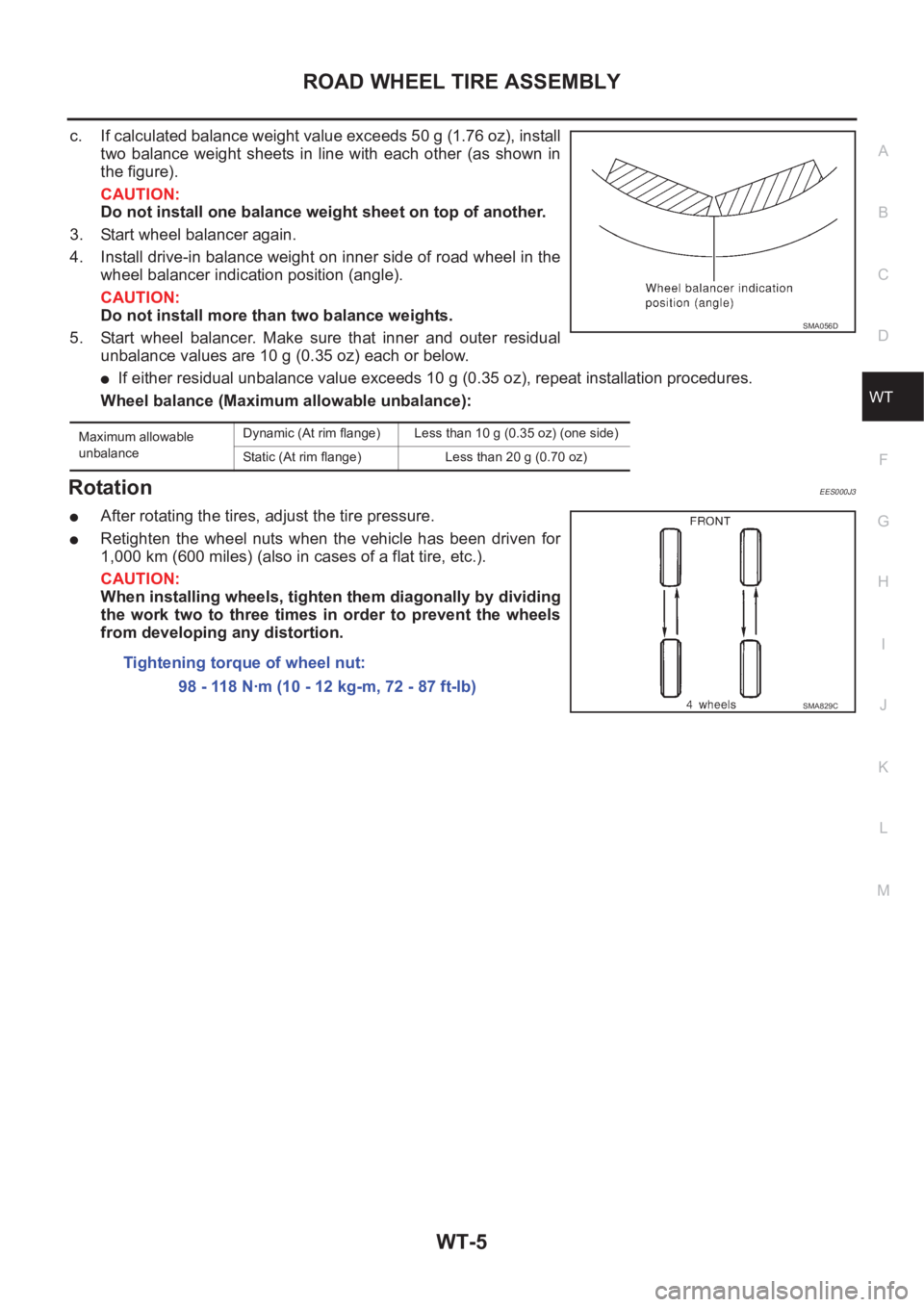
c. If calculated balance weight value exceeds 50 g (1.76 oz), install
two balance weight sheets in line with each other (as shown in
the figure).
CAUTION:
Do not install one balance weight sheet on top of another.
3. Start wheel balancer again.
4. Install drive-in balance weight on inner side of road wheel in the
wheel balancer indication position (angle).
CAUTION:
Do not install more than two balance weights.
5. Start wheel balancer. Make sure that inner and outer residual
unbalance values are 10 g (0.35 oz) each or below.
●If either residual unbalance value exceeds 10 g (0.35 oz), repeat installation procedures.
Wheel balance (Maximum allowable unbalance):
RotationEES000J3
●After rotating the tires, adjust the tire pressure.
●Retighten the wheel nuts when the vehicle has been driven for
1,000 km (600 miles) (also in cases of a flat tire, etc.).
CAUTION:
When installing wheels, tighten them diagonally by dividing
the work two to three times in order to prevent the wheels
from developing any distortion.
Maximum allowable
unbalanceDynamic (At rim flange) Less than 10 g (0.35 oz) (one side)
Static (At rim flange) Less than 20 g (0.70 oz)
SMA056D
Tightening torque of wheel nut:
98 - 118 N·m (10 - 12 kg-m, 72 - 87 ft-lb)
SMA829C