2001 NISSAN X-TRAIL brake fluid
[x] Cancel search: brake fluidPage 120 of 3833
![NISSAN X-TRAIL 2001 Service Repair Manual EM-70
[QR]
ENGINE ASSEMBLY
1. Release fuel pressure. Refer to EC-775, "FUEL PRESSURE RELEASE" [QR20DE (WITH EURO-OBD)],
EC-1139, "
FUEL PRESSURE RELEASE" [QR20DE (WITHOUT EURO NISSAN X-TRAIL 2001 Service Repair Manual EM-70
[QR]
ENGINE ASSEMBLY
1. Release fuel pressure. Refer to EC-775, "FUEL PRESSURE RELEASE" [QR20DE (WITH EURO-OBD)],
EC-1139, "
FUEL PRESSURE RELEASE" [QR20DE (WITHOUT EURO](/manual-img/5/57405/w960_57405-119.png)
EM-70
[QR]
ENGINE ASSEMBLY
1. Release fuel pressure. Refer to EC-775, "FUEL PRESSURE RELEASE" [QR20DE (WITH EURO-OBD)],
EC-1139, "
FUEL PRESSURE RELEASE" [QR20DE (WITHOUT EURO-OBD)], EC-42, "FUEL PRES-
SURE RELEASE" [QR25DE (WITH EURO-OBD)] or EC-452, "FUEL PRESSURE RELEASE" [QR25DE
(WITHOUT EURO-OBD)].
2. Remove engine hood.
3. Drain engine coolant from radiator drain plug. Refer to CO-9, "
DRAINING ENGINE COOLANT" .
4. Remove the following parts.
●LH/RH undercovers
●LH/RH front wheels
●Battery
●Drive belts; Refer to EM-12, "REMOVAL" .
●Air duct and air cleaner case assembly; Refer to EM-14, "REMOVAL" .
●Alternator
●Radiator and radiator fan assembly; Refer to CO-11, "RADIATOR" .
5. Disconnect engine room harness from the engine side and set it aside for easier work.
6. Disconnect all the body-side vacuum hoses and air hoses at engine side.
Engine room LH
7. Disconnect fuel hose, and plug it to prevent fuel from draining. Refer to EM-16, "
INTAKE MANIFOLD"
8. Disconnect heater hose, and install plug it to prevent engine coolant from draining.
9. Disconnect select cable from transaxle (A/T models).
10. Remove clutch operating cylinder from transaxle, and move it aside (M/T models).
11. Disconnect shift cable from transaxle (M/T models).
Engine room RH
12. Remove engine coolant reservoir tank.
13. Remove air conditioner compressor with piping connected from engine. Temporarily secure it on body
with a rope to avoid putting load on it.
Vehicle underbody
14. Remove exhaust front tube.
15. Remove propeller shaft.
16. Remove steering shaft from steering gear.
17. Disconnect power steering fluid cooler piping at a point between body and engine.
18. Remove ABS sensor from brake caliper.
19. Remove brake caliper with piping connected from steering knuckle. Temporarily secure it on body with a
rope to avoid load on it.
20. Remove LH/RH suspensions from steering knuckle under strut.
Removal
21. Install engine slingers into front left of cylinder head and rear right of cylinder head.
●Use alternator bracket mounting bolt holes for the front side.
22. Lift with hoist and secure the engine in position.Slinger bolts:
Front
: 51.0 - 64.7 N·m (5.2 - 6.6 kg-m, 38 - 47 ft-lb)
Rear
: 24.5 - 31.4 N·m (2.5 - 3.2 kg-m, 18 - 23 ft-lb)
SBIA0271E
Page 244 of 3833
![NISSAN X-TRAIL 2001 Service Repair Manual EM-194
[YD22DDTi]
ENGINE ASSEMBLY
REMOVAL
Description of work
Remove engine, transaxle and transfer assembly with front suspension member from vehicle down ward.
Separate suspension membe NISSAN X-TRAIL 2001 Service Repair Manual EM-194
[YD22DDTi]
ENGINE ASSEMBLY
REMOVAL
Description of work
Remove engine, transaxle and transfer assembly with front suspension member from vehicle down ward.
Separate suspension membe](/manual-img/5/57405/w960_57405-243.png)
EM-194
[YD22DDTi]
ENGINE ASSEMBLY
REMOVAL
Description of work
Remove engine, transaxle and transfer assembly with front suspension member from vehicle down ward.
Separate suspension member, and then separate engine and transaxle.
Preparation
1. Remove engine hood.
2. Drain engine coolant from radiator drain plug.
3. Remove the following parts.
●LH/RH undercovers
●LH/RH front wheels
●Battery
●Drive belts; Refer to EM-119, "Removal and Installation" .
●Air duct and air cleaner case assembly; Refer to EM-120, "Removal and Installation" .
●Alternator
●Radiator and radiator fan assembly; Refer to CO-32, "Removal and Installation" .
●Charge air cooler
4. Disconnect engine room harness from the engine side and set it aside for easier work.
5. Disconnect all the body-side vacuum hoses and air hoses at engine side.
Engine room LH
6. Disconnect fuel feed and return hoses, and plug it to prevent fuel from draining.
7. Disconnect heater hose, and install plug it to prevent engine coolant from draining.
8. Remove clutch operating cylinder from transaxle, and move it aside.
9. Disconnect shift cable from transaxle.
Engine room RH
10. Remove engine coolant reservoir tank.
11. Remove air conditioner compressor with piping connected from engine. Temporarily secure it on body
with a rope to avoid putting load on it.
Vehicle underbody
12. Remove exhaust front tube.
13. Remove propeller shaft.
14. Remove steering shaft from steering gear.
15. Disconnect power steering fluid cooler piping at a point between body and engine.
16. Remove ABS sensor from brake caliper.
17. Remove brake caliper with piping connected from steering knuckle. Temporarily secure it on body with a
rope to avoid load on it.
18. Remove LH/RH suspensions from steering knuckle under strut.
Removal
19. Install engine slingers into front right of cylinder head and rear
left of cylinder head.
20. Lift with hoist and secure the engine in position.Slinger bolts:
: 30 - 37 N·m (3.0 - 3.8 kg-m, 22 - 27 ft-lb)
SBIA0191E
Page 1960 of 3833
CL-2
PRECAUTIONS
PRECAUTIONS
PFP:00001
CautionECS004JW
●Recommended fluid is brake fluid “DOT 3” or “DOT 4”.
●Never reuse drained brake fluid.
●Be careful not to splash brake fluid on painted areas.
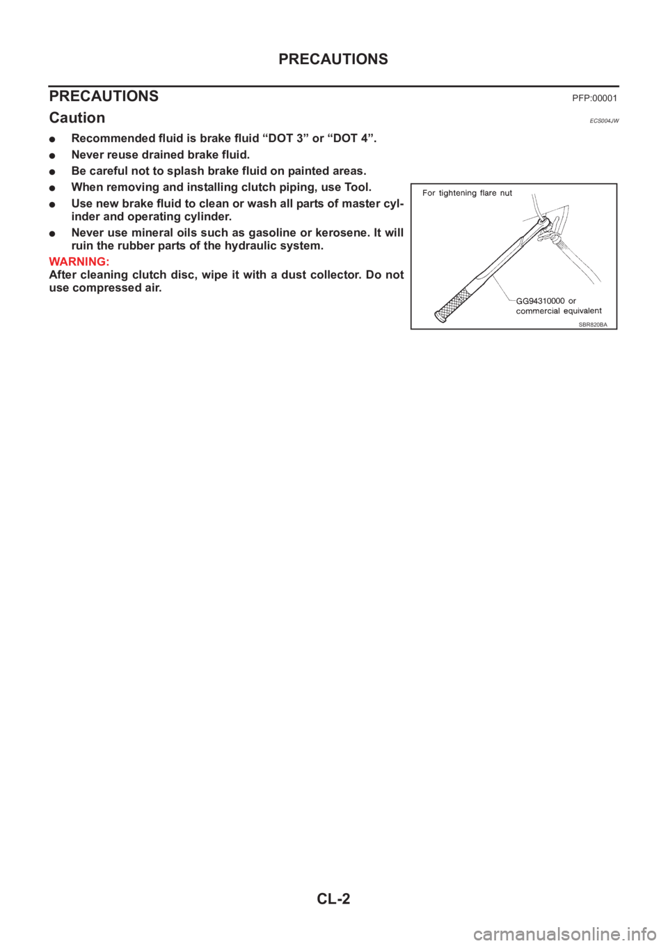
●When removing and installing clutch piping, use Tool.
●Use new brake fluid to clean or wash all parts of master cyl-
inder and operating cylinder.
●Never use mineral oils such as gasoline or kerosene. It will
ruin the rubber parts of the hydraulic system.
WARNING:
After cleaning clutch disc, wipe it with a dust collector. Do not
use compressed air.
SBR820BA
Page 1966 of 3833
CL-8
CLUTCH FLUID
CLUTCH FLUID
PFP:00017
Air Bleeding ProcedureECS008B9
CAUTION:
●Monitor fluid level in the reservoir tank to make sure it does
not empty.
●Do not spill clutch fluid onto painted surfaces. If it spills,
wipe up immediately and wash the affected area with water.
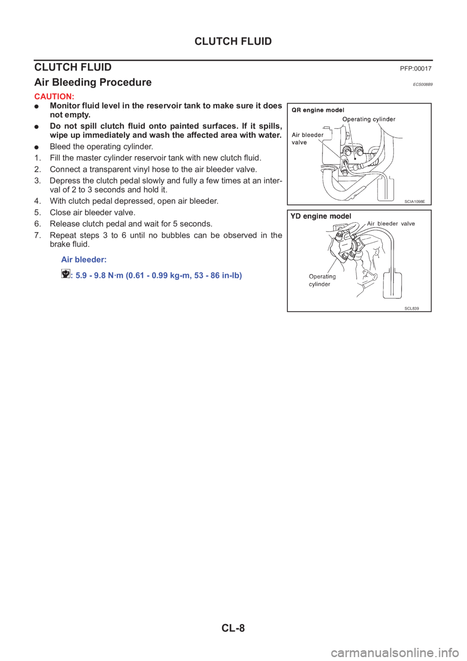
●Bleed the operating cylinder.
1. Fill the master cylinder reservoir tank with new clutch fluid.
2. Connect a transparent vinyl hose to the air bleeder valve.
3. Depress the clutch pedal slowly and fully a few times at an inter-
val of 2 to 3 seconds and hold it.
4. With clutch pedal depressed, open air bleeder.
5. Close air bleeder valve.
6. Release clutch pedal and wait for 5 seconds.
7. Repeat steps 3 to 6 until no bubbles can be observed in the
brake fluid.
Air bleeder:
: 5.9 - 9.8 N·m (0.61 - 0.99 kg-m, 53 - 86 in-lb)
SCIA1098E
SCL839
Page 2080 of 3833
AT-2
DTC P0732 A/T 2ND GEAR FUNCTION ................137
Description ............................................................137
Wiring Diagram — AT — 2ND ..............................140
Diagnostic Procedure ...........................................141
Component Inspection ..........................................142
DTC P0733 A/T 3RD GEAR FUNCTION ................143
Description ............................................................143
Wiring Diagram — AT — 3RD ..............................146
Diagnostic Procedure ...........................................147
Component Inspection ..........................................148
DTC P0734 A/T 4TH GEAR FUNCTION ................149
Description ............................................................149
Wiring Diagram — AT — 4TH ...............................152
Diagnostic Procedure ...........................................153
Component Inspection ..........................................156
DTC P0740 TORQUE CONVERTER CLUTCH
SOLENOID VALVE .................................................158
Description ............................................................158
Wiring Diagram — AT — TCV ..............................160
Diagnostic Procedure ...........................................161
Component Inspection ..........................................162
DTC P0745 LINE PRESSURE SOLENOID VALVE .163
Description ............................................................163
Wiring Diagram — AT — LPSV ............................165
Diagnostic Procedure ...........................................166
Component Inspection ..........................................168
DTC P0750 SHIFT SOLENOID VALVE A ...............170
Description ............................................................170
Wiring Diagram — AT — SSV/A ...........................172
Diagnostic Procedure ...........................................173
Component Inspection ..........................................174
DTC P0755 SHIFT SOLENOID VALVE B ...............175
Description ............................................................175
Wiring Diagram — AT — SSV/B ...........................177
Diagnostic Procedure ...........................................178
Component Inspection ..........................................179
DTC P1705 ACCELERATOR PEDAL POSITION
(APP) SENSOR .......................................................180
Description ............................................................180
Wiring Diagram — AT — TPS ..............................182
Diagnostic Procedure ...........................................183
DTC P1760 OVERRUN CLUTCH SOLENOID
VALVE .....................................................................185
Description ............................................................185
Wiring Diagram — AT — OVRCSV ......................187
Diagnostic Procedure ...........................................188
Component Inspection ..........................................189
DTC U1000 CAN COMMUNICATION LINE ...........
.190
Description ............................................................190
On Board Diagnosis Logic ....................................190
DTC Confirmation Procedure ...............................190
Wiring Diagram — AT — CAN ..............................191
Diagnostic Procedure ...........................................192
DTC BATT/FLUID TEMP SEN (A/T FLUID TEMP
SENSOR CIRCUIT AND TCM POWER SOURCE) .193
Description ............................................................193
Wiring Diagram — AT — BA/FTS .........................195
Diagnostic Procedure ...........................................196
Component Inspection ..........................................198DTC VEHICLE SPEED SENSOR MTR ...................199
Description ............................................................199
Wiring Diagram — AT — VSSMTR .......................201
Diagnostic Procedure ............................................202
DTC CONTROL UNIT (RAM), CONTROL UNIT
(ROM) ......................................................................203
Description ............................................................203
Diagnostic Procedure ............................................203
DTC CONTROL UNIT(EEPROM) ...........................205
Description ............................................................205
Diagnostic Procedure ............................................206
TROUBLE DIAGNOSES FOR SYMPTOMS ...........207
Wiring Diagram — AT — NONDTC ......................207
O/D OFF Indicator Lamp Does Not Come On ......209
Engine Cannot Be Started In “P” and “N” Position .211
In “P” Position, Vehicle Moves Forward Or Back-
ward When Pushed ...............................................212
In “N” Position, Vehicle Moves ..............................213
Large Shock. “N” → “R” Position ..........................214
Vehicle Does Not Creep Backward In “R” Position .215
Vehicle Does Not Creep Forward In “D”, “2” Or “1”
Position .................................................................218
Vehicle Cannot Be Started From D
1 .....................220
A/T Does Not Shift: D
1→ D2 Or Does Not Kickdown:
D
4→ D2 ...............................................................
.223
A/T Does Not Shift: D
2→ D3 ................................225
A/T Does Not Shift: D
3→ D4 ................................227
A/T Does Not Perform Lock-up .............................229
A/T Does Not Hold Lock-up Condition ..................230
Lock-up Is Not Released .......................................232
Engine Speed Does Not Return To Idle (Light Brak-
ing D
4→ D3 ) ........................................................233
Vehicle Does Not Start From D
1 ...........................234
A / T D o e s N o t S h i f t : D
4→ D3 , W h e n O v e r d r i v e C o n -
trol Switch “ON” → “OFF” .....................................236
A/T Does Not Shift: D
3→ 22 , W h e n S e l e c t o r L e v e r
“D” → “2” Position .................................................237
A/T Does Not Shift: 2
2→ 11 , When Selector Lever
“2” → “1” Position ..................................................238
Vehicle Does Not Decelerate By Engine Brake ....240
TCM Self-diagnosis Does Not Activate .................241
EXC.F/EURO-OBD
ON BOARD DIAGNOSTIC SYSTEM DESCRIP-
TION ........................................................................247
CONSULT-II ..........................................................247
Diagnostic Procedure Without CONSULT-II .........253
TROUBLE DIAGNOSIS — INTRODUCTION .........258
Introduction ...........................................................258
Work Flow .............................................................262
TROUBLE DIAGNOSIS — BASIC INSPECTION ...264
A/T Fluid Check ....................................................264
Stall Test ................................................................265
Line Pressure Test ................................................268
Road Test ..............................................................269
TROUBLE DIAGNOSIS — GENERAL DESCRIP-
Page 2081 of 3833
AT-3
D
E
F
G
H
I
J
K
L
MA
B
AT TION ........................................................................ 287
Symptom Chart .................................................... 287
TCM Terminals and Reference Value ................... 306
CAN COMMUNICATION ........................................ 309
System Description .............................................. 309
TROUBLE DIAGNOSES FOR SYMPTOMS .......... 310
Wiring Diagram — AT — NONDTC ...................... 310
O/D OFF Indicator Lamp Does Not Come On ..... 312
Engine Cannot Be Started In “P” and “N” Position . 314
In “P” Position, Vehicle Moves Forward Or Back-
ward When Pushed .............................................. 315
In “N” Position, Vehicle Moves ............................. 315
Large Shock. “N” → “R” Position .......................... 317
Vehicle Does Not Creep Backward In “R” Position . 318
Vehicle Does Not Creep Forward In “D”, “2” Or “1”
Position ................................................................ 321
Vehicle Cannot Be Started From D
1 ..................... 323
A/T Does Not Shift: D
1→ D2 Or Does Not Kick down:
D
4→ D2 ............................................................... 326
A/T Does Not Shift: D
2→ D3 ............................... 328
A/T Does Not Shift: D
3→ D4 ............................... 330
A/T Does Not Perform Lock-up ............................ 332
A/T Does Not Hold Lock-up Condition ................. 333
Lock-up Is Not Released ...................................... 335
Engine Speed Does Not Return To Idle (Light Brak-
ing D
4→ D3 ) ....................................................... 336
Vehicle Does Not Start From D
1 ........................... 338
A/T Does Not Shift: D
4→ D3 , When Overdrive Con-
trol Switch “ON” → “OFF” ..................................... 339
A/T Does Not Shift: D
3→ 22 , W h e n S e l e c t o r L e v e r
“D”→ “2” Position ................................................ 340
A/T Does Not Shift: 2
2→ 11 , W h e n S e l e c t o r L e v e r
“2” → “1” Position ................................................. 341
Vehicle Does Not Decelerate By Engine Brake ... 343
TCM Self-diagnosis Does Not Activate ................ 344
ALL
MAIN POWER SUPPLY AND GROUND CIRCUIT . 350
Wiring Diagram — AT — MAIN ............................ 350
Diagnostic Procedure ........................................... 351
VEHICLE SPEED SENSOR·A/T (REVOLUTION
SENSOR) ................................................................ 353
Description ........................................................... 353
Wiring Diagram — AT — VSSA/T ........................ 355
Diagnostic Procedure ........................................... 356
DTC VEHICLE SPEED SENSOR MTR .................. 358
Description ........................................................... 358
Wiring Diagram — AT — VSSMTR ...................... 360
Diagnostic Procedure ........................................... 361
ACCELE RATOR PEDAL POSITION (APP) SEN-
SOR ........................................................................ 362
Description ........................................................... 362
Wiring Diagram — AT — TPS .............................. 364
Diagnostic Procedure ........................................... 365
SHIFT SOLENOID VALVE A .................................. 367
Description ........................................................... 367
Wiring Diagram — AT — SSV/A .......................... 369Diagnostic Procedure ...........................................370
Component Inspection ..........................................371
SHIFT SOLENOID VALVE B ..................................372
Description ............................................................372
Wiring Diagram — AT — SSV/B ...........................374
Diagnostic Procedure ...........................................375
Component Inspection ..........................................376
OVERRUN CLUTCH SOLENOID VALVE ...............377
Description ............................................................377
Wiring Diagram — AT — OVRCSV ......................378
Diagnostic Procedure ...........................................379
Component Inspection ..........................................380
TORQUE CONVERTER CLUTCH SOLENOID
VALVE .....................................................................381
Description ............................................................381
Wiring Diagram — AT — TCV ..............................383
Diagnostic Procedure ...........................................384
Component Inspection ..........................................385
BATT/FLUID TEMP SEN (A/T FLUID TEMP SEN-
SOR CIRCUIT AND TCM POWER SOURCE) .......386
Description ............................................................386
Wiring Diagram — AT — BA/FTS .........................388
Diagnostic Procedure ...........................................389
Component Inspection ..........................................391
ENGINE SPEED SIGNAL .......................................392
Description ............................................................392
Wiring Diagram — AT — ENGSS .........................393
Diagnostic Procedure ...........................................394
LINE PRESSURE SOLENOID VALVE ..................
.396
Description ............................................................396
Wiring Diagram — AT — LPSV ............................398
Diagnostic Procedure ...........................................399
Component Inspection ..........................................401
CAN COMMUNICATION LINE ...............................403
Description ............................................................403
On Board Diagnosis Logic ....................................403
Self-Diagnosis Code Confirmation Procedure ......403
Wiring Diagram — AT — CAN ..............................404
Diagnostic Procedure ...........................................405
A/T SHIFT LOCK SYSTEM ....................................406
Description ............................................................406
Shift Lock System Electrical Parts Location .........406
Wiring Diagram — SHIFT — ................................407
Diagnostic Procedure ...........................................408
KEY INTERLOCK CABLE ......................................412
Components .........................................................412
Removal ...............................................................412
Installation ............................................................413
ON-VEHICLE SERVICE ..........................................414
Control Valve Assembly and Accumulators ..........414
Control Cable Adjustment .....................................416
Park/Neutral Position (PNP) Switch Adjustment ..416
Differential Side Oil Seal Replacement ................417
Revolution Sensor Replacement ..........................417
REMOVAL AND INSTALLATION ...........................418
Removal ...............................................................418
Installation ............................................................419
OVERHAUL ............................................................421
Components .........................................................421
Page 2082 of 3833
AT-4
Oil Channel ...........................................................424
Locations of Adjusting Shims, Needle Bearings,
Thrust Washers and Snap Rings ..........................425
DISASSEMBLY .......................................................426
Disassembly .........................................................426
REPAIR FOR COMPONENT PARTS ......................441
Manual Shaft ........................................................441
Oil Pump ...............................................................444
Control Valve Assembly ........................................448
Control Valve Upper Body ....................................457
Control Valve Lower Body ....................................461
Reverse Clutch .....................................................463
High Clutch ...........................................................466
Forward and Overrun Clutches ............................471
Low & Reverse Brake ...........................................476
Rear Internal Gear, Forward Clutch Hub and Over-
run Clutch Hub ......................................................479
Output Shaft, Idler Gear, Reduction Pinion Gear and
Bearing Retainer ...................................................483
Band Servo Piston Assembly ...............................488
Final Drive ............................................................493
ASSEMBLY .............................................................498
Assembly (1) .........................................................498
Adjustment (1) ......................................................499
Assembly (2) .........................................................504Adjustment (2) .......................................................510
Assembly (3) .........................................................514
SERVICE DATA AND SPECIFICATIONS (SDS) ....521
General Specifications ......................................... .521
Shift Schedule .......................................................521
Stall Revolution .....................................................522
Line Pressure ........................................................522
Control Valves .......................................................522
Accumulator ..........................................................523
Clutch and Brakes .................................................524
Final Drive .............................................................526
Planetary Carrier and Oil Pump ............................527
Input Shaft .............................................................528
Reduction Pinion Gear ..........................................528
Band Servo ...........................................................529
Output Shaft ..................................................
........529
Bearing Retainer ...................................................529
Total End Play .......................................................529
Reverse Clutch End Play ......................................530
Removal and Installation .......................................530
Shift Solenoid Valves ............................................530
Solenoid Valves ....................................................530
A/T Fluid Temperature Sensor ..............................531
Revolution Sensor .................................................531
Dropping Resistor .................................................531
Page 2091 of 3833
A/T FLUID
AT-13
D
E
F
G
H
I
J
K
L
MA
B
AT
A/T FLUIDPFP:KLE40
Checking A/T FluidECS004Q7
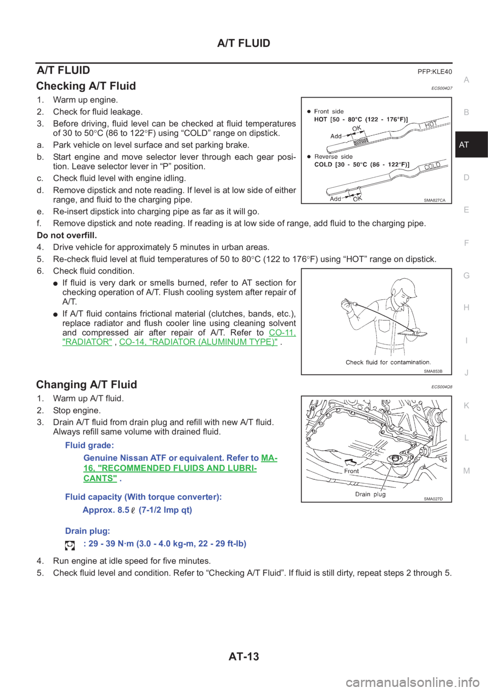
1. Warm up engine.
2. Check for fluid leakage.
3. Before driving, fluid level can be checked at fluid temperatures
of 30 to 50°C (86 to 122°F) using “COLD” range on dipstick.
a. Park vehicle on level surface and set parking brake.
b. Start engine and move selector lever through each gear posi-
tion. Leave selector lever in “P” position.
c. Check fluid level with engine idling.
d. Remove dipstick and note reading. If level is at low side of either
range, and fluid to the charging pipe.
e. Re-insert dipstick into charging pipe as far as it will go.
f. Remove dipstick and note reading. If reading is at low side of range, add fluid to the charging pipe.
Do not overfill.
4. Drive vehicle for approximately 5 minutes in urban areas.
5. Re-check fluid level at fluid temperatures of 50 to 80°C (122 to 176°F) using “HOT” range on dipstick.
6. Check fluid condition.
●If fluid is very dark or smells burned, refer to AT section for
checking operation of A/T. Flush cooling system after repair of
A/T.
●If A/T fluid contains frictional material (clutches, bands, etc.),
replace radiator and flush cooler line using cleaning solvent
and compressed air after repair of A/T. Refer to CO-11,
"RADIATOR" , CO-14, "RADIATOR (ALUMINUM TYPE)" .
Changing A/T FluidECS004Q8
1. Warm up A/T fluid.
2. Stop engine.
3. Drain A/T fluid from drain plug and refill with new A/T fluid.
Always refill same volume with drained fluid.
4. Run engine at idle speed for five minutes.
5. Check fluid level and condition. Refer to “Checking A/T Fluid”. If fluid is still dirty, repeat steps 2 through 5.
SMA827CA
SMA853B
Fluid grade:
Genuine Nissan ATF or equivalent. Refer to MA-
16, "RECOMMENDED FLUIDS AND LUBRI-
CANTS" .
Fluid capacity (With torque converter):
Approx. 8.5 (7-1/2 lmp qt)
Drain plug:
: 29 - 39 N·m (3.0 - 4.0 kg-m, 22 - 29 ft-lb)
SMA027D