2001 NISSAN X-TRAIL open gas tank
[x] Cancel search: open gas tankPage 1867 of 3833
![NISSAN X-TRAIL 2001 Service Repair Manual DTC P1217 OVERHEAT (COOLING SYSTEM)
EC-1517
[YD]
C
D
E
F
G
H
I
J
K
L
MA
EC
5.DETECT MALFUNCTIONING PART
Check the following.
●Harness connectors E64, F5
●Harness for open or short between cooling NISSAN X-TRAIL 2001 Service Repair Manual DTC P1217 OVERHEAT (COOLING SYSTEM)
EC-1517
[YD]
C
D
E
F
G
H
I
J
K
L
MA
EC
5.DETECT MALFUNCTIONING PART
Check the following.
●Harness connectors E64, F5
●Harness for open or short between cooling](/manual-img/5/57405/w960_57405-1866.png)
DTC P1217 OVERHEAT (COOLING SYSTEM)
EC-1517
[YD]
C
D
E
F
G
H
I
J
K
L
MA
EC
5.DETECT MALFUNCTIONING PART
Check the following.
●Harness connectors E64, F5
●Harness for open or short between cooling fan relays-2 and -3 and ECM
>> Repair open circuit or short to ground or short to power in harness or connectors.
6.CHECK COOLING FAN RELAYS-2 AND -3
Refer to EC-1518, "
Component Inspection" .
OK or NG
OK >> GO TO 7.
NG >> Replace cooling fan relays.
7.CHECK COOLING FAN MOTORS
Refer to EC-1518, "
Component Inspection" .
OK or NG
OK >> GO TO 8.
NG >> Replace cooling fan motors.
8.CHECK INTERMITTENT INCIDENT
Perform EC-1441, "
TROUBLE DIAGNOSIS FOR INTERMITTENT INCIDENT" .
>>INSPECTION END
Main 12 Causes of OverheatingEBS004QY
Engine Step Inspection item Equipment Condition Reference page
OFF 1
●Blocked radiator
●Blocked radiator grille
●Blocked bumper
●Visual No blocking —
2
●Coolant mixture●Coolant tester 50 - 50% coolant mixture See MA-16, "RECOM-
MENDED FLUIDS AND
LUBRICANTS" .
3
●Coolant level●Visual Coolant up to MAX level
in reservoir tank and radi-
ator filler neckSee MA-27, "Changing
Engine Coolant" .
4
●Radiator cap●Pressure tester 78 - 98 kPa (0.78 - 0.98
ba r, 0.8 - 1.0 kg/cm2 , 11 -
14 psi)See CO-33, "
Checking
Radiator Cap" .
ON*
25●Coolant leaks●Visual No leaks See CO-29, "CHECKING
RADIATOR SYSTEM
FOR LEAKS" .
ON*
26●Thermostat●Touch the upper and
lower radiator hosesBoth hoses should be hot See CO-41, "THERMO-
STAT AND WATER PIP-
ING" .
ON*
17●Cooling fan●CONSULT-II Operating See Trouble Diagnosis for
DTC P1217, EC-1458
.
OFF 8
●Combustion gas leak●Color checker chemi-
cal tester 4 Gas ana-
lyzerNegative —
Page 3281 of 3833
PRECAUTIONS
ATC-5
C
D
E
F
G
H
I
K
L
MA
B
AT C
General Refrigerant PrecautionsEJS000T2
WARNING:
●Do not release refrigerant into the air. Use approved recovery/recycling equipment to capture the
refrigerant every time an air conditioning system is discharged.
●Always wear eye and hand protection (goggles and gloves) when working with any refrigerant or
air conditioning system.
●Do not store or heat refrigerant containers above 52°C (125°F).
●Do not heat a refrigerant container with an open flame; if container warming is required, place the
bottom of the container in a warm pail of water.
●Do not intentionally drop, puncture, or incinerate refrigerant containers.
●Keep refrigerant away from open flames: poisonous gas will be produced if refrigerant burns.
●Refrigerant will displace oxygen, therefore be certain to work in well ventilated areas to prevent
suffocation.
●Do not pressure test or leak test HFC-134a (R-134a) service equipment and/or vehicle air condi-
tioning systems with compressed air during repair. Some mixtures of air and HFC-134a (R-134a)
have been shown to be combustible at elevated pressures. These mixtures, if ignited, may cause
injury or property damage. Additional health and safety information may be obtained from refriger-
ant manufacturers.
Lubricant PrecautionsEJS0027Y
●Use only specified lubricant for the HFC-134a (R-134a) A/C system and HFC-134a (R-134a) components.
If lubricant other than that specified is used, compressor malfunction is likely to occur.
●The specified HFC-134a (R-134a) lubricant rapidly absorbs moisture from the atmosphere. The following
handling precautions must be observed:
●When removing refrigerant components from a vehicle, immediately cap (seal) the component to minimize
the entry of moisture from the atmosphere.
●When installing refrigerant components to a vehicle, do not remove the caps (unseal) until just before con-
necting the components. Connect all refrigerant loop components as quickly as possible to minimize the
entry of moisture into system.
●Only use the specified lubricant from a sealed container. Immediately reseal containers of lubricant. With-
out proper sealing, lubricant will become moisture saturated and should not be used.
●Avoid breathing A/C refrigerant and lubricant vapor or mist. Exposure may irritate eyes, nose and throat.
Remove HFC-134a (R-134a) from the A/C system, using certified service equipment meeting require-
ments of SAE J2210 HFC-134a (R-134a) recycling equipment, or J2209 HFC-134a (R-134a) recovery
equipment. If accidental system discharge occurs, ventilate work area before resuming service. Additional
health and safety information may be obtained from refrigerant and lubricant manufacturers.
●Do not allow lubricant (Nissan A/C System Oil Type S or R) to come in contact with styrofoam parts. Dam-
age may result.
Precautions for Refrigerant ConnectionEJS000T4
A new type refrigerant connection has been introduced to all refrigerant lines except the following location.
●Expansion valve to cooling unit
●Refrigerant pressure sensor to liquid tank
Page 3294 of 3833
ATC-18
REFRIGERATION SYSTEM
REFRIGERATION SYSTEM
PFP:KA990
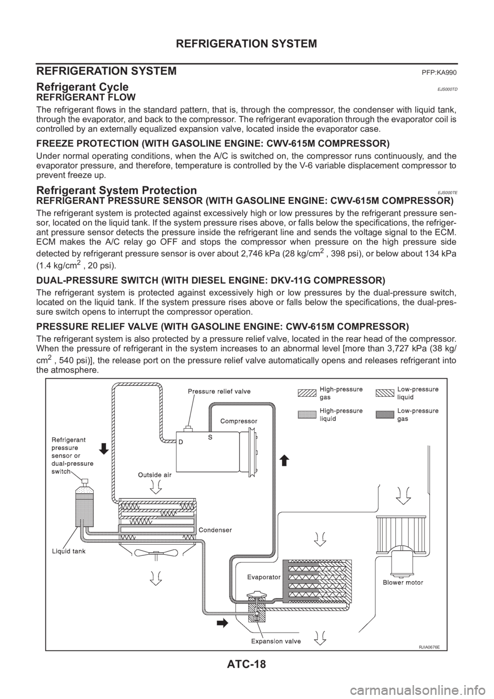
Refrigerant CycleEJS000TD
REFRIGERANT FLOW
The refrigerant flows in the standard pattern, that is, through the compressor, the condenser with liquid tank,
through the evaporator, and back to the compressor. The refrigerant evaporation through the evaporator coil is
controlled by an externally equalized expansion valve, located inside the evaporator case.
FREEZE PROTECTION (WITH GASOLINE ENGINE: CWV-615M COMPRESSOR)
Under normal operating conditions, when the A/C is switched on, the compressor runs continuously, and the
evaporator pressure, and therefore, temperature is controlled by the V-6 variable displacement compressor to
prevent freeze up.
Refrigerant System ProtectionEJS000TE
REFRIGERANT PRESSURE SENSOR (WITH GASOLINE ENGINE: CWV-615M COMPRESSOR)
The refrigerant system is protected against excessively high or low pressures by the refrigerant pressure sen-
sor, located on the liquid tank. If the system pressure rises above, or falls below the specifications, the refriger-
ant pressure sensor detects the pressure inside the refrigerant line and sends the voltage signal to the ECM.
ECM makes the A/C relay go OFF and stops the compressor when pressure on the high pressure side
detected by refrigerant pressure sensor is over about 2,746 kPa (28 kg/cm
2 , 398 psi), or below about 134 kPa
(1.4 kg/cm
2 , 20 psi).
DUAL-PRESSURE SWITCH (WITH DIESEL ENGINE: DKV-11G COMPRESSOR)
The refrigerant system is protected against excessively high or low pressures by the dual-pressure switch,
located on the liquid tank. If the system pressure rises above or falls below the specifications, the dual-pres-
sure switch opens to interrupt the compressor operation.
PRESSURE RELIEF VALVE (WITH GASOLINE ENGINE: CWV-615M COMPRESSOR)
The refrigerant system is also protected by a pressure relief valve, located in the rear head of the compressor.
When the pressure of refrigerant in the system increases to an abnormal level [more than 3,727 kPa (38 kg/
cm
2 , 540 psi)], the release port on the pressure relief valve automatically opens and releases refrigerant into
the atmosphere.
RJIA0676E
Page 3575 of 3833
COMBINATION METERS (LHD MODELS)
DI-17
C
D
E
F
G
H
I
J
L
MA
B
DI
Inspection/Fuel Level Sensor UnitEKS002ZI
FUEL LEVEL SENSOR UNIT
The following symptoms do not indicate a malfunction.
●Depending on vehicle posture or driving circumstance, the fuel level in the tank varies, and the pointer
may fluctuate.
●If the vehicle is fueled with the ignition switch ON, the pointer will move slowly.
LOW-FUEL WARNING LAMP
Depending on vehicle posture or driving circumstance, the fuel level in the tank varies, and the warning lamp
ON timing may be changed.
1.DIAGNOSIS MODE INSPECTION
Preform the combination meter diagnosis mode. Refer to DI-10, "
Meter/Gauge Operation and Odo/Trip Meter
Segment Check in Diagnosis Mode" .
OK or NG
OK >> GO TO 2.
NG >> Replace combination meter.
2.HARNESS CONNECTOR INSPECTION
1. Turn the ignition switch OFF.
2. Check combination meter, fuel level sensor unit and terminals (meter-side, module-side, and harness-
side) for poor connection and bend.
OK or NG
OK >> GO TO 3.
NG >> Repair or replace terminals or connectors.
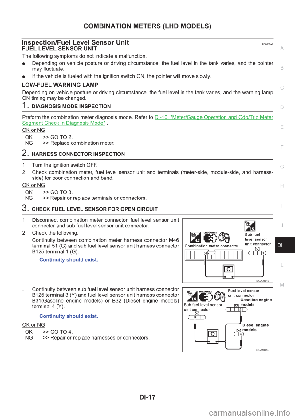
3.CHECK FUEL LEVEL SENSOR FOR OPEN CIRCUIT
1. Disconnect combination meter connector, fuel level sensor unit
connector and sub fuel level sensor unit connector.
2. Check the following.
–Continuity between combination meter harness connector M46
terminal 51 (G) and sub fuel level sensor unit harness connector
B125 terminal 1 (G).
–Continuity between sub fuel level sensor unit harness connector
B125 terminal 3 (Y) and fuel level sensor unit harness connector
B31(Gasoline engine models) or B32 (Diesel engine models)
terminal 4 (Y).
OK or NG
OK >> GO TO 4.
NG >> Repair or replace harnesses or connectors.Continuity should exist.
SKIA0991E
Continuity should exist.
SKIA1005E
Page 3595 of 3833
COMBINATION METERS (RHD MODELS)
DI-37
C
D
E
F
G
H
I
J
L
MA
B
DI
Inspection/Fuel Level Sensor UnitEKS0030T
FUEL LEVEL SENSOR UNIT
The following symptoms do not indicate a malfunction.
●Depending on vehicle posture or driving circumstance, the fuel level in the tank varies, and the pointer
may fluctuate.
●If the vehicle is fueled with the ignition switch ON, the pointer will move slowly.
LOW-FUEL WARNING LAMP
Depending on vehicle posture or driving circumstance, the fuel level in the tank varies, and the warning lamp
ON timing may be changed.
1.DIAGNOSIS MODE INSPECTION
Preform the combination meter diagnosis mode. Refer to DI-30, "
Meter/Gauge Operation and Odo/Trip Meter
Segment Check in Diagnosis Mode" .
OK or NG
OK >> GO TO 2.
NG >> Replace combination meter.
2.HARNESS CONNECTOR INSPECTION
1. Turn the ignition switch OFF.
2. Check combination meter, fuel level sensor unit and terminals (meter-side, module-side, and harness-
side) for poor connection and bend.
OK or NG
OK >> GO TO 3.
NG >> Repair terminals or connectors.
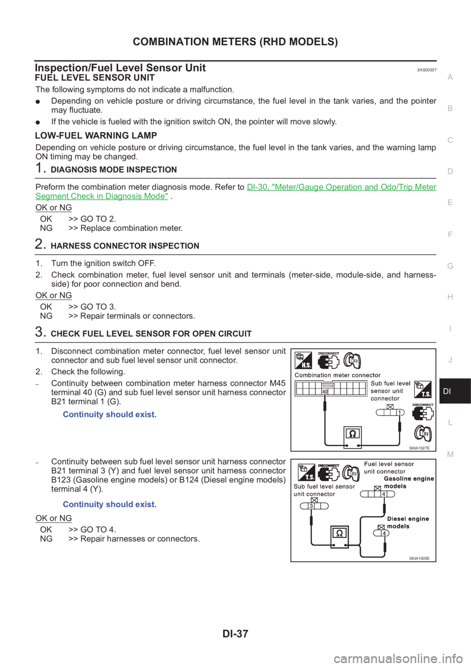
3.CHECK FUEL LEVEL SENSOR FOR OPEN CIRCUIT
1. Disconnect combination meter connector, fuel level sensor unit
connector and sub fuel level sensor unit connector.
2. Check the following.
–Continuity between combination meter harness connector M45
terminal 40 (G) and sub fuel level sensor unit harness connector
B21 terminal 1 (G).
–Continuity between sub fuel level sensor unit harness connector
B21 terminal 3 (Y) and fuel level sensor unit harness connector
B123 (Gasoline engine models) or B124 (Diesel engine models)
terminal 4 (Y).
OK or NG
OK >> GO TO 4.
NG >> Repair harnesses or connectors.Continuity should exist.
SKIA1027E
Continuity should exist.
SKIA1005E
Page 3800 of 3833
MA-20
ENGINE MAINTENANCE (QR20DE·QR25DE)
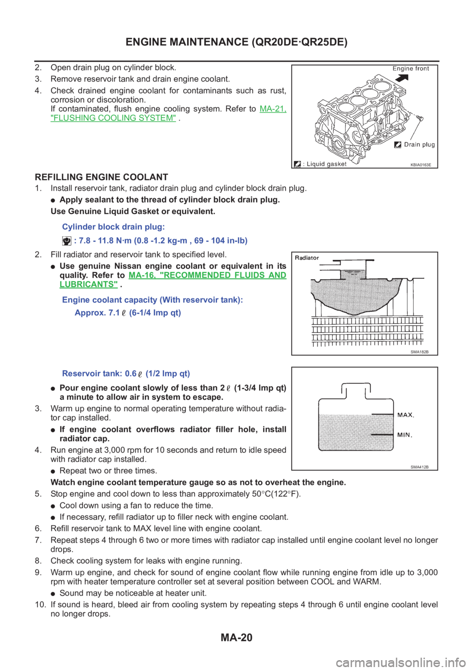
2. Open drain plug on cylinder block.
3. Remove reservoir tank and drain engine coolant.
4. Check drained engine coolant for contaminants such as rust,
corrosion or discoloration.
If contaminated, flush engine cooling system. Refer to MA-21,
"FLUSHING COOLING SYSTEM" .
REFILLING ENGINE COOLANT
1. Install reservoir tank, radiator drain plug and cylinder block drain plug.
●Apply sealant to the thread of cylinder block drain plug.
Use Genuine Liquid Gasket or equivalent.
2. Fill radiator and reservoir tank to specified level.
●Use genuine Nissan engine coolant or equivalent in its
quality. Refer to MA-16, "
RECOMMENDED FLUIDS AND
LUBRICANTS" .
●Pour engine coolant slowly of less than 2 (1-3/4 lmp qt)
a minute to allow air in system to escape.
3. Warm up engine to normal operating temperature without radia-
tor cap installed.
●If engine coolant overflows radiator filler hole, install
radiator cap.
4. Run engine at 3,000 rpm for 10 seconds and return to idle speed
with radiator cap installed.
●Repeat two or three times.
Watch engine coolant temperature gauge so as not to overheat the engine.
5. Stop engine and cool down to less than approximately 50°C(122°F).
●Cool down using a fan to reduce the time.
●If necessary, refill radiator up to filler neck with engine coolant.
6. Refill reservoir tank to MAX level line with engine coolant.
7. Repeat steps 4 through 6 two or more times with radiator cap installed until engine coolant level no longer
drops.
8. Check cooling system for leaks with engine running.
9. Warm up engine, and check for sound of engine coolant flow while running engine from idle up to 3,000
rpm with heater temperature controller set at several position between COOL and WARM.
●Sound may be noticeable at heater unit.
10. If sound is heard, bleed air from cooling system by repeating steps 4 through 6 until engine coolant level
no longer drops.
KBIA0163E
Cylinder block drain plug:
: 7.8 - 11.8 N·m (0.8 -1.2 kg-m , 69 - 104 in-lb)
Engine coolant capacity (With reservoir tank):
Approx. 7.1 (6-1/4 Imp qt)
SMA182B
Reservoir tank: 0.6 (1/2 lmp qt)
SMA412B
Page 3808 of 3833
MA-28
ENGINE MAINTENANCE (YD22DDTI)
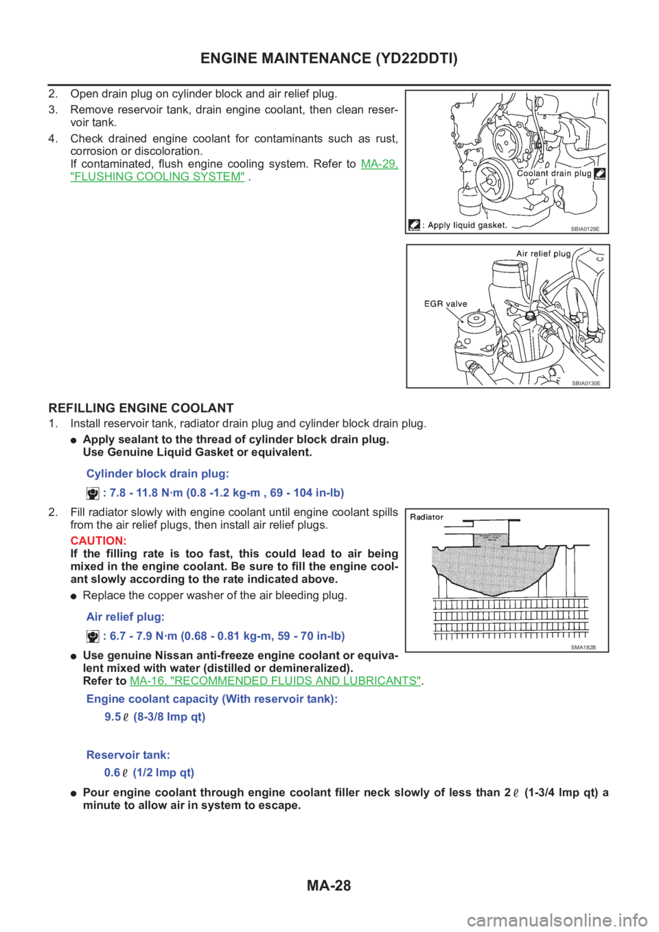
2. Open drain plug on cylinder block and air relief plug.
3. Remove reservoir tank, drain engine coolant, then clean reser-
voir tank.
4. Check drained engine coolant for contaminants such as rust,
corrosion or discoloration.
If contaminated, flush engine cooling system. Refer to MA-29,
"FLUSHING COOLING SYSTEM" .
REFILLING ENGINE COOLANT
1. Install reservoir tank, radiator drain plug and cylinder block drain plug.
●Apply sealant to the thread of cylinder block drain plug.
Use Genuine Liquid Gasket or equivalent.
2. Fill radiator slowly with engine coolant until engine coolant spills
from the air relief plugs, then install air relief plugs.
CAUTION:
If the filling rate is too fast, this could lead to air being
mixed in the engine coolant. Be sure to fill the engine cool-
ant slowly according to the rate indicated above.
●Replace the copper washer of the air bleeding plug.
●Use genuine Nissan anti-freeze engine coolant or equiva-
lent mixed with water (distilled or demineralized).
Refer to MA-16, "
RECOMMENDED FLUIDS AND LUBRICANTS".
●Pour engine coolant through engine coolant filler neck slowly of less than 2 (1-3/4 lmp qt) a
minute to allow air in system to escape.
SBIA0129E
SBIA0130E
Cylinder block drain plug:
: 7.8 - 11.8 N·m (0.8 -1.2 kg-m , 69 - 104 in-lb)
Air relief plug:
: 6.7 - 7.9 N·m (0.68 - 0.81 kg-m, 59 - 70 in-lb)
Engine coolant capacity (With reservoir tank):
9.5 (8-3/8 Imp qt)
SMA182B
Reservoir tank:
0.6 (1/2 lmp qt)