2001 NISSAN X-TRAIL brake sensor
[x] Cancel search: brake sensorPage 120 of 3833
![NISSAN X-TRAIL 2001 Service Repair Manual EM-70
[QR]
ENGINE ASSEMBLY
1. Release fuel pressure. Refer to EC-775, "FUEL PRESSURE RELEASE" [QR20DE (WITH EURO-OBD)],
EC-1139, "
FUEL PRESSURE RELEASE" [QR20DE (WITHOUT EURO NISSAN X-TRAIL 2001 Service Repair Manual EM-70
[QR]
ENGINE ASSEMBLY
1. Release fuel pressure. Refer to EC-775, "FUEL PRESSURE RELEASE" [QR20DE (WITH EURO-OBD)],
EC-1139, "
FUEL PRESSURE RELEASE" [QR20DE (WITHOUT EURO](/manual-img/5/57405/w960_57405-119.png)
EM-70
[QR]
ENGINE ASSEMBLY
1. Release fuel pressure. Refer to EC-775, "FUEL PRESSURE RELEASE" [QR20DE (WITH EURO-OBD)],
EC-1139, "
FUEL PRESSURE RELEASE" [QR20DE (WITHOUT EURO-OBD)], EC-42, "FUEL PRES-
SURE RELEASE" [QR25DE (WITH EURO-OBD)] or EC-452, "FUEL PRESSURE RELEASE" [QR25DE
(WITHOUT EURO-OBD)].
2. Remove engine hood.
3. Drain engine coolant from radiator drain plug. Refer to CO-9, "
DRAINING ENGINE COOLANT" .
4. Remove the following parts.
●LH/RH undercovers
●LH/RH front wheels
●Battery
●Drive belts; Refer to EM-12, "REMOVAL" .
●Air duct and air cleaner case assembly; Refer to EM-14, "REMOVAL" .
●Alternator
●Radiator and radiator fan assembly; Refer to CO-11, "RADIATOR" .
5. Disconnect engine room harness from the engine side and set it aside for easier work.
6. Disconnect all the body-side vacuum hoses and air hoses at engine side.
Engine room LH
7. Disconnect fuel hose, and plug it to prevent fuel from draining. Refer to EM-16, "
INTAKE MANIFOLD"
8. Disconnect heater hose, and install plug it to prevent engine coolant from draining.
9. Disconnect select cable from transaxle (A/T models).
10. Remove clutch operating cylinder from transaxle, and move it aside (M/T models).
11. Disconnect shift cable from transaxle (M/T models).
Engine room RH
12. Remove engine coolant reservoir tank.
13. Remove air conditioner compressor with piping connected from engine. Temporarily secure it on body
with a rope to avoid putting load on it.
Vehicle underbody
14. Remove exhaust front tube.
15. Remove propeller shaft.
16. Remove steering shaft from steering gear.
17. Disconnect power steering fluid cooler piping at a point between body and engine.
18. Remove ABS sensor from brake caliper.
19. Remove brake caliper with piping connected from steering knuckle. Temporarily secure it on body with a
rope to avoid load on it.
20. Remove LH/RH suspensions from steering knuckle under strut.
Removal
21. Install engine slingers into front left of cylinder head and rear right of cylinder head.
●Use alternator bracket mounting bolt holes for the front side.
22. Lift with hoist and secure the engine in position.Slinger bolts:
Front
: 51.0 - 64.7 N·m (5.2 - 6.6 kg-m, 38 - 47 ft-lb)
Rear
: 24.5 - 31.4 N·m (2.5 - 3.2 kg-m, 18 - 23 ft-lb)
SBIA0271E
Page 244 of 3833
![NISSAN X-TRAIL 2001 Service Repair Manual EM-194
[YD22DDTi]
ENGINE ASSEMBLY
REMOVAL
Description of work
Remove engine, transaxle and transfer assembly with front suspension member from vehicle down ward.
Separate suspension membe NISSAN X-TRAIL 2001 Service Repair Manual EM-194
[YD22DDTi]
ENGINE ASSEMBLY
REMOVAL
Description of work
Remove engine, transaxle and transfer assembly with front suspension member from vehicle down ward.
Separate suspension membe](/manual-img/5/57405/w960_57405-243.png)
EM-194
[YD22DDTi]
ENGINE ASSEMBLY
REMOVAL
Description of work
Remove engine, transaxle and transfer assembly with front suspension member from vehicle down ward.
Separate suspension member, and then separate engine and transaxle.
Preparation
1. Remove engine hood.
2. Drain engine coolant from radiator drain plug.
3. Remove the following parts.
●LH/RH undercovers
●LH/RH front wheels
●Battery
●Drive belts; Refer to EM-119, "Removal and Installation" .
●Air duct and air cleaner case assembly; Refer to EM-120, "Removal and Installation" .
●Alternator
●Radiator and radiator fan assembly; Refer to CO-32, "Removal and Installation" .
●Charge air cooler
4. Disconnect engine room harness from the engine side and set it aside for easier work.
5. Disconnect all the body-side vacuum hoses and air hoses at engine side.
Engine room LH
6. Disconnect fuel feed and return hoses, and plug it to prevent fuel from draining.
7. Disconnect heater hose, and install plug it to prevent engine coolant from draining.
8. Remove clutch operating cylinder from transaxle, and move it aside.
9. Disconnect shift cable from transaxle.
Engine room RH
10. Remove engine coolant reservoir tank.
11. Remove air conditioner compressor with piping connected from engine. Temporarily secure it on body
with a rope to avoid putting load on it.
Vehicle underbody
12. Remove exhaust front tube.
13. Remove propeller shaft.
14. Remove steering shaft from steering gear.
15. Disconnect power steering fluid cooler piping at a point between body and engine.
16. Remove ABS sensor from brake caliper.
17. Remove brake caliper with piping connected from steering knuckle. Temporarily secure it on body with a
rope to avoid load on it.
18. Remove LH/RH suspensions from steering knuckle under strut.
Removal
19. Install engine slingers into front right of cylinder head and rear
left of cylinder head.
20. Lift with hoist and secure the engine in position.Slinger bolts:
: 30 - 37 N·m (3.0 - 3.8 kg-m, 22 - 27 ft-lb)
SBIA0191E
Page 355 of 3833

EC-5
C
D
E
F
G
H
I
J
K
L
M
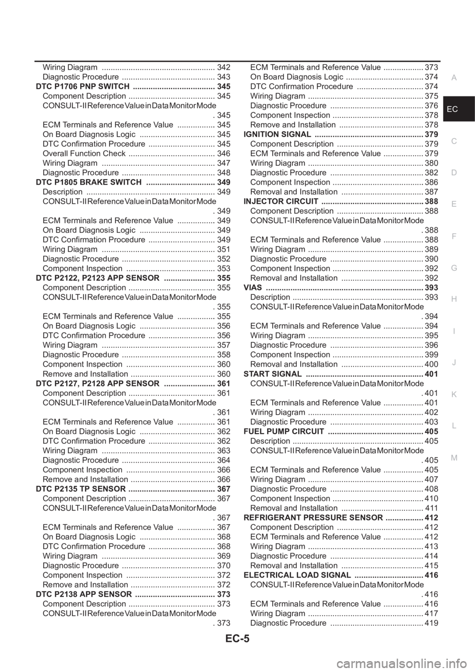
ECA Wiring Diagram .................................................... 342
Diagnostic Procedure ........................................... 343
DTC P1706 PNP SWITCH ...................................... 345
Component Description ........................................ 345
CONSULT-II Reference Value in Data Monitor Mode
. 345
ECM Terminals and Reference Value .................. 345
On Board Diagnosis Logic ................................... 345
DTC Confirmation Procedure ............................... 345
Overall Function Check ........................................ 346
Wiring Diagram .................................................... 347
Diagnostic Procedure ........................................... 348
DTC P1805 BRAKE SWITCH ................................ 349
Description ........................................................... 349
CONSULT-II Reference Value in Data Monitor Mode
. 349
ECM Terminals and Reference Value .................. 349
On Board Diagnosis Logic ................................... 349
DTC Confirmation Procedure ............................... 349
Wiring Diagram .................................................... 351
Diagnostic Procedure ........................................... 352
Component Inspection ......................................... 353
DTC P2122, P2123 APP SENSOR ........................ 355
Component Description ........................................ 355
CONSULT-II Reference Value in Data Monitor Mode
. 355
ECM Terminals and Reference Value .................. 355
On Board Diagnosis Logic ................................... 356
DTC Confirmation Procedure ............................... 356
Wiring Diagram .................................................... 357
Diagnostic Procedure ........................................... 358
Component Inspection ......................................... 360
Remove and Installation ....................................... 360
DTC P2127, P2128 APP SENSOR ........................ 361
Component Description ........................................ 361
CONSULT-II Reference Value in Data Monitor Mode
. 361
ECM Terminals and Reference Value .................. 361
On Board Diagnosis Logic ................................... 362
DTC Confirmation Procedure ............................... 362
Wiring Diagram .................................................... 363
Diagnostic Procedure ........................................... 364
Component Inspection ......................................... 366
Remove and Installation ....................................... 366
DTC P2135 TP SENSOR ........................................ 367
Component Description ........................................ 367
CONSULT-II Reference Value in Data Monitor Mode
. 367
ECM Terminals and Reference Value .................. 367
On Board Diagnosis Logic ................................... 368
DTC Confirmation Procedure ............................... 368
Wiring Diagram ................................................
.... 369
Diagnostic Procedure ........................................... 370
Component Inspection ......................................... 372
Remove and Installation ....................................... 372
DTC P2138 APP SENSOR ..................................... 373
Component Description ........................................ 373
CONSULT-II Reference Value in Data Monitor Mode
. 373ECM Terminals and Reference Value ...................373
On Board Diagnosis Logic ....................................374
DTC Confirmation Procedure ...............................374
Wiring Diagram .....................................................375
Diagnostic Procedure ...........................................376
Component Inspection ..........................................378
Remove and Installation .......................................378
IGNITION SIGNAL ..................................................379
Component Description ........................................379
ECM Terminals and Reference Value ...................379
Wiring Diagram .....................................................380
Diagnostic Procedure ...........................................382
Component Inspection ..........................................386
Removal and Installation ......................................387
INJECTOR CIRCUIT ...............................................388
Component Description ........................................388
CONSULT-II Reference Value in Data Monitor Mode
.388
ECM Terminals and Reference Value ...................388
Wiring Diagram .....................................................389
Diagnostic Procedure ...........................................390
Component Inspection ..........................................392
Removal and Installation ......................................392
VIAS ........................................................................393
Description ............................................................393
CONSULT-II Reference Value in Data Monitor Mode
.394
ECM Terminals and Reference Value ...................394
Wiring Diagram .....................................................395
Diagnostic Procedure ...........................................396
Component Inspection ..........................................399
Removal and Installation ......................................400
START SIGNAL ......................................................401
CONSULT-II Reference Value in Data Monitor Mode
.401
ECM Terminals and Reference Value ...................401
Wiring Diagram .....................................................402
Diagnostic Procedure ...........................................403
FUEL PUMP CIRCUIT ............................................405
Description ............................................................405
CONSULT-II Reference Value in Data Monitor Mode
.405
ECM Terminals and Reference Value ..................
.405
Wiring Diagram .....................................................407
Diagnostic Procedure ...........................................408
Component Inspection ..........................................410
Removal and Installation ......................................411
REFRIGERANT PRESSURE SENSOR ..................412
Component Description ........................................412
ECM Terminals and Reference Value ...................412
Wiring Diagram .....................................................413
Diagnostic Procedure ...........................................414
Removal and Installation ......................................415
ELECTRICAL LOAD SIGNAL ................................416
CONSULT-II Reference Value in Data Monitor Mode
.416
ECM Terminals and Reference Value ...................416
Wiring Diagram .....................................................417
Diagnostic Procedure ...........................................419
Page 358 of 3833

EC-8
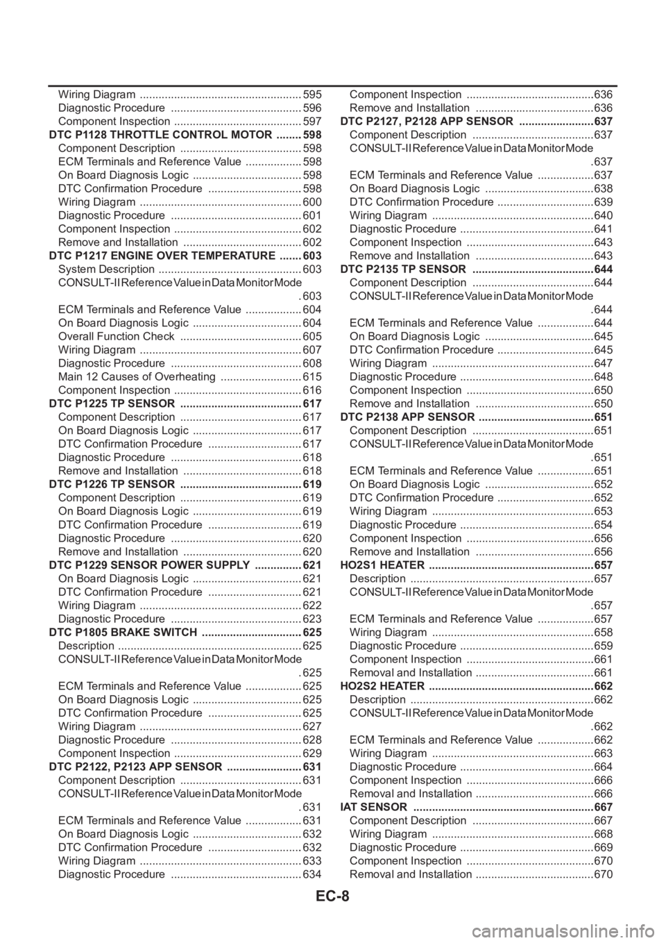
Wiring Diagram .....................................................595
Diagnostic Procedure ...........................................596
Component Inspection ..........................................597
DTC P1128 THROTTLE CONTROL MOTOR .........598
Component Description ........................................598
ECM Terminals and Reference Value ...................598
On Board Diagnosis Logic ....................................598
DTC Confirmation Procedure ...............................598
Wiring Diagram .....................................................600
Diagnostic Procedure ...........................................601
Component Inspection ..........................................602
Remove and Installation .......................................602
DTC P1217 ENGINE OVER TEMPERATURE ........603
System Description ...............................................603
CONSULT-II Reference Value in Data Monitor Mode
.603
ECM Terminals and Reference Value ...................604
On Board Diagnosis Logic ....................................604
Overall Function Check ........................................605
Wiring Diagram .....................................................607
Diagnostic Procedure ...........................................608
Main 12 Causes of Overheating ...........................615
Component Inspection ..........................................616
DTC P1225 TP SENSOR ........................................617
Component Description ........................................617
On Board Diagnosis Logic ....................................617
DTC Confirmation Procedure ...............................617
Diagnostic Procedure ...........................................618
Remove and Installation .......................................618
DTC P1226 TP SENSOR ........................................619
Component Description ........................................619
On Board Diagnosis Logic ....................................619
DTC Confirmation Procedure ...............................619
Diagnostic Procedure ...........................................620
Remove and Installation .......................................620
DTC P1229 SENSOR POWER SUPPLY ................621
On Board Diagnosis Logic ....................................621
DTC Confirmation Procedure ...............................621
Wiring Diagram .....................................................622
Diagnostic Procedure ...........................................623
DTC P1805 BRAKE SWITCH .................................625
Description ............................................................625
CONSULT-II Reference Value in Data Monitor Mode
.625
ECM Terminals and Reference Value ...................625
On Board Diagnosis Logic ....................................625
DTC Confirmation Procedure ...............................625
Wiring Diagram .....................................................627
Diagnostic Procedure ...........................................628
Component Inspection ..........................................629
DTC P2122, P2123 APP SENSOR .........................631
Component Description ........................................631
CONSULT-II Reference Value in Data Monitor Mode
.631
ECM Terminals and Reference Value ...................631
On Board Diagnosis Logic ....................................632
DTC Confirmation Procedure ...............................632
Wiring Diagram .....................................................633
Diagnostic Procedure ...........................................634Component Inspection ..........................................636
Remove and Installation .......................................636
DTC P2127, P2128 APP SENSOR .........................637
Component Description ........................................637
CONSULT-II Reference Value in Data Monitor Mode
.637
ECM Terminals and Reference Value ...................637
On Board Diagnosis Logic ....................................638
DTC Confirmation Procedure ................................639
Wiring Diagram .....................................................640
Diagnostic Procedure ............................................641
Component Inspection ..........................................643
Remove and Installation .......................................643
DTC P2135 TP SENSOR ........................................644
Component Description ........................................644
CONSULT-II Reference Value in Data Monitor Mode
.644
ECM Terminals and Reference Value ...................644
On Board Diagnosis Logic ....................................645
DTC Confirmation Procedure ................................645
Wiring Diagram .....................................................647
Diagnostic Procedure ............................................648
Component Inspection ..........................................650
Remove and Installation .......................................650
DTC P2138 APP SENSOR ......................................651
Component Description ........................................651
CONSULT-II Reference Value in Data Monitor Mode
.651
ECM Terminals and Reference Value ...................651
On Board Diagnosis Logic ....................................652
DTC Confirmation Procedure ................................652
Wiring Diagram .....................................................653
Diagnostic Procedure ............................................654
Component Inspection ..........................................656
Remove and Installation .......................................656
HO2S1 HEATER ......................................................657
Description ............................................................657
CONSULT-II Reference Value in Data Monitor Mode
.657
ECM Terminals and Reference Value ...................657
Wiring Diagram ....................................................
.658
Diagnostic Procedure ............................................659
Component Inspection ..........................................661
Removal and Installation .......................................661
HO2S2 HEATER ......................................................662
Description ............................................................662
CONSULT-II Reference Value in Data Monitor Mode
.662
ECM Terminals and Reference Value ...................662
Wiring Diagram .....................................................663
Diagnostic Procedure ............................................664
Component Inspection ..........................................666
Removal and Installation .......................................666
IAT SENSOR ...........................................................667
Component Description ........................................667
Wiring Diagram .....................................................668
Diagnostic Procedure ............................................669
Component Inspection ..........................................670
Removal and Installation .......................................670
Page 366 of 3833

EC-16
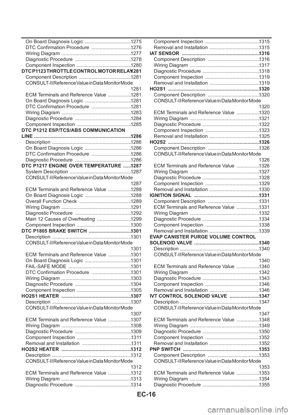
On Board Diagnosis Logic ...................................1275
DTC Confirmation Procedure ..............................1276
Wiring Diagram ....................................................1277
Diagnostic Procedure ..........................................1278
Component Inspection .........................................1280
DTC P1123 THROTTLE CONTROL MOTOR RELAY 1281
Component Description .......................................1281
CONSULT-II Reference Value in Data Monitor Mode
1281
ECM Terminals and Reference Value ..................1281
On Board Diagnosis Logic ...................................1281
DTC Confirmation Procedure ..............................1281
Wiring Diagram ....................................................1283
Diagnostic Procedure ..........................................1284
Component Inspection .........................................1285
DTC P1212 ESP/TCS/ABS COMMUNICATION
LINE ........................................................................1286
Description ...........................................................1286
On Board Diagnosis Logic ...................................1286
DTC Confirmation Procedure ..............................1286
Diagnostic Procedure ..........................................1286
DTC P1217 ENGINE OVER TEMPERATURE .......1287
System Description ..............................................1287
CONSULT-II Reference Value in Data Monitor Mode
1287
ECM Terminals and Reference Value ..................1288
On Board Diagnosis Logic ...................................1288
Overall Function Check .......................................1289
Wiring Diagram ....................................................1291
Diagnostic Procedure ..........................................1292
Main 12 Causes of Overheating ..........................1299
Component Inspection .........................................1300
DTC P1805 BRAKE SWITCH ................................1301
Description ...........................................................1301
CONSULT-II Reference Value in Data Monitor Mode
1301
ECM Terminals and Reference Value ..................1301
On Board Diagnosis Logic ...................................1301
FAIL-SAFE MODE ...............................................1301
DTC Confirmation Procedure ..............................1301
Wiring Diagram ....................................................1303
Diagnostic Procedure ..........................................1304
Component Inspection .........................................1305
HO2S1 HEATER ....................................................1307
Description ...........................................................1307
CONSULT-II Reference Value in Data Monitor Mode
1307
ECM Terminals and Reference Value ..................1307
Wiring Diagram ....................................................1308
Diagnostic Procedure ..........................................1309
Component Inspection .........................................1311
Removal and Installation .....................................1311
HO2S2 HEATER ....................................................1312
Description ...........................................................1312
CONSULT-II Reference Value in Data Monitor Mode
1312
ECM Terminals and Reference Value ..................1312
Wiring Diagram ....................................................1313
Diagnostic Procedure ..........................................1314Component Inspection .........................................1315
Removal and Installation ......................................1315
IAT SENSOR ..........................................................1316
Component Description .......................................1316
Wiring Diagram ....................................................1317
Diagnostic Procedure ........................................... 1318
Component Inspection .........................................1319
Removal and Installation ......................................1319
HO2S1 ....................................................................1320
Component Description .......................................1320
CONSULT-II Reference Value in Data Monitor Mode
1320
ECM Terminals and Reference Value ..................1320
Wiring Diagram ....................................................1321
Diagnostic Procedure ........................................... 1322
Component Inspection .........................................1323
Removal and Installation ......................................1325
HO2S2 ....................................................................1326
Component Description .......................................1326
CONSULT-II Reference Value in Data Monitor Mode
1326
ECM Terminals and Reference Value ..................1326
Wiring Diagram ....................................................1327
Diagnostic Procedure ........................................... 1328
Component Inspection .........................................1329
Removal and Installation ......................................1330
IGNITION SIGNAL .................................................1331
Component Description .......................................1331
ECM Terminals and Reference Value ..................1331
Wiring Diagram ....................................................1332
Diagnostic Procedure ........................................... 1334
Component Inspection .........................................1338
Removal and Installation ......................................1339
EVAP CANISTER PURGE VOLUME CONTROL
SOLENOID VALVE ................................................. 1340
Description ...........................................................1340
CONSULT-II Reference Value in Data Monitor Mode
1340
ECM Terminals and Reference Value ..................1340
Wiring Diagram ....................................................1342
Diagnostic Procedure ........................................... 1343
Component Inspection .........................................1346
Removal and Installation ......................................1346
IVT CONTROL SOLENOID VALVE .......................1347
Description ...........................................................1347
CONSULT-II Reference Value in Data Monitor Mode
1347
ECM Terminals and Reference Value ..................1348
Wiring Diagram ....................................................1349
Diagnostic Procedure ........................................... 1350
Component Inspection .........................................1352
Removal and Installation ......................................1352
PNP SWITCH .........................................................1353
Component Description .......................................1353
CONSULT-II Reference Value in Data Monitor Mode
1353
ECM Terminals and Reference Value ..................1353
Wiring Diagram ....................................................1354
Diagnostic Procedure ........................................... 1355
Page 369 of 3833

EC-19
C
D
E
F
G
H
I
J
K
L
M
ECA ECM Terminals and Reference Value .................1508
On Board Diagnosis Logic ..................................1508
Overall Function Check .......................................1509
Wiring Diagram ...................................................1510
Diagnostic Procedure ..........................................1511
Main 12 Causes of Overheating ..........................1517
Component Inspection ........................................1518
DTC P1233 - P1234 SUCTION CONTROL VALVE 1519
Description ..........................................................1519
CONSULT-II Reference Value in Data Monitor Mode
1519
ECM Terminals and Reference Value .................1519
On Board Diagnosis Logic ..................................1520
DTC Confirmation Procedure ..............................1521
Wiring Diagram ...................................................1522
Diagnostic Procedure ..........................................1523
Component Inspection ........................................1523
Removal and Installation .....................................1524
DTC P1301 - P1304 FUEL INJECTOR ADJUST-
MENT RESISTOR .................................................. 1525
Description ..........................................................1525
ECM Terminals and Reference Value .................1525
On Board Diagnosis Logic ..................................1525
DTC Confirmation Procedure ..............................1525
Wiring Diagram ...................................................1526
Diagnostic Procedure ..........................................1527
Component Inspection ........................................1528
Removal and Installation .....................................1528
DTC P1305 FUEL LEAK .......................................1529
On Board Diagnosis Logic ..................................1529
DTC Confirmation Procedure ..............................1529
Diagnostic Procedure ..........................................1529
Removal and Installation .....................................1529
DTC P1510 ACCELERATOR PEDAL RELEASED
POSITION SWITCH ...............................................1531
Description ..........................................................1531
CONSULT-II Reference Value in Data Monitor Mode
1531
ECM Terminals and Reference Value .................1531
On Board Diagnosis Logic ..................................1532
DTC Confirmation Procedure ..............................1532
Wiring Diagram ...................................................1533
Diagnostic Procedure ..........................................1534
Component Inspection ........................................1535
Removal and Installation .....................................1535
DTC P1606 ECM ...................................................1536
Description ..........................................................1536
On Board Diagnosis Logic ..................................1536
DTC Confirmation Procedure ..............................
1536
Diagnostic Procedure ..........................................1536
DTC P1621 ECM RELAY .......................................1538
ECM Terminals and Reference valve ..................1538
On Board Diagnosis Logic ..................................1538
DTC Confirmation Procedure ..............................1538
Wiring Diagram ...................................................1539
Diagnostic Procedure ..........................................1540
Component Inspection ........................................1541DTC P1660 BATTERY VOLTAGE .........................1542
On Board Diagnosis Logic ...................................1542
DTC Confirmation Procedure ..............................1542
Diagnostic Procedure ..........................................1542
GLOW CONTROL SYSTEM ..................................1544
Description ...........................................................1544
ECM Terminals and Reference Value ..................1544
Wiring Diagram ....................................................1545
Diagnostic Procedure ..........................................1546
Component Inspection .........................................1550
Removal and Installation .....................................1550
EGR VOLUME CONTROL SYSTEM .....................1551
Description ...........................................................1551
CONSULT-II Reference Value in Data Monitor Mode
1551
ECM Terminals and Reference Value ..................1552
Wiring Diagram ....................................................1553
Diagnostic Procedure ..........................................1554
Component Inspection .........................................1556
Removal and Installation .....................................1557
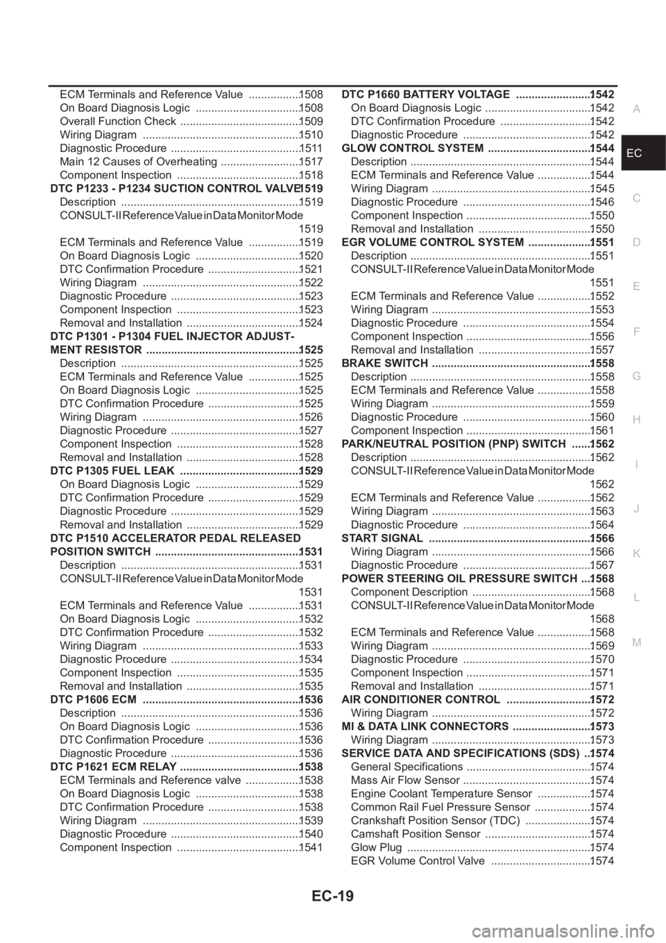
BRAKE SWITCH ....................................................1558
Description ...........................................................1558
ECM Terminals and Reference Value ..................1558
Wiring Diagram ....................................................1559
Diagnostic Procedure ..........................................1560
Component Inspection .........................................1561
PARK/NEUTRAL POSITION (PNP) SWITCH .......1562
Description ...........................................................1562
CONSULT-II Reference Value in Data Monitor Mode
1562
ECM Terminals and Reference Value ..................1562
Wiring Diagram ....................................................1563
Diagnostic Procedure ..........................................1564
START SIGNAL .....................................................1566
Wiring Diagram ....................................................1566
Diagnostic Procedure ..........................................1567
POWER STEERING OIL PRESSURE SWITCH ....1568
Component Description .......................................1568
CONSULT-II Reference Value in Data Monitor Mode
1568
ECM Terminals and Reference Value ..................1568
Wiring Diagram ....................................................1569
Diagnostic Procedure ..........................................1570
Component Inspection .........................................1571
Removal and Installation .....................................1571
AIR CONDITIONER CONTROL ............................1572
Wiring Diagram ....................................................1572
MI & DATA LINK CONNECTORS ..........................1573
Wiring Diagram ....................................................1573
SERVICE DATA AND SPECIFICATIONS (SDS) ...1574
General Specifications ......................................... 1574
Mass Air Flow Sensor ..........................................1574
Engine Coolant Temperature Sensor ..................1574
Common Rail Fuel Pressure Sensor ...................1574
Crankshaft Position Sensor (TDC) ......................1574
Camshaft Position Sensor ...................................1574
Glow Plug ............................................................1574
EGR Volume Control Valve .................................1574
Page 370 of 3833
![NISSAN X-TRAIL 2001 Service Repair Manual EC-20
[QR25(WITH EURO-OBD)]
INDEX FOR DTC
[QR25(WITH EURO-OBD)]INDEX FOR DTCPFP:00024
Alphabetical IndexEBS00M01
Check if the vehicle is a model with Euro-OBD (E-OBD) system or not by the “Type appr NISSAN X-TRAIL 2001 Service Repair Manual EC-20
[QR25(WITH EURO-OBD)]
INDEX FOR DTC
[QR25(WITH EURO-OBD)]INDEX FOR DTCPFP:00024
Alphabetical IndexEBS00M01
Check if the vehicle is a model with Euro-OBD (E-OBD) system or not by the “Type appr](/manual-img/5/57405/w960_57405-369.png)
EC-20
[QR25(WITH EURO-OBD)]
INDEX FOR DTC
[QR25(WITH EURO-OBD)]INDEX FOR DTCPFP:00024
Alphabetical IndexEBS00M01
Check if the vehicle is a model with Euro-OBD (E-OBD) system or not by the “Type approval number” on the
identification plate. Refer to GI-43, "
IDENTIFICATION PLATE" .
NOTE:
If DTC U1000 is displayed with other DTC, first perform the trouble diagnosis for DTC U1000. Refer to
EC-122
.
×: Applicable –: Not applicable
Items
(CONSULT-II screen terms)DTC*
1
TripMI lighting
upReference page
CONSULT-II
GST*
2ECM*3
APP SENSOR P2138 2138 1×EC-373
APP SEN 1/CIRC P2122 2122 1×EC-355
APP SEN 1/CIRC P2123 2123 1×EC-355
APP SEN 2/CIRC P2127 2127 1×EC-361
APP SEN 2/CIRC P2128 2128 1×EC-361
A/T 1ST GR FNCTN P0731 0731 2×AT- 1 3 1
A/T 2ND GR FNCTN P0732 0732 2×AT- 1 3 7
A/T 3RD GR FNCTN P0733 0733 2×AT- 1 4 3
A/T 4TH GR FNCTN P0734 0734 2×AT- 1 4 9
ATF TEMP SEN/CIRC P0710 0710 2×AT- 11 6
BRAKE SW/CIRCUIT P1805 1805 2 –EC-349
CAN COMM CIRCUIT*6U1000
1000*51×EC-122
CKP SEN/CIRCUIT P0335 0335 2×EC-227
CMP SEN/CIRCUIT P0340 0340 2×EC-233
CTP LEARNING P1225 1225 2 –EC-337
CTP LEARNING P1226 1226 2 –EC-339
CYL 1 MISFIRE P0301 0301 2×EC-217
CYL 2 MISFIRE P0302 0302 2×EC-217
CYL 3 MISFIRE P0303 0303 2×EC-217
CYL 4 MISFIRE P0304 0304 2×EC-217
ECM P0605 0605 1 or 2× or –EC-260
ECM BACK UP/CIRC P1065 1065 2×EC-267
ECT SEN/CIRCUIT P0117 0117 1×EC-149
ECT SEN/CIRCUIT P0118 0118 1×EC-149
ENG OVER TEMP P1217 1217 1×EC-323
ENGINE SPEED SIG P0725 0725 2×AT- 1 2 7
ETC ACTR P1121 1121 1 or 2×EC-276
ETC FUNCTION/CIRC P1122 1122 1×EC-278
ETC MOT P1128 1128 1×EC-290
ETC MOT PWR P1124 1124 1×EC-285
ETC MOT PWR P1126 1126 1×EC-285
FUEL SYS-LEAN-B1 P0171 0171 2×EC-200
FUEL SYS-RICH-B1 P0172 0172 2×EC-206
HO2S1 (B1) P0132 0132 2×EC-163
HO2S1 (B1) P0133 0133 2×EC-169
Page 374 of 3833
![NISSAN X-TRAIL 2001 Service Repair Manual EC-24
[QR25(WITH EURO-OBD)]
INDEX FOR DTC
*1: 1st trip DTC No. is the same as DTC No.
*2: These numbers are prescribed by ISO 15031-5.
*3: In Diagnostic Test Mode II (Self-diagnostic results), these n NISSAN X-TRAIL 2001 Service Repair Manual EC-24
[QR25(WITH EURO-OBD)]
INDEX FOR DTC
*1: 1st trip DTC No. is the same as DTC No.
*2: These numbers are prescribed by ISO 15031-5.
*3: In Diagnostic Test Mode II (Self-diagnostic results), these n](/manual-img/5/57405/w960_57405-373.png)
EC-24
[QR25(WITH EURO-OBD)]
INDEX FOR DTC
*1: 1st trip DTC No. is the same as DTC No.
*2: These numbers are prescribed by ISO 15031-5.
*3: In Diagnostic Test Mode II (Self-diagnostic results), these numbers are controlled by NISSAN.
*4: When engine is running.
*5: The trouble shooting for this DTC needs CONSULT-II.
*6: For A/T models.
*7: When the fail-safe operations for both self-diagnoses occur at the same time, the MI illuminates. P1144 1144 HO2S1 (B1) 2×EC-301
P1146 1146 HO2S2 (B1) 2×EC-307
P1147 1147 HO2S2 (B1) 2×EC-315
P1217 1217 ENG OVER TEMP 1×EC-323
P1225 1225 CTP LEARNING 2 –EC-337
P1226 1226 CTP LEARNING 2 –EC-339
P1229 1229 SENSOR POWER/CIRC 1×EC-341
P1610 - P1615 1610 - 1615 NATS MALFUNCTION 2 –EC-58
P1705 1705 TP SEN/CIRC A/T 1×AT-180
P1706 1706 P-N POS SW/CIRCUIT 2×EC-345
P1760 1760 O/R CLTCH SOL/CIRC 2×AT-185
P1805 1805 BRAKE SW/CIRCUIT 2 –EC-349
P2122 2122 APP SEN 1/CIRC 1×EC-355
P2123 2123 APP SEN 1/CIRC 1×EC-355
P2127 2127 APP SEN 2/CIRC 1×EC-361
P2128 2128 APP SEN 2/CIRC 1×EC-361
P2135 2135 TP SENSOR 1×EC-367
P2138 2138 APP SENSOR 1×EC-373
DTC*1
Items
(CONSULT-II screen terms)TripMI lighting
upReference page
CONSULT-II
GST*
2ECM*3