2001 NISSAN X-TRAIL brake sensor
[x] Cancel search: brake sensorPage 1784 of 3833
![NISSAN X-TRAIL 2001 Service Repair Manual EC-1434
[YD]
TROUBLE DIAGNOSIS
ACCEL POS SEN [V]××
●The accelerator pedal position
sensor 1 signal voltage is dis-
played.
ACCEL SEN 2 [V]××
●The accelerator pedal position
sensor 2 signal v NISSAN X-TRAIL 2001 Service Repair Manual EC-1434
[YD]
TROUBLE DIAGNOSIS
ACCEL POS SEN [V]××
●The accelerator pedal position
sensor 1 signal voltage is dis-
played.
ACCEL SEN 2 [V]××
●The accelerator pedal position
sensor 2 signal v](/manual-img/5/57405/w960_57405-1783.png)
EC-1434
[YD]
TROUBLE DIAGNOSIS
ACCEL POS SEN [V]××
●The accelerator pedal position
sensor 1 signal voltage is dis-
played.
ACCEL SEN 2 [V]××
●The accelerator pedal position
sensor 2 signal voltage is dis-
played.
OFF ACCEL SW [ON/OFF]××
●indicates [ON/OFF] condition
from the accelerator pedal
released position switch signal.
ACT CR PRESS [MPa]××
●The common rail fuel pressure
(determined by the signal volt-
age of the common rail fuel
pressure sensor) is displayed.
BATTERY VOLT [V]××
●The power supply voltage of
ECM is displayed.
P/N POSI SW [ON/OFF]××
●Indicates [ON/OFF] condition
from the park/neutral position
switch signal.
START SIGNAL [ON/OFF]××
●indicates [ON/OFF] condition
from the starter signal.
PW/ST SIGNAL [ON/OFF]×
●indicates [ON/OFF] condition
from the power steering oil pres-
sure switch signal.
BRAKE SW [ON/OFF]××
●indicates [ON/OFF] condition
from the stop lamp switch sig-
nal.
IGN SW [ON/OFF]××
●Indicates [ON/OFF] condition
from ignition switch signal.
MAS AIR/FL SE [V]××
●The signal voltage of the mass
air flow sensor is displayed.
SUCTION CV [°CA]×
●Indicates [°CA] of suction con-
trol valve operating angle.
MAIN INJ WID [msec]×
●Indicates the actual fuel injec-
tion pulse width compensated
by ECM according to the input
signals.
GLOW RLY [ON/OFF]×
●The glow relay control condition
(determined by ECM according
to the input signal) is displayed.
COOLING FAN
[LOW/HI/OFF]×
●Indicates the control condition of
the cooling fans (determined by
ECM according to the input sig-
nal).
LOW ... Operates at low speed.
HI ... Operates at high speed.
OFF ... Stopped
EGR VOL CON/V [step]×
●Indicates the EGR volume con-
tro l value co mp ute d by the ECM
according to the input signals.
●The opening becomes larger as
the value increases. MONITOR ITEMECM
INPUT
SIG-
NALMAIN
SIG-
NALSCAN
DIAG
SUP-
PORT
MNTRCONDITION SPECIFICATION
Page 2080 of 3833
AT-2
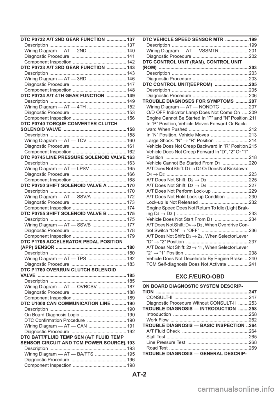
DTC P0732 A/T 2ND GEAR FUNCTION ................137
Description ............................................................137
Wiring Diagram — AT — 2ND ..............................140
Diagnostic Procedure ...........................................141
Component Inspection ..........................................142
DTC P0733 A/T 3RD GEAR FUNCTION ................143
Description ............................................................143
Wiring Diagram — AT — 3RD ..............................146
Diagnostic Procedure ...........................................147
Component Inspection ..........................................148
DTC P0734 A/T 4TH GEAR FUNCTION ................149
Description ............................................................149
Wiring Diagram — AT — 4TH ...............................152
Diagnostic Procedure ...........................................153
Component Inspection ..........................................156
DTC P0740 TORQUE CONVERTER CLUTCH
SOLENOID VALVE .................................................158
Description ............................................................158
Wiring Diagram — AT — TCV ..............................160
Diagnostic Procedure ...........................................161
Component Inspection ..........................................162
DTC P0745 LINE PRESSURE SOLENOID VALVE .163
Description ............................................................163
Wiring Diagram — AT — LPSV ............................165
Diagnostic Procedure ...........................................166
Component Inspection ..........................................168
DTC P0750 SHIFT SOLENOID VALVE A ...............170
Description ............................................................170
Wiring Diagram — AT — SSV/A ...........................172
Diagnostic Procedure ...........................................173
Component Inspection ..........................................174
DTC P0755 SHIFT SOLENOID VALVE B ...............175
Description ............................................................175
Wiring Diagram — AT — SSV/B ...........................177
Diagnostic Procedure ...........................................178
Component Inspection ..........................................179
DTC P1705 ACCELERATOR PEDAL POSITION
(APP) SENSOR .......................................................180
Description ............................................................180
Wiring Diagram — AT — TPS ..............................182
Diagnostic Procedure ...........................................183
DTC P1760 OVERRUN CLUTCH SOLENOID
VALVE .....................................................................185
Description ............................................................185
Wiring Diagram — AT — OVRCSV ......................187
Diagnostic Procedure ...........................................188
Component Inspection ..........................................189
DTC U1000 CAN COMMUNICATION LINE ...........
.190
Description ............................................................190
On Board Diagnosis Logic ....................................190
DTC Confirmation Procedure ...............................190
Wiring Diagram — AT — CAN ..............................191
Diagnostic Procedure ...........................................192
DTC BATT/FLUID TEMP SEN (A/T FLUID TEMP
SENSOR CIRCUIT AND TCM POWER SOURCE) .193
Description ............................................................193
Wiring Diagram — AT — BA/FTS .........................195
Diagnostic Procedure ...........................................196
Component Inspection ..........................................198DTC VEHICLE SPEED SENSOR MTR ...................199
Description ............................................................199
Wiring Diagram — AT — VSSMTR .......................201
Diagnostic Procedure ............................................202
DTC CONTROL UNIT (RAM), CONTROL UNIT
(ROM) ......................................................................203
Description ............................................................203
Diagnostic Procedure ............................................203
DTC CONTROL UNIT(EEPROM) ...........................205
Description ............................................................205
Diagnostic Procedure ............................................206
TROUBLE DIAGNOSES FOR SYMPTOMS ...........207
Wiring Diagram — AT — NONDTC ......................207
O/D OFF Indicator Lamp Does Not Come On ......209
Engine Cannot Be Started In “P” and “N” Position .211
In “P” Position, Vehicle Moves Forward Or Back-
ward When Pushed ...............................................212
In “N” Position, Vehicle Moves ..............................213
Large Shock. “N” → “R” Position ..........................214
Vehicle Does Not Creep Backward In “R” Position .215
Vehicle Does Not Creep Forward In “D”, “2” Or “1”
Position .................................................................218
Vehicle Cannot Be Started From D
1 .....................220
A/T Does Not Shift: D
1→ D2 Or Does Not Kickdown:
D
4→ D2 ...............................................................
.223
A/T Does Not Shift: D
2→ D3 ................................225
A/T Does Not Shift: D
3→ D4 ................................227
A/T Does Not Perform Lock-up .............................229
A/T Does Not Hold Lock-up Condition ..................230
Lock-up Is Not Released .......................................232
Engine Speed Does Not Return To Idle (Light Brak-
ing D
4→ D3 ) ........................................................233
Vehicle Does Not Start From D
1 ...........................234
A / T D o e s N o t S h i f t : D
4→ D3 , W h e n O v e r d r i v e C o n -
trol Switch “ON” → “OFF” .....................................236
A/T Does Not Shift: D
3→ 22 , W h e n S e l e c t o r L e v e r
“D” → “2” Position .................................................237
A/T Does Not Shift: 2
2→ 11 , When Selector Lever
“2” → “1” Position ..................................................238
Vehicle Does Not Decelerate By Engine Brake ....240
TCM Self-diagnosis Does Not Activate .................241
EXC.F/EURO-OBD
ON BOARD DIAGNOSTIC SYSTEM DESCRIP-
TION ........................................................................247
CONSULT-II ..........................................................247
Diagnostic Procedure Without CONSULT-II .........253
TROUBLE DIAGNOSIS — INTRODUCTION .........258
Introduction ...........................................................258
Work Flow .............................................................262
TROUBLE DIAGNOSIS — BASIC INSPECTION ...264
A/T Fluid Check ....................................................264
Stall Test ................................................................265
Line Pressure Test ................................................268
Road Test ..............................................................269
TROUBLE DIAGNOSIS — GENERAL DESCRIP-
Page 2081 of 3833
AT-3
D
E
F
G
H
I
J
K
L
MA
B
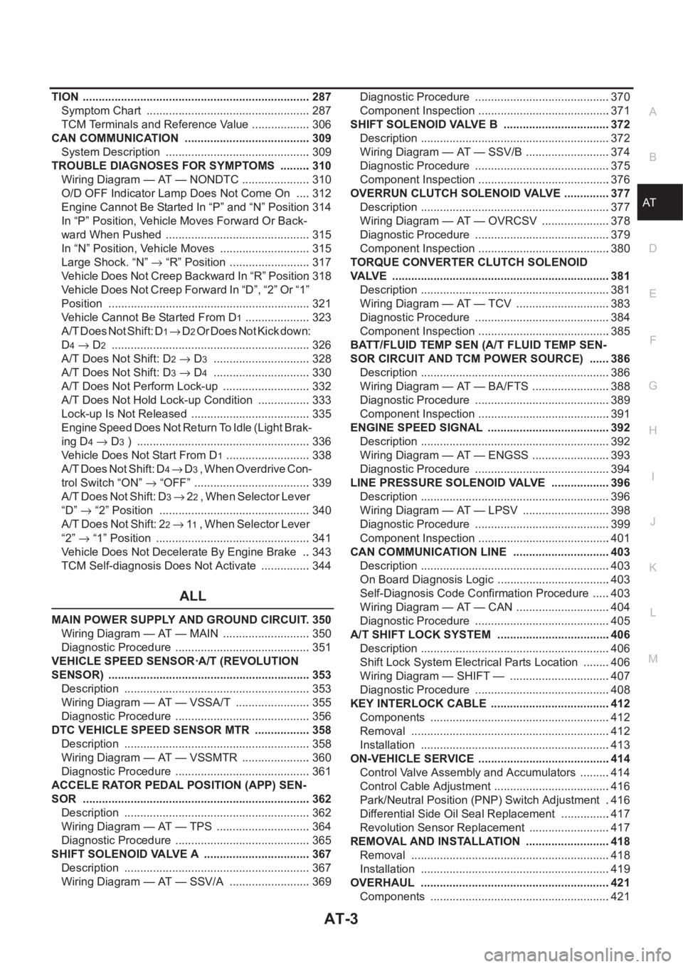
AT TION ........................................................................ 287
Symptom Chart .................................................... 287
TCM Terminals and Reference Value ................... 306
CAN COMMUNICATION ........................................ 309
System Description .............................................. 309
TROUBLE DIAGNOSES FOR SYMPTOMS .......... 310
Wiring Diagram — AT — NONDTC ...................... 310
O/D OFF Indicator Lamp Does Not Come On ..... 312
Engine Cannot Be Started In “P” and “N” Position . 314
In “P” Position, Vehicle Moves Forward Or Back-
ward When Pushed .............................................. 315
In “N” Position, Vehicle Moves ............................. 315
Large Shock. “N” → “R” Position .......................... 317
Vehicle Does Not Creep Backward In “R” Position . 318
Vehicle Does Not Creep Forward In “D”, “2” Or “1”
Position ................................................................ 321
Vehicle Cannot Be Started From D
1 ..................... 323
A/T Does Not Shift: D
1→ D2 Or Does Not Kick down:
D
4→ D2 ............................................................... 326
A/T Does Not Shift: D
2→ D3 ............................... 328
A/T Does Not Shift: D
3→ D4 ............................... 330
A/T Does Not Perform Lock-up ............................ 332
A/T Does Not Hold Lock-up Condition ................. 333
Lock-up Is Not Released ...................................... 335
Engine Speed Does Not Return To Idle (Light Brak-
ing D
4→ D3 ) ....................................................... 336
Vehicle Does Not Start From D
1 ........................... 338
A/T Does Not Shift: D
4→ D3 , When Overdrive Con-
trol Switch “ON” → “OFF” ..................................... 339
A/T Does Not Shift: D
3→ 22 , W h e n S e l e c t o r L e v e r
“D”→ “2” Position ................................................ 340
A/T Does Not Shift: 2
2→ 11 , W h e n S e l e c t o r L e v e r
“2” → “1” Position ................................................. 341
Vehicle Does Not Decelerate By Engine Brake ... 343
TCM Self-diagnosis Does Not Activate ................ 344
ALL
MAIN POWER SUPPLY AND GROUND CIRCUIT . 350
Wiring Diagram — AT — MAIN ............................ 350
Diagnostic Procedure ........................................... 351
VEHICLE SPEED SENSOR·A/T (REVOLUTION
SENSOR) ................................................................ 353
Description ........................................................... 353
Wiring Diagram — AT — VSSA/T ........................ 355
Diagnostic Procedure ........................................... 356
DTC VEHICLE SPEED SENSOR MTR .................. 358
Description ........................................................... 358
Wiring Diagram — AT — VSSMTR ...................... 360
Diagnostic Procedure ........................................... 361
ACCELE RATOR PEDAL POSITION (APP) SEN-
SOR ........................................................................ 362
Description ........................................................... 362
Wiring Diagram — AT — TPS .............................. 364
Diagnostic Procedure ........................................... 365
SHIFT SOLENOID VALVE A .................................. 367
Description ........................................................... 367
Wiring Diagram — AT — SSV/A .......................... 369Diagnostic Procedure ...........................................370
Component Inspection ..........................................371
SHIFT SOLENOID VALVE B ..................................372
Description ............................................................372
Wiring Diagram — AT — SSV/B ...........................374
Diagnostic Procedure ...........................................375
Component Inspection ..........................................376
OVERRUN CLUTCH SOLENOID VALVE ...............377
Description ............................................................377
Wiring Diagram — AT — OVRCSV ......................378
Diagnostic Procedure ...........................................379
Component Inspection ..........................................380
TORQUE CONVERTER CLUTCH SOLENOID
VALVE .....................................................................381
Description ............................................................381
Wiring Diagram — AT — TCV ..............................383
Diagnostic Procedure ...........................................384
Component Inspection ..........................................385
BATT/FLUID TEMP SEN (A/T FLUID TEMP SEN-
SOR CIRCUIT AND TCM POWER SOURCE) .......386
Description ............................................................386
Wiring Diagram — AT — BA/FTS .........................388
Diagnostic Procedure ...........................................389
Component Inspection ..........................................391
ENGINE SPEED SIGNAL .......................................392
Description ............................................................392
Wiring Diagram — AT — ENGSS .........................393
Diagnostic Procedure ...........................................394
LINE PRESSURE SOLENOID VALVE ..................
.396
Description ............................................................396
Wiring Diagram — AT — LPSV ............................398
Diagnostic Procedure ...........................................399
Component Inspection ..........................................401
CAN COMMUNICATION LINE ...............................403
Description ............................................................403
On Board Diagnosis Logic ....................................403
Self-Diagnosis Code Confirmation Procedure ......403
Wiring Diagram — AT — CAN ..............................404
Diagnostic Procedure ...........................................405
A/T SHIFT LOCK SYSTEM ....................................406
Description ............................................................406
Shift Lock System Electrical Parts Location .........406
Wiring Diagram — SHIFT — ................................407
Diagnostic Procedure ...........................................408
KEY INTERLOCK CABLE ......................................412
Components .........................................................412
Removal ...............................................................412
Installation ............................................................413
ON-VEHICLE SERVICE ..........................................414
Control Valve Assembly and Accumulators ..........414
Control Cable Adjustment .....................................416
Park/Neutral Position (PNP) Switch Adjustment ..416
Differential Side Oil Seal Replacement ................417
Revolution Sensor Replacement ..........................417
REMOVAL AND INSTALLATION ...........................418
Removal ...............................................................418
Installation ............................................................419
OVERHAUL ............................................................421
Components .........................................................421
Page 2082 of 3833
AT-4
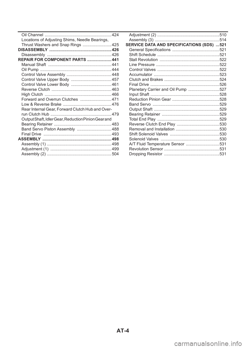
Oil Channel ...........................................................424
Locations of Adjusting Shims, Needle Bearings,
Thrust Washers and Snap Rings ..........................425
DISASSEMBLY .......................................................426
Disassembly .........................................................426
REPAIR FOR COMPONENT PARTS ......................441
Manual Shaft ........................................................441
Oil Pump ...............................................................444
Control Valve Assembly ........................................448
Control Valve Upper Body ....................................457
Control Valve Lower Body ....................................461
Reverse Clutch .....................................................463
High Clutch ...........................................................466
Forward and Overrun Clutches ............................471
Low & Reverse Brake ...........................................476
Rear Internal Gear, Forward Clutch Hub and Over-
run Clutch Hub ......................................................479
Output Shaft, Idler Gear, Reduction Pinion Gear and
Bearing Retainer ...................................................483
Band Servo Piston Assembly ...............................488
Final Drive ............................................................493
ASSEMBLY .............................................................498
Assembly (1) .........................................................498
Adjustment (1) ......................................................499
Assembly (2) .........................................................504Adjustment (2) .......................................................510
Assembly (3) .........................................................514
SERVICE DATA AND SPECIFICATIONS (SDS) ....521
General Specifications ......................................... .521
Shift Schedule .......................................................521
Stall Revolution .....................................................522
Line Pressure ........................................................522
Control Valves .......................................................522
Accumulator ..........................................................523
Clutch and Brakes .................................................524
Final Drive .............................................................526
Planetary Carrier and Oil Pump ............................527
Input Shaft .............................................................528
Reduction Pinion Gear ..........................................528
Band Servo ...........................................................529
Output Shaft ..................................................
........529
Bearing Retainer ...................................................529
Total End Play .......................................................529
Reverse Clutch End Play ......................................530
Removal and Installation .......................................530
Shift Solenoid Valves ............................................530
Solenoid Valves ....................................................530
A/T Fluid Temperature Sensor ..............................531
Revolution Sensor .................................................531
Dropping Resistor .................................................531
Page 2107 of 3833
OVERALL SYSTEM
AT-29
D
E
F
G
H
I
J
K
L
MA
B
AT
TCM FUNCTION
The function of the TCM is to:
●Receive input signals sent from various switches and sensors.
●Determine required line pressure, shifting point, lock-up operation, and engine brake operation.
●Send required output signals to the respective solenoids.
INPUT/OUTPUT SIGNAL OF TCM
Control MechanismECS004QF
LINE PRESSURE CONTROL
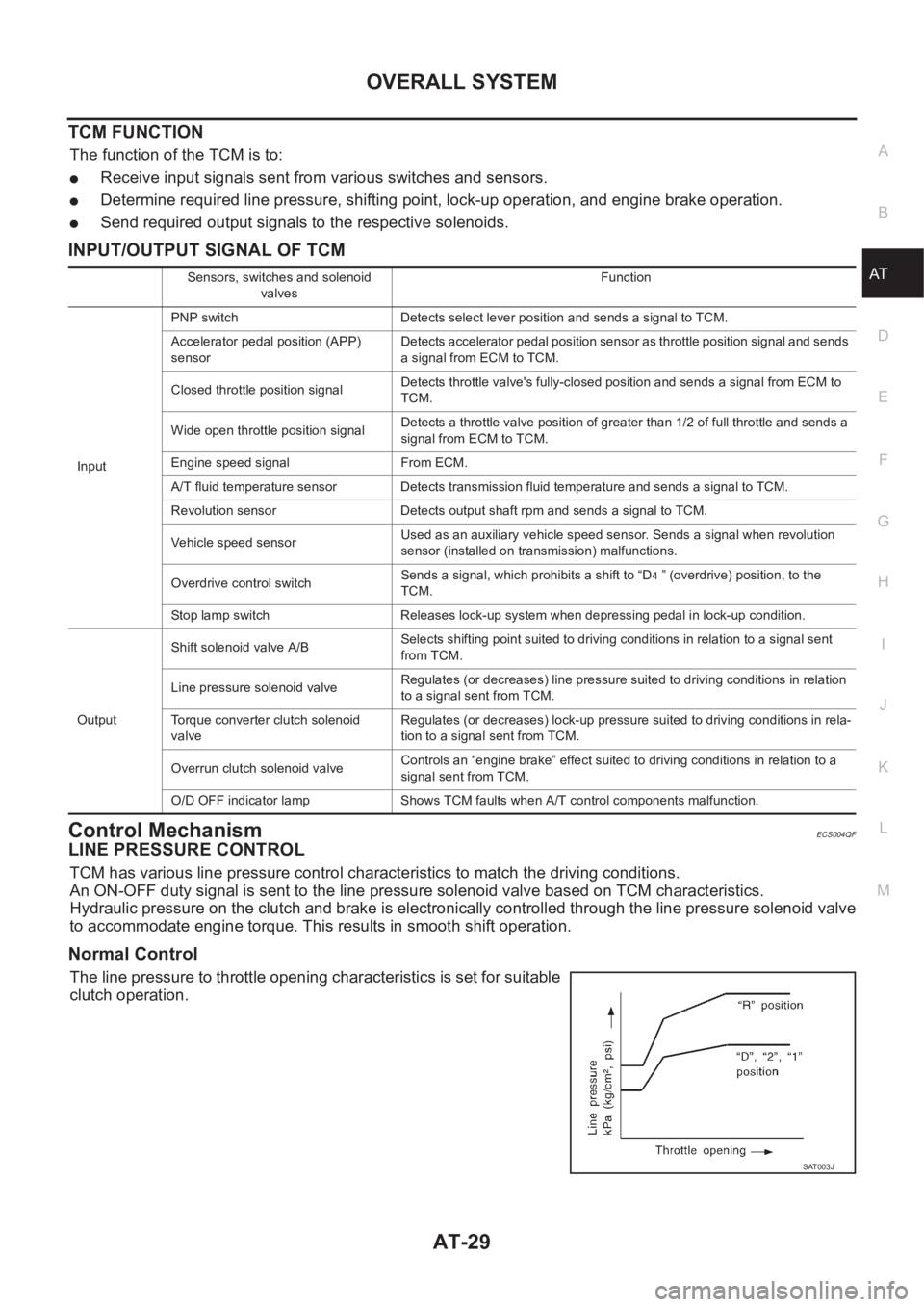
TCM has various line pressure control characteristics to match the driving conditions.
An ON-OFF duty signal is sent to the line pressure solenoid valve based on TCM characteristics.
Hydraulic pressure on the clutch and brake is electronically controlled through the line pressure solenoid valve
to accommodate engine torque. This results in smooth shift operation.
Normal Control
The line pressure to throttle opening characteristics is set for suitable
clutch operation.
Sensors, switches and solenoid
valvesFunction
InputPNP switch Detects select lever position and sends a signal to TCM.
Accelerator pedal position (APP)
sensorDetects accelerator pedal position sensor as throttle position signal and sends
a signal from ECM to TCM.
Closed throttle position signalDetects throttle valve's fully-closed position and sends a signal from ECM to
TCM.
Wide open throttle position signalDetects a throttle valve position of greater than 1/2 of full throttle and sends a
signal from ECM to TCM.
Engine speed signal From ECM.
A/T fluid temperature sensor Detects transmission fluid temperature and sends a signal to TCM.
Revolution sensor Detects output shaft rpm and sends a signal to TCM.
Vehicle speed sensorUsed as an auxiliary vehicle speed sensor. Sends a signal when revolution
sensor (installed on transmission) malfunctions.
Overdrive control switchSends a signal, which prohibits a shift to “D
4 ” (overdrive) position, to the
TCM.
Stop lamp switch Releases lock-up system when depressing pedal in lock-up condition.
OutputShift solenoid valve A/BSelects shifting point suited to driving conditions in relation to a signal sent
from TCM.
Line pressure solenoid valveRegulates (or decreases) line pressure suited to driving conditions in relation
to a signal sent from TCM.
Torque converter clutch solenoid
valveRegulates (or decreases) lock-up pressure suited to driving conditions in rela-
tion to a signal sent from TCM.
Overrun clutch solenoid valveControls an “engine brake” effect suited to driving conditions in relation to a
signal sent from TCM.
O/D OFF indicator lamp Shows TCM faults when A/T control components malfunction.
SAT003J
Page 2108 of 3833
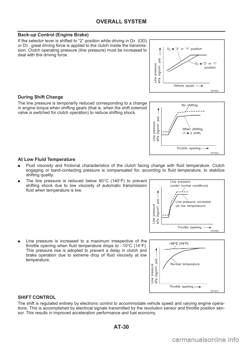
AT-30
OVERALL SYSTEM
Back-up Control (Engine Brake)
If the selector lever is shifted to “2” position while driving in D4 (OD)
or D
3 , great driving force is applied to the clutch inside the transmis-
sion. Clutch operating pressure (line pressure) must be increased to
deal with this driving force.
During Shift Change
The line pressure is temporarily reduced corresponding to a change
in engine torque when shifting gears (that is, when the shift solenoid
valve is switched for clutch operation) to reduce shifting shock.
At Low Fluid Temperature
●Fluid viscosity and frictional characteristics of the clutch facing change with fluid temperature. Clutch
engaging or band-contacting pressure is compensated for, according to fluid temperature, to stabilize
shifting quality.
●The line pressure is reduced below 60°C (140°F) to prevent
shifting shock due to low viscosity of automatic transmission
fluid when temperature is low.
●Line pressure is increased to a maximum irrespective of the
throttle opening when fluid temperature drops to −10°C (14°F).
This pressure rise is adopted to prevent a delay in clutch and
brake operation due to extreme drop of fluid viscosity at low
temperature.
SHIFT CONTROL
The shift is regulated entirely by electronic control to accommodate vehicle speed and varying engine opera-
tions. This is accomplished by electrical signals transmitted by the revolution sensor and throttle position sen-
sor. This results in improved acceleration performance and fuel economy.
SAT004J
SAT005J
SAT006J
SAT007J
Page 2136 of 3833
![NISSAN X-TRAIL 2001 Service Repair Manual AT-58
[EURO-OBD]
TROUBLE DIAGNOSIS — INTRODUCTION
Diagnostic Worksheet
1.❏ Read the Fail-safe and listen to customer complaints.AT-57, "Infor-
mation from
Customer"
2.❏ CHECK A/T FLUIDA NISSAN X-TRAIL 2001 Service Repair Manual AT-58
[EURO-OBD]
TROUBLE DIAGNOSIS — INTRODUCTION
Diagnostic Worksheet
1.❏ Read the Fail-safe and listen to customer complaints.AT-57, "Infor-
mation from
Customer"
2.❏ CHECK A/T FLUIDA](/manual-img/5/57405/w960_57405-2135.png)
AT-58
[EURO-OBD]
TROUBLE DIAGNOSIS — INTRODUCTION
Diagnostic Worksheet
1.❏ Read the Fail-safe and listen to customer complaints.AT-57, "Infor-
mation from
Customer"
2.❏ CHECK A/T FLUIDAT-63, "A/T
Fluid Check"❏ Leakage (Follow specified procedure)
❏ Fluid condition
❏ Fluid level
3.❏ Perform STALL TEST and LINE PRESSURE TEST.AT-64, "
Stall
Te s t",AT- 6 7 ,
"Line Pres-
sure Test"
❏ Stall test — Mark possible damaged components/others.
❏ Torque converter one-way clutch
❏ Reverse clutch
❏ Forward clutch
❏ Overrun clutch
❏ Forward one-way clutch❏ Low & reverse brake
❏ Low one-way clutch
❏ Engine
❏ Line pressure is low
❏ Clutches and brakes except high clutch and
brake band are OK
❏ Line Pressure test — Suspected parts:
4.❏ Perform all ROAD TEST and mark required procedures.AT-68, "
Road
Te s t"
4-1. Check before engine is started.AT-70, "1.
CHECK
BEFORE
ENGINE IS
STARTED"
❏ O/D OFF Indicator Lamp Does Not Come On, AT-209, "O/D OFF Indicator Lamp Does Not Come On" .
❏ SELF-DIAGNOSTIC PROCEDURE/DIAGNOSTIC TROUBLE CODE (DTC) CONFIRMATION PRO-
CEDURE. — Mark detected items.
❏ PNP switch, AT-110, "
DTC P0705 PARK/NEUTRAL POSITION (PNP) SWITCH" .
❏ A/T fluid temperature sensor, AT-116, "
DTC P0710 A/T FLUID TEMPERATURE SENSOR CIR-
CUIT" .
❏ Vehicle speed sensor·A/T (Revolution sensor), AT-122, "
DTC P0720 VEHICLE SPEED SEN-
SOR·A/T (REVOLUTION SENSOR)" .
❏ Engine speed signal, AT-127, "
DTC P0725 ENGINE SPEED SIGNAL" .
❏ Torque converter clutch solenoid valve, AT-158, "
DTC P0740 TORQUE CONVERTER CLUTCH
SOLENOID VALVE" .
❏ Line pressure solenoid valve, AT-163, "
DTC P0745 LINE PRESSURE SOLENOID VALVE" .
❏ Shift solenoid valve A, AT-170, "
DTC P0750 SHIFT SOLENOID VALVE A" .
❏ Shift solenoid valve B, AT-175, "
DTC P0755 SHIFT SOLENOID VALVE B" .
❏ Accelerator pedal position (App) sensor, AT- 1 8 0 , "
DTC P1705 ACCELERATOR PEDAL POSITION
(APP) SENSOR" .
❏ Overrun clutch solenoid valve, AT-185, "
DTC P1760 OVERRUN CLUTCH SOLENOID VALVE" .
❏ PNP & overdrive control switches, and throttle position sensor, AT- 2 4 1 , "
TCM Self-diagnosis Does
Not Activate" .
❏ Batt/fluid temp sen (A/T fluid temperature sensor and TCM power source), AT-193, "
DTC BATT/
FLUID TEMP SEN (A/T FLUID TEMP SENSOR CIRCUIT AND TCM POWER SOURCE)" .
❏ Vehicle speed sensor·MTR, AT-199, "
DTC VEHICLE SPEED SENSOR MTR" .
❏ CAN communication line, AT-190, "
DTC U1000 CAN COMMUNICATION LINE" .
❏ Control unit (RAM), control unit (ROM), AT- 2 0 3 , "
DTC CONTROL UNIT (RAM), CONTROL UNIT
(ROM)" .
❏ Control unit (EEP ROM), AT- 2 0 5 , "
DTC CONTROL UNIT(EEPROM)" .
❏ Battery
❏ Others
4-2. Check at idleAT-71, "
2.
CHECK AT
IDLE"❏ Engine Cannot Be Started In “P” And “N” Position, AT- 2 11 , "Engine Cannot Be Started In “P” and “N”
Position" .
❏ In “P” Position, Vehicle Moves Forward Or Backward When Pushed, AT-212, "
In “P” Position, Vehicle
Moves Forward Or Backward When Pushed" .
❏ In “N” Position, Vehicle Moves, AT-213, "
In “N” Position, Vehicle Moves" .
❏ Large Shock. “N” → “R” Position, AT-214, "
Large Shock. “N”→“R” Position" .
❏ Vehicle Does Not Creep Backward In “R” Position, AT-215, "
Vehicle Does Not Creep Backward In “R”
Position" .
❏ Vehicle Does Not Creep Forward In “D”, “2” Or “1” Position, AT- 2 1 8 , "
Vehicle Does Not Creep Forward
In “D”,“2” Or “1” Position" .
Page 2137 of 3833
![NISSAN X-TRAIL 2001 Service Repair Manual TROUBLE DIAGNOSIS — INTRODUCTION
AT-59
[EURO-OBD]
D
E
F
G
H
I
J
K
L
MA
B
AT
4. 4-3. Cruise testAT- 7 4 , "3.
CRUISE
TEST"
AT- 7 8 ,
"Cruise Test
— Part 1"
Part-1
❏ Vehicle NISSAN X-TRAIL 2001 Service Repair Manual TROUBLE DIAGNOSIS — INTRODUCTION
AT-59
[EURO-OBD]
D
E
F
G
H
I
J
K
L
MA
B
AT
4. 4-3. Cruise testAT- 7 4 , "3.
CRUISE
TEST"
AT- 7 8 ,
"Cruise Test
— Part 1"
Part-1
❏ Vehicle](/manual-img/5/57405/w960_57405-2136.png)
TROUBLE DIAGNOSIS — INTRODUCTION
AT-59
[EURO-OBD]
D
E
F
G
H
I
J
K
L
MA
B
AT
4. 4-3. Cruise testAT- 7 4 , "3.
CRUISE
TEST"
AT- 7 8 ,
"Cruise Test
— Part 1"
Part-1
❏ Vehicle Cannot Be Started From D
1 , AT- 2 2 0 , "Vehicle Cannot Be Started From D1" .
❏ A/T Does Not Shift: D
1→ D2 Or Does Not Kickdown: D4→ D2 , AT-223, "A/T Does Not Shift: D1→
D2 Or Does Not Kickdown: D4→ D2" .
❏ A/T Does Not Shift: D
2→ D3 , AT- 2 2 5 , "A/T Does Not Shift: D2→ D3" .
❏ A/T Does Not Shift: D
3→ D4 , AT- 2 2 7 , "A/T Does Not Shift: D3→ D4" .
❏ A/T Does Not Perform Lock-up, AT-229, "
A/T Does Not Perform Lock-up" .
❏ A/T Does Not Hold Lock-up Condition, AT-230, "
A/T Does Not Hold Lock-up Condition" .
❏ Lock-up Is Not Released, AT-232, "
Lock-up Is Not Released" .
❏ Engine Speed Does Not Return To Idle (Light Braking D
4→ D3 ), AT-233, "Engine Speed Does Not
Return To Idle (Light Braking D4→ D3 )" .
Part-2AT- 8 1 ,
"Cruise Test
— Part 2"❏ Vehicle Does Not Start From D1 , AT- 2 3 4 , "Vehicle Does Not Start From D1" .
❏ A/T Does Not Shift: D
1→ D2 Or Does Not Kickdown: D4→ D2 , AT-223, "A/T Does Not Shift: D1→
D2 Or Does Not Kickdown: D4→ D2" .
❏ A/T Does Not Shift: D
2→ D3 , AT- 2 2 5 , "A/T Does Not Shift: D2→ D3" .
❏ A/T Does Not Shift: D
3→ D4 , AT- 2 2 7 , "A/T Does Not Shift: D3→ D4" .
Part-3AT- 8 3 ,
"Cruise Test
— Part 3"❏ A/T Does Not Shift: D4→ D3 When Overdrive Control Switch “ON” → “OFF”, AT-236, "A/T Does Not
Shift: D4→ D3 , When Overdrive Control Switch “ON”→“OFF”" .
❏ Engine Speed Does Not Return To Idle (Engine Brake In D
3 ), AT-233, "Engine Speed Does Not Return
To Idle (Light Braking D4→ D3 )" .
❏ A/T Does Not Shift: D
3→ 22 , When Selector Lever “D” → “2” Position, AT- 2 3 7 , "A/T Does Not Shift:
D3→ 22 , When Selector Lever “D”→“2” Position" .
❏ Engine Speed Does Not Return To Idle (Engine Brake In 2
2 ), AT- 2 3 3 , "Engine Speed Does Not Return
To Idle (Light Braking D4→ D3 )" .
❏ A/T Does Not Shift: 2
2→ 11 , When Selector Lever “2” → “1” Position, AT-238, "A/T Does Not Shift: 22
→ 11 , When Selector Lever “2”→“1” Position" .
❏ Vehicle Does Not Decelerate By Engine Brake, AT- 2 4 0 , "
Vehicle Does Not Decelerate By Engine
Brake" .
❏ TCM Self-diagnosis Does Not Activate (PNP & Overdrive control switches, and throttle position sensor
circuit checks), AT-241, "
TCM Self-diagnosis Does Not Activate" .
❏ SELF-DIAGNOSTIC PROCEDURE/DIAGNOSTIC TROUBLE CODE (DTC) CONFIRMATION PRO-
CEDURE — Mark detected items.
❏ PNP switch, AT- 11 0 , "
DTC P0705 PARK/NEUTRAL POSITION (PNP) SWITCH" .
❏ A/T fluid temperature sensor, AT- 11 6 , "
DTC P0710 A/T FLUID TEMPERATURE SENSOR CIR-
CUIT" .
❏ Vehicle speed sensor·A/T (Revolution sensor), AT- 1 2 2 , "
DTC P0720 VEHICLE SPEED SEN-
SOR·A/T (REVOLUTION SENSOR)" .
❏ Engine speed signal, AT- 1 2 7 , "
DTC P0725 ENGINE SPEED SIGNAL" .
❏ Torque converter clutch solenoid valve, AT-158, "
DTC P0740 TORQUE CONVERTER CLUTCH
SOLENOID VALVE" .
❏ Line pressure solenoid valve, AT-163, "
DTC P0745 LINE PRESSURE SOLENOID VALVE" .
❏ Shift solenoid valve A, AT- 1 7 0 , "
DTC P0750 SHIFT SOLENOID VALVE A" .
❏ Shift solenoid valve B, AT- 1 7 5 , "
DTC P0755 SHIFT SOLENOID VALVE B" .
❏ Accelerator pedal position (App) sensor, AT-180, "
DTC P1705 ACCELERATOR PEDAL POSITION
(APP) SENSOR" .
❏ Overrun clutch solenoid valve, AT- 1 8 5 , "
DTC P1760 OVERRUN CLUTCH SOLENOID VALVE" .
❏ PNP & overdrive control switches, and throttle position sensor, AT-241, "
TCM Self-diagnosis Does
Not Activate" .
❏ A/T fluid temperature sensor and TCM power source, AT-193, "
DTC BATT/FLUID TEMP SEN (A/T
FLUID TEMP SENSOR CIRCUIT AND TCM POWER SOURCE)" .
❏ Vehicle speed sensor·MTR, AT-199, "
DTC VEHICLE SPEED SENSOR MTR" .
❏ CAN communication line, AT- 1 9 0 , "
DTC U1000 CAN COMMUNICATION LINE" .
❏ Control unit (RAM), control unit (ROM), AT-203, "
DTC CONTROL UNIT (RAM), CONTROL UNIT
(ROM)" .
❏ Control unit (EEP ROM), AT-205, "
DTC CONTROL UNIT(EEPROM)" .
❏ Battery
❏ Others