2001 NISSAN X-TRAIL timing belt
[x] Cancel search: timing beltPage 52 of 3833
EM-2
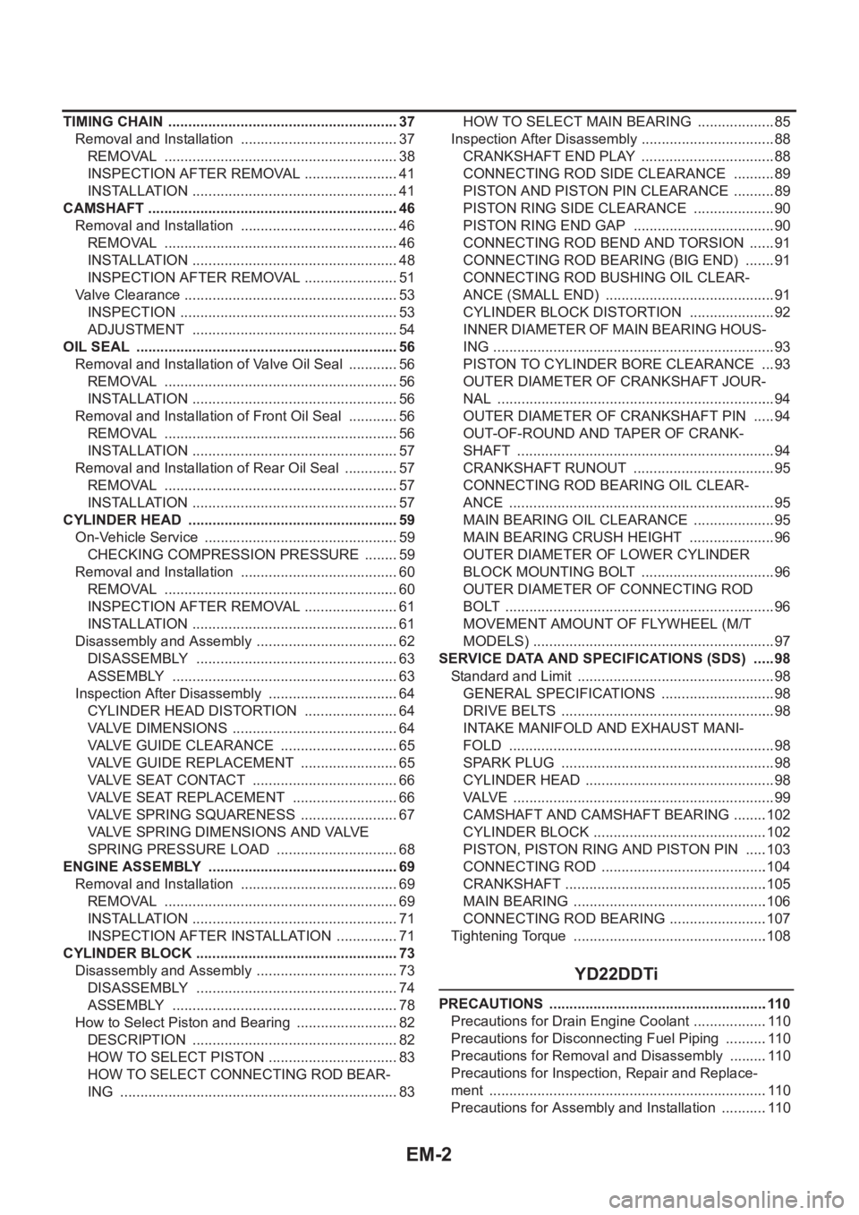
TIMING CHAIN .......................................................... 37
Removal and Installation ........................................ 37
REMOVAL ........................................................... 38
INSPECTION AFTER REMOVAL ........................ 41
INSTALLATION .................................................... 41
CAMSHAFT ............................................................... 46
Removal and Installation ........................................ 46
REMOVAL ........................................................... 46
INSTALLATION .................................................... 48
INSPECTION AFTER REMOVAL ........................ 51
Valve Clearance ...................................................... 53
INSPECTION ....................................................... 53
ADJUSTMENT .................................................... 54
OIL SEAL .................................................................. 56
Removal and Installation of Valve Oil Seal ............. 56
REMOVAL ........................................................... 56
INSTALLATION .................................................... 56
Removal and Installation of Front Oil Seal ............. 56
REMOVAL ........................................................... 56
INSTALLATION .................................................... 57
Removal and Installation of Rear Oil Seal .............. 57
REMOVAL ........................................................... 57
INSTALLATION .................................................... 57
CYLINDER HEAD .................................................. ... 59
On-Vehicle Service ................................................. 59
CHECKING COMPRESSION PRESSURE ......... 59
Removal and Installation ........................................ 60
REMOVAL ........................................................... 60
INSPECTION AFTER REMOVAL ........................ 61
INSTALLATION .................................................... 61
Disassembly and Assembly .................................... 62
DISASSEMBLY ................................................... 63
ASSEMBLY ......................................................... 63
Inspection After Disassembly ................................. 64
CYLINDER HEAD DISTORTION ........................ 64
VALVE DIMENSIONS .......................................... 64
VALVE GUIDE CLEARANCE .............................. 65
VALVE GUIDE REPLACEMENT ......................... 65
VALVE SEAT CONTACT ..................................... 66
VALVE SEAT REPLACEMENT ........................... 66
VALVE SPRING SQUARENESS ......................... 67
VALVE SPRING DIMENSIONS AND VALVE
SPRING PRESSURE LOAD ............................... 68
ENGINE ASSEMBLY ................................................ 69
Removal and Installation ........................................ 69
REMOVAL .......................................................
.... 69
INSTALLATION .................................................... 71
INSPECTION AFTER INSTALLATION ................ 71
CYLINDER BLOCK ................................................... 73
Disassembly and Assembly .................................... 73
DISASSEMBLY ................................................... 74
ASSEMBLY ......................................................... 78
How to Select Piston and Bearing .......................... 82
DESCRIPTION .................................................... 82
HOW TO SELECT PISTON ................................. 83
HOW TO SELECT CONNECTING ROD BEAR-
ING ...................................................................... 83HOW TO SELECT MAIN BEARING .................... 85
Inspection After Disassembly .................................. 88
CRANKSHAFT END PLAY .................................. 88
CONNECTING ROD SIDE CLEARANCE ........... 89
PISTON AND PISTON PIN CLEARANCE ........... 89
PISTON RING SIDE CLEARANCE ..................... 90
PISTON RING END GAP .................................... 90
CONNECTING ROD BEND AND TORSION ....... 91
CONNECTING ROD BEARING (BIG END) ........ 91
CONNECTING ROD BUSHING OIL CLEAR-
ANCE (SMALL END) ........................................... 91
CYLINDER BLOCK DISTORTION ...................... 92
INNER DIAMETER OF MAIN BEARING HOUS-
ING ....................................................................... 93
PISTON TO CYLINDER BORE CLEARANCE .... 93
OUTER DIAMETER OF CRANKSHAFT JOUR-
NAL ...................................................................... 94
OUTER DIAMETER OF CRANKSHAFT PIN ...... 94
OUT-OF-ROUND AND TAPER OF CRANK-
SHAFT ................................................................. 94
CRANKSHAFT RUNOUT .................................... 95
CONNECTING ROD BEARING OIL CLEAR-
ANCE ................................................................... 95
MAIN BEARING OIL CLEARANCE ..................... 95
MAIN BEARING CRUSH HEIGHT ...................... 96
OUTER DIAMETER OF LOWER CYLINDER
BLOCK MOUNTING BOLT .................................. 96
OUTER DIAMETER OF CONNECTING ROD
BOLT .................................................................... 96
MOVEMENT AMOUNT OF FLYWHEEL (M/T
MODELS) ............................................................. 97
SERVICE DATA AND SPECIFICATIONS (SDS) ...... 98
Standard and Limit .................................................. 98
GENERAL SPECIFICATIONS ............................. 98
DRIVE BELTS ...................................................... 98
INTAKE MANIFOLD AND EXHAUST MANI-
FOLD ................................................................... 98
SPARK PLUG ...................................................... 98
CYLINDER HEAD ................................................ 98
VALVE .................................................................. 99
CAMSHAFT AND CAMSHAFT BEARING .........102
CYLINDER BLOCK ............................................102
PISTON, PISTON RING AND PISTON PIN .....
.103
CONNECTING ROD ..........................................104
CRANKSHAFT ...................................................105
MAIN BEARING .................................................106
CONNECTING ROD BEARING .........................107
Tightening Torque .................................................108
YD22DDTi
PRECAUTIONS .......................................................110
Precautions for Drain Engine Coolant ...................110
Precautions for Disconnecting Fuel Piping ...........110
Precautions for Removal and Disassembly ..........110
Precautions for Inspection, Repair and Replace-
ment ......................................................................110
Precautions for Assembly and Installation ............110
Page 53 of 3833

EM-3
C
D
E
F
G
H
I
J
K
L
M
EMA Parts Requiring Angular Tightening ...................... 110
Precautions For Liquid Gasket ............................. . 111
REMOVAL OF LIQUID GASKET ...................... . 111
LIQUID GASKET APPLICATION PROCEDURE . . 111
PREPARATION ........................................................112
Special Service Tools ............................................ 112
Commercial Service Tools ..................................... 115
NOISE, VIBRATION, AND HARSHNESS (NVH)
TROUBLESHOOTING .............................................116
NVH Troubleshooting —Engine Noise .................. 116
Use the Chart Below to Help You Find the Cause
of the Symptom. .................................................... 117
DRIVE BELTS ..........................................................118
Checking Drive Belts ............................................. 118
Tension Adjustment ............................................... 118
AIR CONDITIONER COMPRESSOR BELT ...... 119
ALTERNATOR AND WATER PUMP BELT ........ 119
Removal and Installation ....................................... 119
REMOVAL .......................................................... 119
INSTALLATION .................................................. 119
AIR CLEANER AND AIR DUCT ............................. 120
Removal and Installation ...................................... 120
REMOVAL ......................................................... 120
INSTALLATION ................................................. 120
CHANGING AIR CLEANER FILTER ................. 121
CHARGE AIR COOLER ......................................... 122
Removal and Installation ...................................... 122
REMOVAL ......................................................... 122
INSPECTION AFTER REMOVAL ..................... 122
INSTALLATION ................................................. 122
INTAKE MANIFOLD ............................................... 123
Removal and Installation ...................................... 123
REMOVAL ......................................................... 123
INSPECTION AFTER REMOVAL ..................... 124
INSTALLATION ................................................. 124
INSPECTION AFTER INSTALLATION ............. 125
CATALYST .............................................................. 126
Removal and Installation ...................................... 126
REMOVAL ......................................................... 126
INSTALLATION ................................................. 126
EXHAUST MANIFOLD AND TURBOCHARGER .. 127
Removal and Installation ...................................... 127
REMOVAL ......................................................... 127
INSTALLATION ................................................. 128
INSPECTION AFTER INSTALLATION ............. 128
Disassembly and Assembly ................................. 129
REMOVAL ......................................................... 129
INSPECTION AFTER REMOVAL ..................... 129
Turbocharger ........................................................ 130
ROTOR SHAFT CLEARANCE ......................... 130
ROTOR SHAFT END PLAY .............................. 130
TURBINE WHEEL ............................................. 131
COMPRESSOR WHEEL .................................. 131
WASTEGATE VALVE ACTUATOR ................... 131
TROUBLE DIAGNOSIS OF TURBOCHARGER . 132OIL PAN AND OIL STRAINER ...............................133
Removal and Installation ......................................133
REMOVAL .........................................................133
INSPECTION AFTER REMOVAL .....................135
INSTALLATION .................................................135
INSPECTION AFTER INSTALLATION ..............137
GLOW PLUG ..........................................................138
Removal and Installation ......................................138
REMOVAL .........................................................138
INSTALLATION .................................................138
VACUUM PUMP ......................................................139
Removal and Installation ......................................139
MODELS PRODUCED BEFORE MARCH 2001 .139
MODELS PRODUCED SINCE APRIL 2001 .....140
INSPECTION BEFORE REMOVAL ..................140
REMOVAL .........................................................140
INSTALLATION .................................................141
INSPECTION AFTER INSTALLATION ..............142
Disassembly and Assembly ..................................142
DISASSEMBLY .................................................142
ASSEMBLY .......................................................142
INJECTION TUBE AND FUEL INJECTOR ............144
Removal and Installation ......................................144
REMOVAL .........................................................144
INSTALLATION .................................................145
INSPECTION AFTER INSTALLATION ..............146
FUEL SUPPLY PUMP .............................................147
Removal and Installation ......................................147
REMOVAL .........................................................147
INSPECTION AFTER REMOVAL .....................152
INSTALLATION .................................................152
ROCKER COVER ...................................................156
Removal and Installation ......................................156
REMOVAL .........................................................156
INSTALLATION .................................................157
INSPECTION AFTER INSTALLATION .............
.157
CAMSHAFT ............................................................158
Removal and Installation ......................................158
REMOVAL .........................................................158
INSPECTION AFTER REMOVAL .....................159
INSTALLATION .................................................162
Valve Clearance ...................................................163
INSPECTION ....................................................163
ADJUSTMENTS ................................................164
SECONDARY TIMING CHAIN ................................167
Removal and Installation ......................................167
REMOVAL .........................................................167
INSPECTION AFTER REMOVAL .....................169
INSTALLATION .................................................170
PRIMARY TIMING CHAIN ......................................172
Removal and Installation ......................................172
REMOVAL .........................................................174
INSPECTION AFTER REMOVAL .....................177
INSTALLATION .................................................177
CYLINDER HEAD .................................................. .182
On-Vehicle Service ...............................................182
CHECKING COMPRESSION PRESSURE .......182
Removal and Installation ......................................183
REMOVAL .........................................................183
Page 61 of 3833
![NISSAN X-TRAIL 2001 Service Repair Manual NOISE, VIBRATION, AND HARSHNESS (NVH) TROUBLESHOOTING
EM-11
[QR]
C
D
E
F
G
H
I
J
K
L
MA
EM
Use the Chart Below to Help You Find the Cause of the Symptom.EBS00L7Q
1. Locate the area where noise occurs.](/manual-img/5/57405/w960_57405-60.png "NISSAN X-TRAIL 2001 Service Repair Manual NOISE, VIBRATION, AND HARSHNESS (NVH) TROUBLESHOOTING
EM-11
[QR]
C
D
E
F
G
H
I
J
K
L
MA
EM
Use the Chart Below to Help You Find the Cause of the Symptom.EBS00L7Q
1. Locate the area where noise occurs.")
NOISE, VIBRATION, AND HARSHNESS (NVH) TROUBLESHOOTING
EM-11
[QR]
C
D
E
F
G
H
I
J
K
L
MA
EM
Use the Chart Below to Help You Find the Cause of the Symptom.EBS00L7Q
1. Locate the area where noise occurs.
2. Confirm the type of noise.
3. Specify the operating condition of engine.
4. Check specified noise source.
If necessary, repair or replace these parts.
A: Closely related B: Related C: Sometimes related —: Not relatedLocation
of noiseType of
noiseOperating condition of engine
Source of
noiseCheck itemRefer-
ence page Before
warm-
upAfter
warm-
upWhen
start-
ingWhen
idlingWhen
racingWhile
driving
Top of
engine
Rocker
cover
Cylinder
headTicking or
clickingCA—AB—Tappet
noiseValve clearanceEM-53
Rattle C A — A B CCamshaft
bearing
noiseCamshaft journal clear-
ance
Camshaft runoutEM-51EM-51
Crank-
shaft pul-
ley
Cylinder
block
(Side of
engine)
Oil panSlap or
knock—A—BB—Piston pin
noisePiston and piston pin
clearance
Connecting rod bush-
ing oil clearance (Small
end)EM-89
EM-91
Slap or
rapA ——BBAPiston
slap noisePiston to cylinder bore
clearance
Piston ring side clear-
ance
Piston ring end gap
Connecting rod bend
and torsionEM-94EM-90
EM-90
EM-91
Knock A B C B B BConnect-
ing rod
bearing
noiseConnecting rod bush-
ing oil clearance (Small
end)
Connecting rod bear-
ing clearance (Big end)EM-91EM-91
Knock A B — A B CMain
bearing
noiseMain bearing oil clear-
ance
Crankshaft runoutEM-95EM-95
Front of
engine
Timing
chain
coverTapping or
tickingA A —BBBTiming
chain and
chain ten-
sioner
noiseTiming chain cracks
and wear
Timing chain tensioner
operationEM-37
Front of
engineSqueak-
ing or fizz-
ingAB—B—CDrive belts
(Sticking
or slip-
ping)Drive belts deflection
EM-12
CreakingA B ABABDrive belts
(Slipping)Idler pulley bearing
operation
Squall
CreakA B —BABWater
pump
noiseWater pump operationCO-18,
"WATER
PUMP"
Page 88 of 3833
![NISSAN X-TRAIL 2001 Service Repair Manual EM-38
[QR]
TIMING CHAIN
REMOVAL
1. Remove the parts listed below.
●Engine hood
●Engine undercover
●PCV hose
●Ignition coil; Refer to EM-29, "IGNITION COIL" .
●Rocker cover; Refer to](/manual-img/5/57405/w960_57405-87.png "NISSAN X-TRAIL 2001 Service Repair Manual EM-38
[QR]
TIMING CHAIN
REMOVAL
1. Remove the parts listed below.
●Engine hood
●Engine undercover
●PCV hose
●Ignition coil; Refer to EM-29, \"IGNITION COIL\" .
●Rocker cover; Refer to")
EM-38
[QR]
TIMING CHAIN
REMOVAL
1. Remove the parts listed below.
●Engine hood
●Engine undercover
●PCV hose
●Ignition coil; Refer to EM-29, "IGNITION COIL" .
●Rocker cover; Refer to EM-35, "ROCKER COVER" .
●Engine coolant reservoir tank
●Drive belt; Refer to EM-12, "REMOVAL" .
●Alternator
●Drive belt auto-tensioner; Refer to EM-13, "REMOVAL" .
●Exhaust front tube; Refer to EX-2, "Removal and Installation" .
2. Remove A/C compressor from engine. Temporarily secure A/C compressor to vehicle side with a rope to
avoid putting a load on them.
3. Remove bracket mounting bolts for fixing A/C piping on right strut housing and exhaust manifold cover.
Doing so simplifies moving.
4. Move power steering pump with piping connected, and secure it to vehicle side temporarily.
5. Pull power steering reservoir tank out of brackets to move power steering piping.
CAUTION:
To avoid power steering fluid leakage, temporarily fix reservoir tank vertically.
6. Suspend engine with a hoist, and support the engine posture.
For installation of engine slingers, refer to EM-69, "
ENGINE ASSEMBLY" .
7. Remove RH engine mount insulator.
8. Remove center member and rear engine mounting bracket.
9. Drain engine oil.
10. Remove oil pan upper and lower, and oil strainer. Refer to EM-26, "
OIL PAN AND OIL STRAINER" .
11. Remove intake valve timing control cover.
a. Loosen bolts in reverse order shown in the figure.
b. Remove the cover using Tool (Seal cutter).
CAUTION:
Be careful not to damage mounting surface.
12. Pull chain guide between camshaft sprockets out through front
cover.
13. Set No. 1 cylinder at TDC on its compression stroke with the fol-
lowing procedure.
a. Rotate crankshaft pulley clockwise and align mating marks to
timid indicator on front cover.
KBIA0085E
KBIA0190E
Page 94 of 3833
![NISSAN X-TRAIL 2001 Service Repair Manual EM-44
[QR]
TIMING CHAIN
d. Tighten mounting bolts in the numerical order shown in the fig-
ure.
e. After all bolts are tightened, retighten them to specified torque.
CAUTION:
Be sure to w](/manual-img/5/57405/w960_57405-93.png "NISSAN X-TRAIL 2001 Service Repair Manual EM-44
[QR]
TIMING CHAIN
d. Tighten mounting bolts in the numerical order shown in the fig-
ure.
e. After all bolts are tightened, retighten them to specified torque.
CAUTION:
Be sure to w")
EM-44
[QR]
TIMING CHAIN
d. Tighten mounting bolts in the numerical order shown in the fig-
ure.
e. After all bolts are tightened, retighten them to specified torque.
CAUTION:
Be sure to wipe off any excessive liquid gasket leaking to
surface for fitting oil pan.
8. Install chain guide between camshaft sprockets.
9. Install intake valve timing control cover with the following procedure.
a. Install intake valve timing control solenoid valves to intake valve timing control cover.
b. Install oil rings to the intake camshaft sprocket insertion points on intake valve timing control backside
cover.
c. Install O-ring to front cover.
d. Apply liquid gasket to the positions in the figure.
Use Genuine Liquid gasket or equivalent.
e. Tighten mounting bolts in the numerical order shown in the fig-
ure.
10. Insert crankshaft pulley by aligning with crankshaft key.
●Tap its center with a plastic hammer to insert.
●Do not tap belt hook.
11. Tighten crankshaft pulley mounting bolt.
KBIA0083E
SBIA0260E
KBIA0085E
Page 106 of 3833
![NISSAN X-TRAIL 2001 Service Repair Manual EM-56
[QR]
OIL SEAL
OIL SEAL
PFP:12279
Removal and Installation of Valve Oil SealEBS00KNM
REMOVAL
1. Remove camshaft. Refer to EM-46, "CAMSHAFT" .
2. Remove valve lifter. Refer to EM-46, "](/manual-img/5/57405/w960_57405-105.png "NISSAN X-TRAIL 2001 Service Repair Manual EM-56
[QR]
OIL SEAL
OIL SEAL
PFP:12279
Removal and Installation of Valve Oil SealEBS00KNM
REMOVAL
1. Remove camshaft. Refer to EM-46, \"CAMSHAFT\" .
2. Remove valve lifter. Refer to EM-46, \"")
EM-56
[QR]
OIL SEAL
OIL SEAL
PFP:12279
Removal and Installation of Valve Oil SealEBS00KNM
REMOVAL
1. Remove camshaft. Refer to EM-46, "CAMSHAFT" .
2. Remove valve lifter. Refer to EM-46, "
CAMSHAFT" .
3. Rotate crankshaft, and set piston whose oil seal is to be
removed to top dead center. This prevents valve from dropping
inside cylinder.
CAUTION:
When rotating crankshaft, be careful to avoid scarring the
front cover with the timing chain.
4. Remove valve collet, valve spring retainer and valve spring with
SST. Refer to EM-59, "
CYLINDER HEAD" .
5. Remove valve oil seal with SST.
INSTALLATION
1. Apply new engine oil to valve oil seal joint surface and seal lip.
2. Press in valve oil seal to the position shown in the figure with
SST.
3. Install followings in the reverse order of removal.
Removal and Installation of Front Oil SealEBS00KNN
REMOVAL
1. Remove the parts listed below.
●Under cover (with splash cover).
●Drive belts. Refer to EM-12, "DRIVE BELTS" .
●Crank pulley. Refer to EM-37, "TIMING CHAIN" .
2. Remove front oil seal.
CAUTION:
Be careful not to damage front cover and crankshaft.
PBIC0277E
SEM093F
SBIA0270E
Page 167 of 3833
![NISSAN X-TRAIL 2001 Service Repair Manual NOISE, VIBRATION, AND HARSHNESS (NVH) TROUBLESHOOTING
EM-117
[YD22DDTi]
C
D
E
F
G
H
I
J
K
L
MA
EM
Use the Chart Below to Help You Find the Cause of the Symptom.EBS00LR9
1. Locate the area where noise](/manual-img/5/57405/w960_57405-166.png "NISSAN X-TRAIL 2001 Service Repair Manual NOISE, VIBRATION, AND HARSHNESS (NVH) TROUBLESHOOTING
EM-117
[YD22DDTi]
C
D
E
F
G
H
I
J
K
L
MA
EM
Use the Chart Below to Help You Find the Cause of the Symptom.EBS00LR9
1. Locate the area where noise")
NOISE, VIBRATION, AND HARSHNESS (NVH) TROUBLESHOOTING
EM-117
[YD22DDTi]
C
D
E
F
G
H
I
J
K
L
MA
EM
Use the Chart Below to Help You Find the Cause of the Symptom.EBS00LR9
1. Locate the area where noise occurs.
2. Confirm the type of noise.
3. Specify the operating condition of engine.
4. Check specified noise source.
If necessary, repair or replace these parts.
A: Closely related B: Related C: Sometimes related —: Not relatedLocation
of noiseType of
noiseOperating condition of engine
Source of
noiseCheck itemRefer-
ence page Before
warm-
upAfter
warm-
upWhen
start-
ingWhen
idlingWhen
racingWhile
driving
Top of
engine
Rocker
cover
Cylinder
headTicking or
clickingCA—AB—Tappet
noiseValve clearanceEM-163
Rattle C A — A B CCamshaft
bearing
noiseCamshaft oil clearance
Camshaft runoutEM-160EM-159
Crank-
shaft pul-
ley
Cylinder
block
(Side of
engine)
Oil panSlap or
knock—A—BB—Piston pin
noisePiston to piston pin
clearance
Connecting rod bush-
ing oil clearance (Small
end)EM-210
EM-212
Slap or
rapA ——BBAPiston
slap noisePiston to cylinder bore
clearance
Piston ring side clear-
ance
Piston ring end gap
Connecting rod bend
and torsionEM-214EM-211
EM-211
EM-212
Knock A B C B B BConnect-
ing rod
bearing
noiseConnecting rod bush-
ing oil clearance (Small
end)
Connecting rod bear-
ing oil clearance (Big
end)EM-212EM-216
Knock A B — A B CMain
bearing
noiseMain bearing oil clear-
ance
Crankshaft runoutEM-216EM-216
Front of
engine
Timing
chain
coverTapping or
tickingA A —BBBTiming
chain and
chain ten-
sioner
noiseTiming chain cracks
and wear
Timing chain tensioner
operationEM-167
EM-172
Front of
engineSqueak-
ing or fizz-
ingAB—B—CDrive belts
(Sticking
or slip-
ping)Drive belts deflection
EM-118
CreakingA B ABABDrive belts
(Slipping)Idler pulley bearing
operation
Squall
CreakA B —BABWater
pump
noiseWater pump operationCO-39,
"WATER
PUMP"
Page 270 of 3833
![NISSAN X-TRAIL 2001 Service Repair Manual EM-220
[YD22DDTi]
SERVICE DATA AND SPECIFICATIONS (SDS)
SERVICE DATA AND SPECIFICATIONS (SDS)
PFP:00030
Standard and LimitEBS00ODZ
GENERAL SPECIFICATIONS
INTAKE MANIFOLD AND EXHAUST MANIFOLD
Unit: mm](/manual-img/5/57405/w960_57405-269.png "NISSAN X-TRAIL 2001 Service Repair Manual EM-220
[YD22DDTi]
SERVICE DATA AND SPECIFICATIONS (SDS)
SERVICE DATA AND SPECIFICATIONS (SDS)
PFP:00030
Standard and LimitEBS00ODZ
GENERAL SPECIFICATIONS
INTAKE MANIFOLD AND EXHAUST MANIFOLD
Unit: mm")
EM-220
[YD22DDTi]
SERVICE DATA AND SPECIFICATIONS (SDS)
SERVICE DATA AND SPECIFICATIONS (SDS)
PFP:00030
Standard and LimitEBS00ODZ
GENERAL SPECIFICATIONS
INTAKE MANIFOLD AND EXHAUST MANIFOLD
Unit: mm (in)
DRIVE BELTS
Belt Deflection:
Unit: mm (in)
*: When engine is cold.Cylinder arrangementIn-line 4
Displacement
Unit: cm
3 (cu in)2,184 (133.27)
Bore and stroke Unit: mm (in) 86 x 94 (3.39 x 3.70)
Valve arrangementDOHC
Firing order1-3-4-2
Number of piston ringsCompression 2
Oil 1
Number of main bearings5
Compression ratio16.0
Compression pressure
Unit: kPa (bar, kg/cm
2 , psi)/200 rpmStandard 2,893 (28.9, 29.5, 419)
Minimum 2,452 (24.5, 25.0, 356)
Differential limit between cylinders 490 (4.9, 5.0, 71)
Valve timing
Unit: degree
abc de f
224 212 2 30 -2 46
EM120
Item Limit
Surface distortionIntake manifold 0.1 (0.004)
Exhaust manifold 0.3 (0.012)
Applied beltBelt deflection with 98 N (10 kg, 22 lb) force applied*
New Adjusted Limit for re-adjusting
Air conditioner compressor belt4 - 5
(0.16 - 0.20)6 - 7
(0.24 - 0.28)8.5 (0.335)
Alternator & water pump belt9.0 - 10.5
(0.354 - 0.413)11.0 - 12.5
(0.433 - 0.492)16.5 (0.650)