2001 NISSAN X-TRAIL tire size
[x] Cancel search: tire sizePage 240 of 3833
![NISSAN X-TRAIL 2001 Service Repair Manual EM-190
[YD22DDTi]
CYLINDER HEAD
3. Remove cylinder head valve guide hole.
4. Heat cylinder head to 110 to 130°C (230 to 266°F) in oil bath.
5. Using valve guide drift, press fit valve guides NISSAN X-TRAIL 2001 Service Repair Manual EM-190
[YD22DDTi]
CYLINDER HEAD
3. Remove cylinder head valve guide hole.
4. Heat cylinder head to 110 to 130°C (230 to 266°F) in oil bath.
5. Using valve guide drift, press fit valve guides](/manual-img/5/57405/w960_57405-239.png)
EM-190
[YD22DDTi]
CYLINDER HEAD
3. Remove cylinder head valve guide hole.
4. Heat cylinder head to 110 to 130°C (230 to 266°F) in oil bath.
5. Using valve guide drift, press fit valve guides from camshaft
side, referring to the dimension shown in the figure.
CAUTION:
Cylinder head contains heat, when working, wear protective
equipment to avoid getting burned.
6. Using valve guide reamer, perform reaming to the press-fitted
valve guides.
Valve Seat Contact
●Before starting this check, confirm that the dimension of valve
guide and valves are as specified.
●Apply red lead primer on contacting surfaces of valves seat and
of valve face to examine the conditions of contacting surfaces.
●Check that the paint on contacting surfaces is continuous along
the entire circumference.
●If there are abnormal indications, grind the valve and check the
contact again. If abnormal indications still persist, replace valve
seat.
Valve Seat Replacement
●When removing valve seat, replace it with oversized [0.5 mm (0.020 in)] valve seat.
1. Cut valve seat to make it thin, and pull it out.Valve guide hole diameter (for service parts):
10.175 - 10.196 mm (0.4006 - 0.4014 in)
SEM932C
Projection “L” : 10.4 - 10.6 mm (0.409 - 0.417 in)
JEM156G
Reaming specifications:
Intake and Exhaust
6.000 - 6.018 mm (0.2362 - 0.2369 in)
FEM072
SBIA0322E
Page 312 of 3833
![NISSAN X-TRAIL 2001 Service Repair Manual CO-6
[QR]
OVERHEATING CAUSE ANALYSIS
Except cool-
ing system
parts mal-
function— Overload on engineAbusive drivingHigh engine rpm under no
load
Driving in low gear for
extended time
Driving at e NISSAN X-TRAIL 2001 Service Repair Manual CO-6
[QR]
OVERHEATING CAUSE ANALYSIS
Except cool-
ing system
parts mal-
function— Overload on engineAbusive drivingHigh engine rpm under no
load
Driving in low gear for
extended time
Driving at e](/manual-img/5/57405/w960_57405-311.png)
CO-6
[QR]
OVERHEATING CAUSE ANALYSIS
Except cool-
ing system
parts mal-
function— Overload on engineAbusive drivingHigh engine rpm under no
load
Driving in low gear for
extended time
Driving at extremely high
speed
Powertrain system mal-
function
— Installed improper size
wheels and tires
Dragging brakes
Improper ignition timing
Blocked or restricted air
flowBlocked bumper —
— Blocked radiator grilleInstalled car brassiere
Mud contamination or
paper clogging
Blocked radiator —
Blocked condenser
Blocked air flow
Installed large fog lamp Symptom Check items
Page 332 of 3833
![NISSAN X-TRAIL 2001 Service Repair Manual CO-26
[YD22DDTi]
OVERHEATING CAUSE ANALYSIS
Except cool-
ing system
parts mal-
function— Overload on engineAbusive drivingHigh engine rpm under no
load
Driving in low gear for
extended time
Drivi NISSAN X-TRAIL 2001 Service Repair Manual CO-26
[YD22DDTi]
OVERHEATING CAUSE ANALYSIS
Except cool-
ing system
parts mal-
function— Overload on engineAbusive drivingHigh engine rpm under no
load
Driving in low gear for
extended time
Drivi](/manual-img/5/57405/w960_57405-331.png)
CO-26
[YD22DDTi]
OVERHEATING CAUSE ANALYSIS
Except cool-
ing system
parts mal-
function— Overload on engineAbusive drivingHigh engine rpm under no
load
Driving in low gear for
extended time
Driving at extremely high
speed
Powertrain system mal-
function
— Installed improper size
wheels and tires
Dragging brakes
Improper ignition timing
Blocked or restricted air
flowBlocked bumper —
— Blocked radiator grilleInstalled car brassiere
Mud contamination or
paper clogging
Blocked radiator —
Blocked condenser
Blocked air flow
Installed large fog lamp Symptom Check items
Page 2652 of 3833
TF-42
TROUBLE DIAGNOSIS
NOTE:
1. Light tight-corner braking symptom may occur depending on driving conditions in AUTO mode. This is not
malfunction.
2. Heavy tight-corner braking symptom occurs when vehicle is driven in the following conditions: LOCK
mode, steering wheel is turned fully to either sides, and accelerator pedal was depressed.
3. When the difference of revolution speed between the front and the rear wheels is large, the 4WD mode
does not change to other mode.this is not a malfunction.
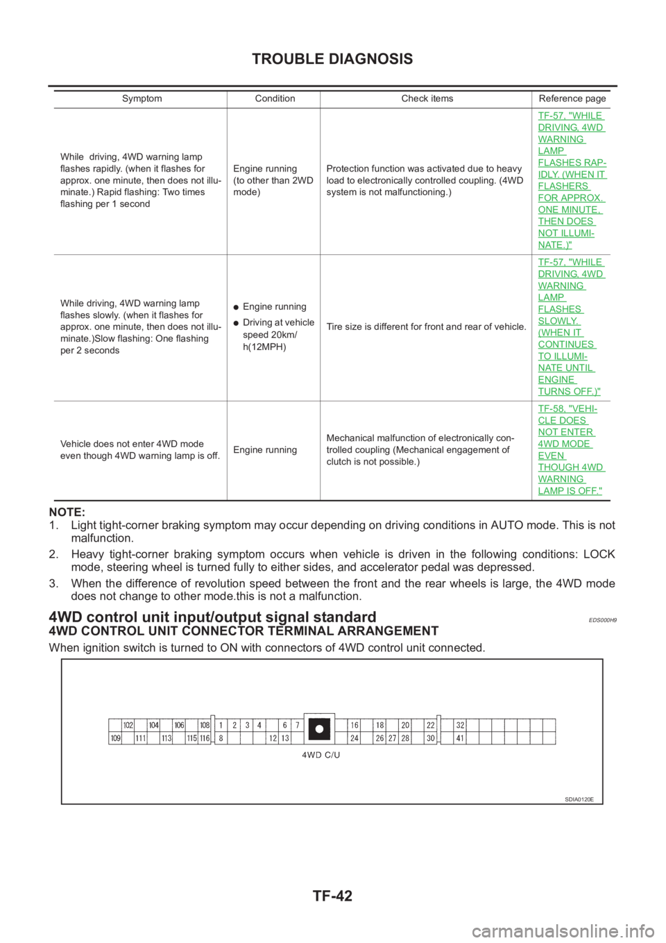
4WD control unit input/output signal standardEDS000H9
4WD CONTROL UNIT CONNECTOR TERMINAL ARRANGEMENT
When ignition switch is turned to ON with connectors of 4WD control unit connected.
While driving, 4WD warning lamp
flashes rapidly. (when it flashes for
approx. one minute, then does not illu-
minate.) Rapid flashing: Two times
flashing per 1 secondEngine running
(to other than 2WD
mode)Protection function was activated due to heavy
load to electronically controlled coupling. (4WD
system is not malfunctioning.)TF-57, "
WHILE
DRIVING, 4WD
WARNING
LAMP
FLASHES RAP-
IDLY. (WHEN IT
FLASHERS
FOR APPROX.
ONE MINUTE,
THEN DOES
NOT ILLUMI-
NATE.)"
While driving, 4WD warning lamp
flashes slowly. (when it flashes for
approx. one minute, then does not illu-
minate.)Slow flashing: One flashing
per 2 seconds●Engine running
●Driving at vehicle
speed 20km/
h(12MPH)Tire size is different for front and rear of vehicle.TF-57, "
WHILE
DRIVING, 4WD
WARNING
LAMP
FLASHES
SLOWLY.
(WHEN IT
CONTINUES
TO ILLUMI-
NATE UNTIL
ENGINE
TURNS OFF.)"
Vehicle does not enter 4WD mode
even though 4WD warning lamp is off.Engine runningMechanical malfunction of electronically con-
trolled coupling (Mechanical engagement of
clutch is not possible.)TF-58, "
VEHI-
CLE DOES
NOT ENTER
4WD MODE
EVEN
THOUGH 4WD
WARNING
LAMP IS OFF."
Symptom Condition Check items Reference page
SDIA0120E
Page 2654 of 3833
TF-44
TROUBLE DIAGNOSIS
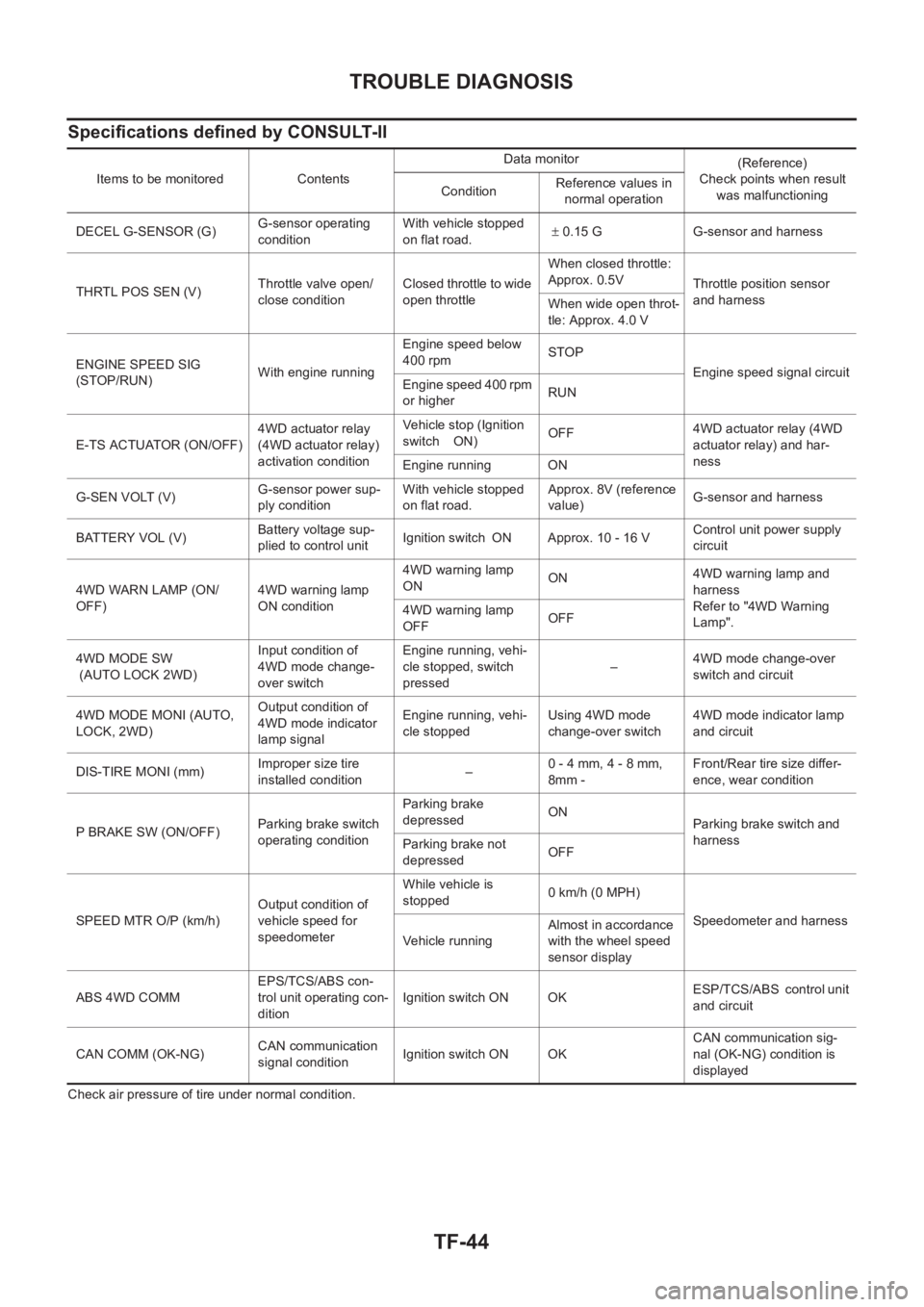
Specifications defined by CONSULT-II
Check air pressure of tire under normal condition.Items to be monitored ContentsData monitor
(Reference)
Check points when result
was malfunctioning ConditionReference values in
normal operation
DECEL G-SENSOR (G)G-sensor operating
conditionWith vehicle stopped
on flat road.± 0.15 G G-sensor and harness
THRTL POS SEN (V)Throttle valve open/
close conditionClosed throttle to wide
open throttleWhen closed throttle:
Approx. 0.5V
Throttle position sensor
and harness
When wide open throt-
tle: Approx. 4.0 V
ENGINE SPEED SIG
(STOP/RUN)With engine runningEngine speed below
400 rpmSTOP
Engine speed signal circuit
Engine speed 400 rpm
or higherRUN
E-TS ACTUATOR (ON/OFF)4WD actuator relay
(4WD actuator relay)
activation conditionVehicle stop (Ignition
switch ON)OFF4WD actuator relay (4WD
actuator relay) and har-
ness
Engine running ON
G-SEN VOLT (V)G-sensor power sup-
ply conditionWith vehicle stopped
on flat road.Approx. 8V (reference
value)G-sensor and harness
BATTERY VOL (V)Battery voltage sup-
plied to control unitIgnition switch ON Approx. 10 - 16 VControl unit power supply
circuit
4WD WARN LAMP (ON/
OFF)4WD warning lamp
ON condition4WD warning lamp
ONON4WD warning lamp and
harness
Refer to "4WD Warning
Lamp". 4WD warning lamp
OFFOFF
4WD MODE SW
(AUTO LOCK 2WD)Input condition of
4WD mode change-
over switchEngine running, vehi-
cle stopped, switch
pressed–4WD mode change-over
switch and circuit
4WD MODE MONI (AUTO,
LOCK, 2WD)Output condition of
4WD mode indicator
lamp signalEngine running, vehi-
cle stoppedUsing 4WD mode
change-over switch4WD mode indicator lamp
and circuit
DIS-TIRE MONI (mm)Improper size tire
installed condition
–0 - 4 mm, 4 - 8 mm,
8mm -Front/Rear tire size differ-
ence, wear condition
P BRAKE SW (ON/OFF)Parking brake switch
operating conditionParking brake
depressedON
Parking brake switch and
harness
Parking brake not
depressedOFF
SPEED MTR O/P (km/h)Output condition of
vehicle speed for
speedometerWhile vehicle is
stopped 0 km/h (0 MPH)
Speedometer and harness
Ve h i c le r u n n in gAlmost in accordance
with the wheel speed
sensor display
ABS 4WD COMMEPS/TCS/ABS con-
trol unit operating con-
ditionIgnition switch ON OKESP/TCS/ABS control unit
and circuit
CAN COMM (OK-NG)CAN communication
signal conditionIgnition switch ON OKCAN communication sig-
nal (OK-NG) condition is
displayed
Page 2657 of 3833
TROUBLE DIAGNOSIS
TF-47
C
E
F
G
H
I
J
K
L
MA
B
TF
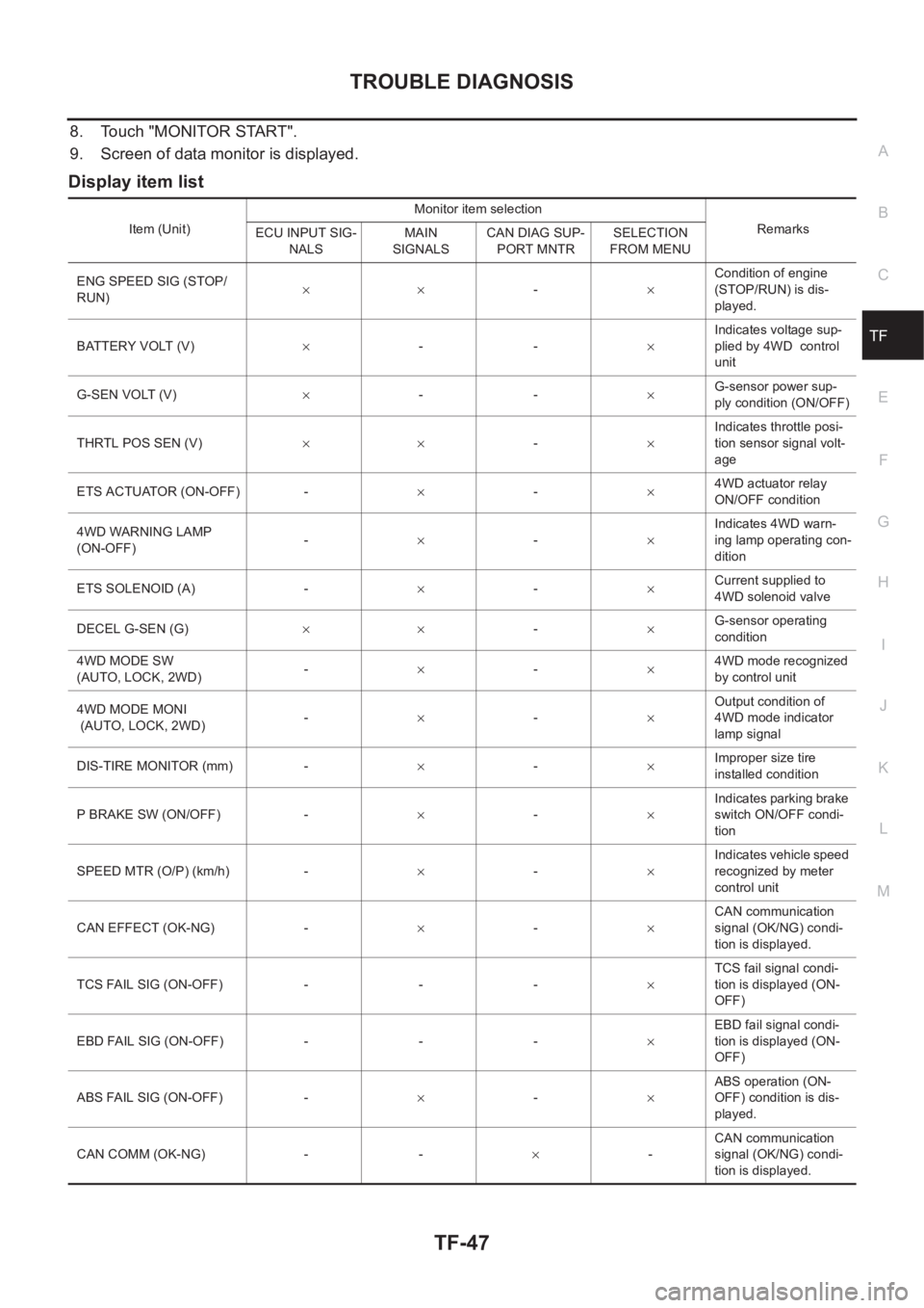
8. Touch "MONITOR START".
9. Screen of data monitor is displayed.
Display item list
Item (Unit)Monitor item selection
Remarks
ECU INPUT SIG-
NALSMAIN
SIGNALSCAN DIAG SUP-
PORT MNTRSELECTION
FROM MENU
ENG SPEED SIG (STOP/
RUN)××-×Condition of engine
(STOP/RUN) is dis-
played.
BATTERY VOLT (V)×--×Indicates voltage sup-
plied by 4WD control
unit
G-SEN VOLT (V)×--×G-sensor power sup-
ply condition (ON/OFF)
THRTL POS SEN (V)××-×Indicates throttle posi-
tion sensor signal volt-
age
ETS ACTUATOR (ON-OFF) -×-×4WD actuator relay
ON/OFF condition
4WD WARNING LAMP
(ON-OFF)-×-×Indicates 4WD warn-
ing lamp operating con-
dition
ETS SOLENOID (A) -×-×Current supplied to
4WD solenoid valve
DECEL G-SEN (G)××-×G-sensor operating
condition
4WD MODE SW
(AUTO, LOCK, 2WD)-×-×4WD mode recognized
by control unit
4WD MODE MONI
(AUTO, LOCK, 2WD)-×-×Output condition of
4WD mode indicator
lamp signal
DIS-TIRE MONITOR (mm) -×-×Improper size tire
installed condition
P BRAKE SW (ON/OFF) -×-×Indicates parking brake
switch ON/OFF condi-
tion
SPEED MTR (O/P) (km/h) -×-×Indicates vehicle speed
recognized by meter
control unit
CAN EFFECT (OK-NG) -×-×CAN communication
signal (OK/NG) condi-
tion is displayed.
TCS FAIL SIG (ON-OFF) - - -×TCS fail signal condi-
tion is displayed (ON-
OFF)
EBD FAIL SIG (ON-OFF) - - -×EBD fail signal condi-
tion is displayed (ON-
OFF)
ABS FAIL SIG (ON-OFF) -×-×ABS operation (ON-
OFF) condition is dis-
played.
CAN COMM (OK-NG) - -×-CAN communication
signal (OK/NG) condi-
tion is displayed.
Page 2668 of 3833
TF-58
TROUBLE DIAGNOSIS
●Perform inspection with the data monitor function of the CONSULT- I I .
●Check if the value of IMPROPER SIZE TIRE MONITOR is 8 mm (0.31 in) or more.
●Stop the engine. Restart the engine and drive the vehicle at 20 km/h (12 MPH) or faster for approxi-
mately 200 seconds. Confirm the 4WD warning lamp flashes slowly.
(Check if the value of IMPROPER SIZE TIRE MONITOR is 8 mm (0.31 in) or more.)
When the tire size is normal, the value of IMPROPER SIZE TIRE MONITOR will change from 8 mm
(0.31 in) or more to 0 to 4 mm (0 to 0.16 in) (normal condition) after the vehicle is driven 20 km/h (12
MPH) or faster for approximately 5 seconds.
2. Tire inspection
●Inspection of tire pressure.
●Wear condition.
●Check size of the front and rear tires. (No excessive difference should be observed.)
VEHICLE DOES NOT ENTER 4WD MODE EVEN THOUGH 4WD WARNING LAMP IS OFF.
1. Check using the data monitor function of the CONSULT-II.
Perform inspection by the data monitor function of the CONSULT-II.
–Check if the vehicle operation changes to 2WD, AUTO, and LOCK modes.
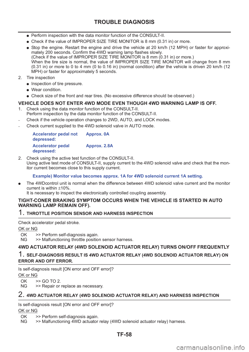
–Check current supplied to the 4WD solenoid valve in AUTO mode.
2. Check using the active test function of the CONSULT-II.
Using active test mode of CONSULT-II, supply current to the 4WD solenoid valve and check that the mon-
itor current becomes close to this supply current.
●The 4WDcontrol unit is normal when the difference between 4WD solenoid valve current and the monitor
current is within ±10%.
It is necessary to inspect the electronically controlled coupling assembly.
TIGHT-CONER BRAKING SYMPTOM OCCURS WHEN THE VEHICLE IS STARTED IN AUTO
WARNING LAMP REMAIN OFF).
1. THROTTLE POSITION SENSOR AND HARNESS INSPECTION
Check accelerator pedal stroke.
OK or NG
OK >> Perform self-diagnosis again.
NG >> Malfunctioning throttle position sensor harness.
4WD ACTUATOR RELAY (4WD SOLENOID ACTUATOR RELAY) TURNS ON/OFF FREQUENTLY
1. SELF-DIAGNOSIS RESULT IS 4WD ACTUATOR RELAY (4WD SOLENOID ACTUATOR RELAY) ON
ERROR AND OFF ERROR.
Is self-diagnosis result [ON error and OFF error]?
OK or NG
OK >> GO TO 2.
NG >> Repair or replace as necessary.
2. 4WD ACTUATOR RELAY (4WD SOLENOID ACTUATOR RELAY) AND HARNESS INSPECTION
Is self-diagnosis result [ON error and OFF error]?
OK or NG
OK >> Perform self-diagnosis again.
NG >> Malfunctioning 4WD actuator relay (4WD solenoid actuator relay) harness. Accelerator pedal not
depressed:Approx. 0A
Accelerator pedal
depressed:Approx. 2.8A
Example) Monitor value becomes approx. 1A for 4WD solenoid current 1A setting.
Page 2736 of 3833
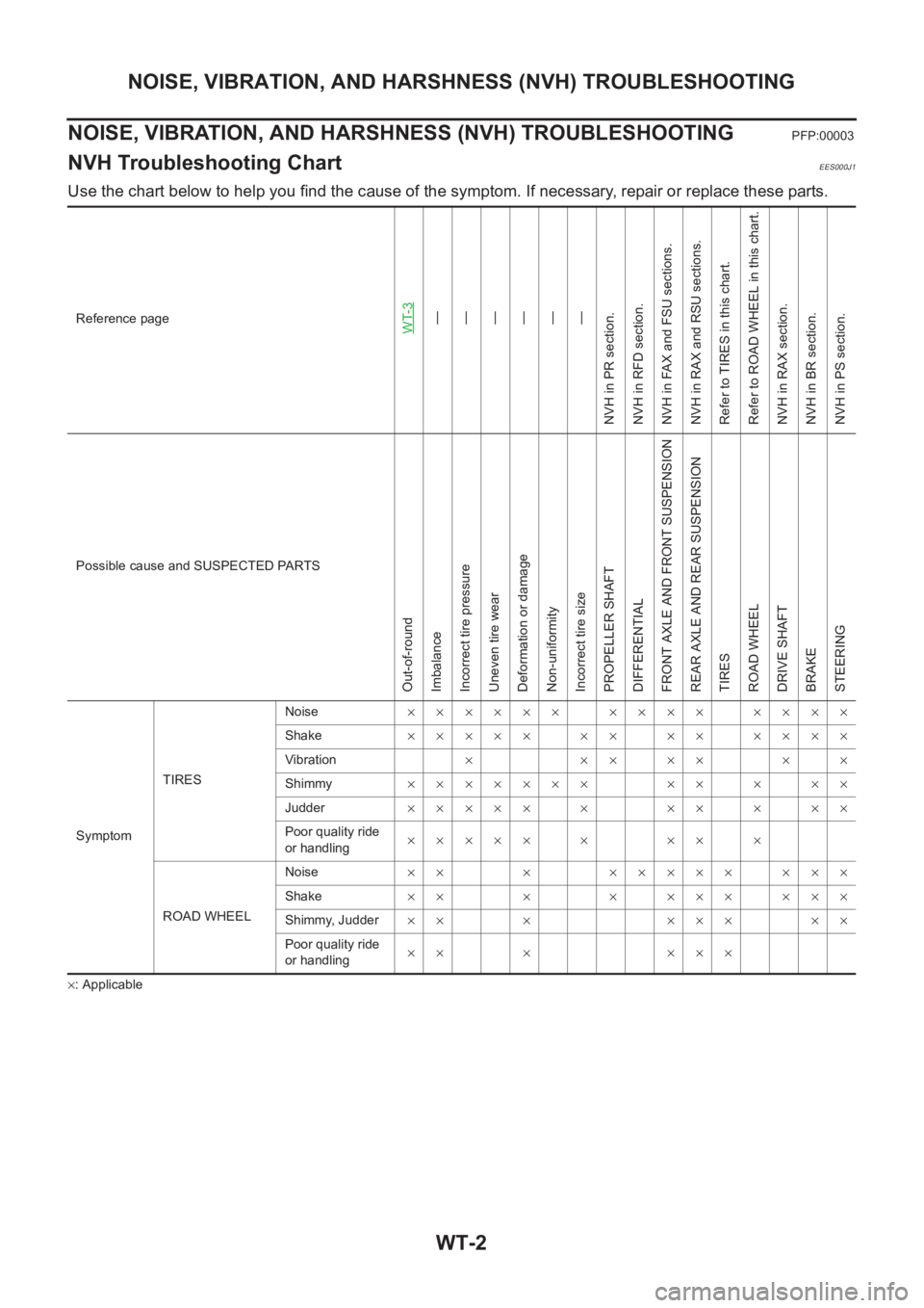
WT-2
NOISE, VIBRATION, AND HARSHNESS (NVH) TROUBLESHOOTING
NOISE, VIBRATION, AND HARSHNESS (NVH) TROUBLESHOOTING
PFP:00003
NVH Troubleshooting ChartEES000J1
Use the chart below to help you find the cause of the symptom. If necessary, repair or replace these parts.
×: ApplicableReference page
WT-3—
—
—
—
—
—
NVH in PR section.
NVH in RFD section.
NVH in FAX and FSU sections.
NVH in RAX and RSU sections.
Refer to TIRES in this chart.
Refer to ROAD WHEEL in this chart.
NVH in RAX section.
NVH in BR section.
NVH in PS section.
Possible cause and SUSPECTED PARTS
Out-of-round
Imbalance
Incorrect tire pressure
Uneven tire wear
Deformation or damage
Non-uniformity
Incorrect tire size
PROPELLER SHAFT
DIFFERENTIAL
FRONT AXLE AND FRONT SUSPENSION
REAR AXLE AND REAR SUSPENSION
TIRES
ROAD WHEEL
DRIVE SHAFT
BRAKE
STEERING
SymptomTIRESNoise×××××× ×××× ××××
Shake××××× ×× ×× ××××
Vibration×××××××
Shimmy××××××× ×× × ××
Judder××××× × ×× × ××
Poor quality ride
or handling××××× × ×× ×
ROAD WHEELNoise×× × ××××× ×××
Shake×× × × ××× ×××
Shimmy, Judder×× × ××× ××
Poor quality ride
or handling×× × ×××