2001 NISSAN X-TRAIL fuse chart
[x] Cancel search: fuse chartPage 19 of 3833
HOW TO USE THIS MANUAL
GI-17
C
D
E
F
G
H
I
J
K
L
MB
GI
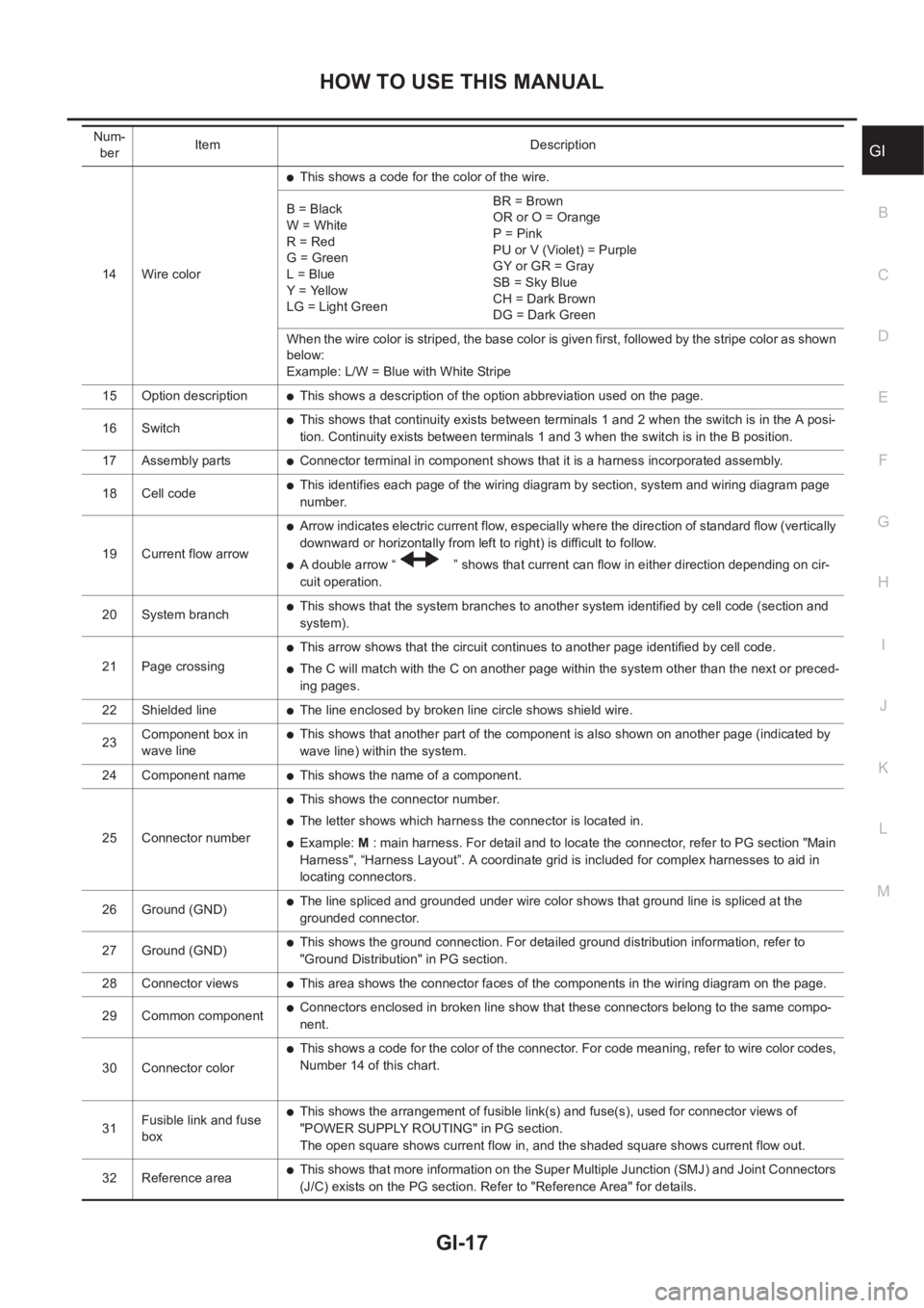
14 Wire color
●This shows a code for the color of the wire.
B = Black
W = White
R = Red
G = Green
L = Blue
Y = Yellow
LG = Light GreenBR = Brown
OR or O = Orange
P = Pink
PU or V (Violet) = Purple
GY or GR = Gray
SB = Sky Blue
CH = Dark Brown
DG = Dark Green
When the wire color is striped, the base color is given first, followed by the stripe color as shown
below:
Example: L/W = Blue with White Stripe
15 Option description
●This shows a description of the option abbreviation used on the page.
16 Switch
●This shows that continuity exists between terminals 1 and 2 when the switch is in the A posi-
tion. Continuity exists between terminals 1 and 3 when the switch is in the B position.
17 Assembly parts
●Connector terminal in component shows that it is a harness incorporated assembly.
18 Cell code
●This identifies each page of the wiring diagram by section, system and wiring diagram page
number.
19 Current flow arrow
●Arrow indicates electric current flow, especially where the direction of standard flow (vertically
downward or horizontally from left to right) is difficult to follow.
●A double arrow “ ” shows that current can flow in either direction depending on cir-
cuit operation.
20 System branch
●This shows that the system branches to another system identified by cell code (section and
system).
21 Page crossing
●This arrow shows that the circuit continues to another page identified by cell code.
●The C will match with the C on another page within the system other than the next or preced-
ing pages.
22 Shielded line
●The line enclosed by broken line circle shows shield wire.
23Component box in
wave line
●This shows that another part of the component is also shown on another page (indicated by
wave line) within the system.
24 Component name
●This shows the name of a component.
25 Connector number
●This shows the connector number.
●The letter shows which harness the connector is located in.
●Example: M : main harness. For detail and to locate the connector, refer to PG section "Main
Harness", “Harness Layout”. A coordinate grid is included for complex harnesses to aid in
locating connectors.
26 Ground (GND)
●The line spliced and grounded under wire color shows that ground line is spliced at the
grounded connector.
27 Ground (GND)
●This shows the ground connection. For detailed ground distribution information, refer to
"Ground Distribution" in PG section.
28 Connector views
●This area shows the connector faces of the components in the wiring diagram on the page.
29 Common component
●Connectors enclosed in broken line show that these connectors belong to the same compo-
nent.
30 Connector color
●This shows a code for the color of the connector. For code meaning, refer to wire color codes,
Number 14 of this chart.
31Fusible link and fuse
box
●This shows the arrangement of fusible link(s) and fuse(s), used for connector views of
"POWER SUPPLY ROUTING" in PG section.
The open square shows current flow in, and the shaded square shows current flow out.
32 Reference area
●This shows that more information on the Super Multiple Junction (SMJ) and Joint Connectors
(J/C) exists on the PG section. Refer to "Reference Area" for details. Num-
berItem Description
Page 2651 of 3833
TROUBLE DIAGNOSIS
TF-41
C
E
F
G
H
I
J
K
L
MA
B
TF
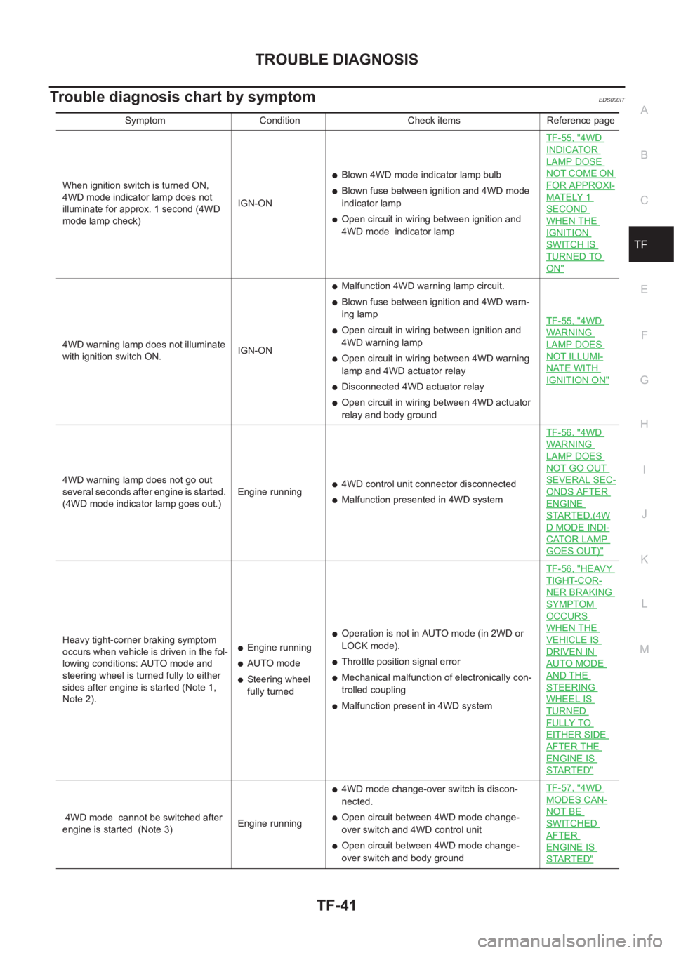
Trouble diagnosis chart by symptomEDS000IT
Symptom Condition Check items Reference page
When ignition switch is turned ON,
4WD mode indicator lamp does not
illuminate for approx. 1 second (4WD
mode lamp check)IGN-ON
●Blown 4WD mode indicator lamp bulb
●Blown fuse between ignition and 4WD mode
indicator lamp
●Open circuit in wiring between ignition and
4WD mode indicator lampTF-55, "
4WD
INDICATOR
LAMP DOSE
NOT COME ON
FOR APPROXI-
MATELY 1
SECOND
WHEN THE
IGNITION
SWITCH IS
TURNED TO
ON"
4WD warning lamp does not illuminate
with ignition switch ON.IGN-ON
●Malfunction 4WD warning lamp circuit.
●Blown fuse between ignition and 4WD warn-
ing lamp
●Open circuit in wiring between ignition and
4WD warning lamp
●Open circuit in wiring between 4WD warning
lamp and 4WD actuator relay
●Disconnected 4WD actuator relay
●Open circuit in wiring between 4WD actuator
relay and body groundTF-55, "
4WD
WARNING
LAMP DOES
NOT ILLUMI-
NATE WITH
IGNITION ON"
4WD warning lamp does not go out
several seconds after engine is started.
(4WD mode indicator lamp goes out.)Engine running●4WD control unit connector disconnected
●Malfunction presented in 4WD systemTF-56, "
4WD
WARNING
LAMP DOES
NOT GO OUT
SEVERAL SEC-
ONDS AFTER
ENGINE
STARTED.(4W
D MODE INDI-
CATOR LAMP
GOES OUT)"
Heavy tight-corner braking symptom
occurs when vehicle is driven in the fol-
lowing conditions: AUTO mode and
steering wheel is turned fully to either
sides after engine is started (Note 1,
Note 2).●Engine running
●AUTO mode
●Steering wheel
fully turned
●Operation is not in AUTO mode (in 2WD or
LOCK mode).
●Throttle position signal error
●Mechanical malfunction of electronically con-
trolled coupling
●Malfunction present in 4WD systemTF-56, "
HEAVY
TIGHT-COR-
NER BRAKING
SYMPTOM
OCCURS
WHEN THE
VEHICLE IS
DRIVEN IN
AUTO MODE
AND THE
STEERING
WHEEL IS
TURNED
FULLY TO
EITHER SIDE
AFTER THE
ENGINE IS
STARTED"
4WD mode cannot be switched after
engine is started (Note 3)Engine running
●4WD mode change-over switch is discon-
nected.
●Open circuit between 4WD mode change-
over switch and 4WD control unit
●Open circuit between 4WD mode change-
over switch and body groundTF-57, "
4WD
MODES CAN-
NOT BE
SWITCHED
AFTER
ENGINE IS
STARTED"
Page 2802 of 3833
![NISSAN X-TRAIL 2001 Service Repair Manual BRC-18
[4WD/ABS]
TROUBLE DIAGNOSIS
Trouble Diagnosis Chart by Symptom
EFS001BF
When ABS and 4WD warning lamps illuminate, perform self-diagnosis.
Symptom Condition Check items Reference page
4wd indic NISSAN X-TRAIL 2001 Service Repair Manual BRC-18
[4WD/ABS]
TROUBLE DIAGNOSIS
Trouble Diagnosis Chart by Symptom
EFS001BF
When ABS and 4WD warning lamps illuminate, perform self-diagnosis.
Symptom Condition Check items Reference page
4wd indic](/manual-img/5/57405/w960_57405-2801.png)
BRC-18
[4WD/ABS]
TROUBLE DIAGNOSIS
Trouble Diagnosis Chart by Symptom
EFS001BF
When ABS and 4WD warning lamps illuminate, perform self-diagnosis.
Symptom Condition Check items Reference page
4wd indicator lamp does not come on
for approximately 1 second when the
ignition switch is turned on.IGN-ON
●Blown drive mode indicator lamp bulb
●Blown fuse between ignition and drive mode
indicator lamp
●Open circuit of wiring between ignition and
drive mode indicator lampBRC-42
ABS warning lamp does not illuminate
with ignition ON. (ABS warning lamp
check)IGN-ON
●Blown ABS warning lamp bulb
●Blown fuse between ignition and ABS warning
lamp.
●Open circuit of wiring between ignition and
ABS warning lamp.
●Malfunction in ABS systemBRC-42
ABS warning lamp illuminates with
ignition ON, but does not illuminates
after a few seconds. (ABS warning
lamp has not illuminated.)IGN-ON●4WD/ABS control unit connector discon-
nected
●Malfunction in ABS systemBRC-42
4WD warning lamp does not illuminate
with ignition ON.IGN-ON
●Blown 4WD warning lamp bulb
●Blown fuse between ignition and 4WD warn-
ing lamp
●Open circuit in wire between ignition and 4WD
warning lamp
●Open circuit in wire between 4WD warning
lamp and 4WD actuator relay
●Disconnected 4WD actuator relay
●Open circuit in wire between 4WD actuator
relay and body groundBRC-43
4WD warning lamp does not go out
several seconds after engine is started.
(Drive mode indicator lamp goes out.)Engine running●4WD/ABS control unit connector discon-
nected
●Malfunction present in 4WD systemBRC-43
Heavy tight-corner braking symptom
occurs when vehicle is driven in the fol-
lowing conditions: AUTO mode and
steering wheel is turned fully to either
sides after engine is started (Note 1,
Note 2).●Engine run-
ning
●AUTO mode
●Steering
wheel fully
turned
●Operation is not in AUTO mode (in 2WD or
LOCK mode).
●Throttle position signal error
●Mechanical malfunction of electronically con-
trolled coupling
●Malfunction present in 4WD systemBRC-44
Drive modes cannot be switched after
engine is started.Engine running
●Drive mode change-over switch is discon-
nected.
●Open circuit between drive mode change-over
switch and 4WD /ABS control unit
●Open circuit between drive mode change-over
switch and body groundBRC-45
Vehicle running, 4WD warning lamp
flashes rapidly. (When it flashes for
Approx. One minute, then does not illu-
minate.) Rapid flashing: Two times
flashing per 1 secondEngine running
(to other than
2WD mode)Protection function was activated due to heavy
load to electronically controlled coupling. (4WD
system is not malfunctioning.)BRC-45
Page 3070 of 3833
BL-18
POWER DOOR LOCK SYSTEM
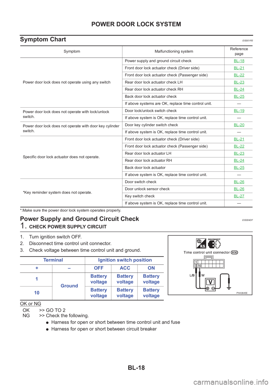
Symptom Chart
EIS001R5
*:Make sure the power door lock system operates properly.
Power Supply and Ground Circuit CheckEIS004DF
1. CHECK POWER SUPPLY CIRCUIT
1. Turn ignition switch OFF.
2. Disconnect time control unit connector.
3. Check voltage between time control unit and ground.
OK or NG
OK >> GO TO 2
NG >> Check the following.
●Harness for open or short between time control unit and fuse
●Harness for open or short between circuit breaker
Symptom Malfunctioning systemReference
page
Power door lock does not operate using any switchPower supply and ground circuit checkBL-18
Front door lock actuator check (Driver side)BL-21
Front door lock actuator check (Passenger side)BL-22
Rear door lock actuator check LH BL-23
Rear door lock actuator check RHBL-24
Back door lock actuator checkBL-25
If above systems are OK, replace time control unit. —
Power door lock does not operate with lock/unlock
switch.Door lock/unlock switch checkBL-19
If above system is OK, replace time control unit. —
Power door lock does not operate with door key cylinder
switch.Door key cylinder switch checkBL-20
If above system is OK, replace time control unit. —
Specific door lock actuator does not operate.Front door lock actuator check (Driver side)BL-21
Front door lock actuator check (Passenger side)BL-22
Rear door lock actuator LHBL-23
Rear door lock actuator RHBL-24
Back door lock actuatorBL-25
If above system is OK, replace time control unit. —
*Key reminder system does not operate.Door switch checkBL-26
Door unlock sensor checkBL-26
Key switch checkBL-27
If above system is OK, replace time control unit. —
Terminal Ignition switch position
+ – OFF ACC ON
1
GroundBattery
voltageBattery
voltageBattery
voltage
10Battery
voltageBattery
voltageBattery
voltage
PIIA3645E
Page 3142 of 3833
BL-90
NATS (NISSAN ANTI-THEFT SYSTEM)
*: When the vehicle is equipped with a dongle unit (RHD models), the security indicator blinks 6 times just after the ignition switch is
turned to ON. Then the security indicator lights up while the ignition key is in the “ON” position.
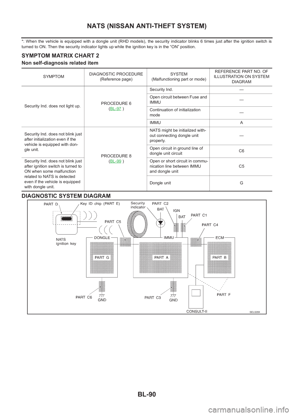
SYMPTOM MATRIX CHART 2
Non self-diagnosis related item
DIAGNOSTIC SYSTEM DIAGRAM
SYMPTOMDIAGNOSTIC PROCEDURE
(Reference page)SYSTEM
(Malfunctioning part or mode)REFERENCE PART NO. OF
ILLUSTRATION ON SYSTEM
DIAGRAM
Security Ind. does not light up.PROCEDURE 6
(BL-97
)Security Ind. —
Open circuit between Fuse and
IMMU—
Continuation of initialization
mode—
IMMU A
Security Ind. does not blink just
after initialization even if the
vehicle is equipped with don-
gle unit.
PROCEDURE 8
(BL-99
)NATS might be initialized with-
out connecting dongle unit
properly.—
Open circuit in ground line of
dongle unit circuitC6
Security Ind. does not blink just
after ignition switch is turned to
ON when some malfunction
related to NATS is detected
even if the vehicle is equipped
with dongle unit.Open or short circuit in commu-
nication line between IMMU
and dongle unitC5
Dongle unit G
SEL028X
Page 3143 of 3833
NATS (NISSAN ANTI-THEFT SYSTEM)
BL-91
C
D
E
F
G
H
J
K
L
MA
B
BL
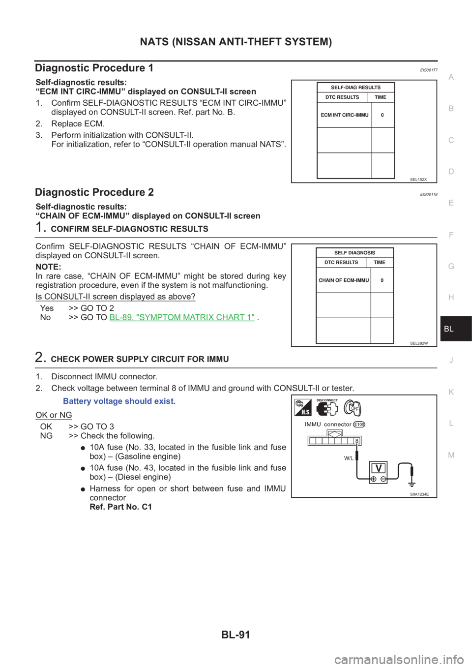
Diagnostic Procedure 1EIS001T7
Self-diagnostic results:
“ECM INT CIRC-IMMU” displayed on CONSULT-II screen
1. Confirm SELF-DIAGNOSTIC RESULTS “ECM INT CIRC-IMMU”
displayed on CONSULT-II screen. Ref. part No. B.
2. Replace ECM.
3. Perform initialization with CONSULT-II.
For initialization, refer to “CONSULT-II operation manual NATS”.
Diagnostic Procedure 2EIS001T8
Self-diagnostic results:
“CHAIN OF ECM-IMMU” displayed on CONSULT-II screen
1.CONFIRM SELF-DIAGNOSTIC RESULTS
Confirm SELF-DIAGNOSTIC RESULTS “CHAIN OF ECM-IMMU”
displayed on CONSULT-II screen.
NOTE:
In rare case, “CHAIN OF ECM-IMMU” might be stored during key
registration procedure, even if the system is not malfunctioning.
Is CONSULT-II screen displayed as above?
Ye s > > G O T O 2
No >> GO TO BL-89, "
SYMPTOM MATRIX CHART 1" .
2.CHECK POWER SUPPLY CIRCUIT FOR IMMU
1. Disconnect IMMU connector.
2. Check voltage between terminal 8 of IMMU and ground with CONSULT-II or tester.
OK or NG
OK >> GO TO 3
NG >> Check the following.
●10A fuse (No. 33, located in the fusible link and fuse
box) – (Gasoline engine)
●10A fuse (No. 43, located in the fusible link and fuse
box) – (Diesel engine)
●Harness for open or short between fuse and IMMU
connector
Ref. Part No. C1
SEL152X
SEL292W
Battery voltage should exist.
SIIA1234E
Page 3535 of 3833
![NISSAN X-TRAIL 2001 Service Repair Manual ILLUMINATION
LT-45
C
D
E
F
G
H
I
J
L
MA
B
LT
ILLUMINATIONPFP:27545
System Description EKS003C7
Power is supplied at all times
●through 10A fuse [No. 31, located in the fuse and fusible link box]
● NISSAN X-TRAIL 2001 Service Repair Manual ILLUMINATION
LT-45
C
D
E
F
G
H
I
J
L
MA
B
LT
ILLUMINATIONPFP:27545
System Description EKS003C7
Power is supplied at all times
●through 10A fuse [No. 31, located in the fuse and fusible link box]
●](/manual-img/5/57405/w960_57405-3534.png)
ILLUMINATION
LT-45
C
D
E
F
G
H
I
J
L
MA
B
LT
ILLUMINATIONPFP:27545
System Description EKS003C7
Power is supplied at all times
●through 10A fuse [No. 31, located in the fuse and fusible link box]
●to lighting switch terminal 11.
The lighting switch must be in the 1ST or 2ND position for illumination.
The following chart shows the power and ground connector terminals for the components included in the illu-
mination system.
Component Connector No. Power terminal Ground terminal
Headlamp washier switch M23 3 4
Headlamp aiming switch M24 3 4
Door mirror remote control
switchM26 10 1
ESP off switch M25 3 4
Hazard switch M51 7 8
4WD mode switch M39 4 3
Rear window defogger switch M50 5 6
A/C auto amp. M52 12 11
Combination meter
(LHD models)M46 56 66
Combination meter
(RHD models)M46 45 56
Audio M42 2 1
CD auto changer M82 34 35
Heater control panel M55 2 6
A/T device M58 3 4
Cigarette lighter M56 3 2
Heated seat switch LH
(LHD models)B131 5 6
Heated seat switch RH
(LHD models)B132 5 6
Heated seat switch LH
(RHD models)B35 5 6
Heated seat switch RH
(RHD models)B34 5 6
Page 3590 of 3833
DI-32
COMBINATION METERS (RHD MODELS)
SYMPTOM CHART
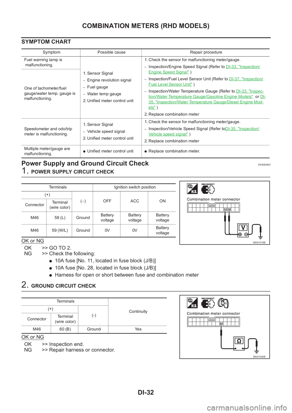
Power Supply and Ground Circuit CheckEKS0030O
1. POWER SUPPLY CIRCUIT CHECK
OK or NG
OK >> GO TO 2.
NG >> Check the following:
●10A fuse [No. 11, located in fuse block (J/B)]
●10A fuse [No. 28, located in fuse block (J/B)]
●Harness for open or short between fuse and combination meter
2. GROUND CIRCUIT CHECK
OK or NG
OK >> Inspection end.
NG >> Repair harness or connector.
Symptom Possible cause Repair procedure
Fuel warning lamp is
malfunctioning.
1. Sensor Signal
–Engine revolution signal
–Fuel gauge
–Water temp gauge
2. Unified meter control unit 1. Check the sensor for malfunctioning meter/gauge.
–Inspection/Engine Speed Signal (Refer to DI-33, "Inspection/
Engine Speed Signal" )
–Inspection/Fuel Level Sensor Unit (Refer to DI-37, "Inspection/
Fuel Level Sensor Unit" )
–Inspection/Water Temperature Gauge (Refer to DI-33, "Inspec-
tion/Water Temperature Gauge/Gasoline Engine Models" or DI-
35, "Inspection/Water Temperature Gauge/Diesel Engine Mod-
els" )
2. Replace combination meter One of tachometer/fuel
gauge/water temp. gauge is
malfunctioning.
Speedometer and odo/trip
meter is malfunctioning.1. Sensor Signal
–Vehicle speed signal
2. Unified meter control unit 1. Check the sensor for malfunctioning meter/gauge.–Inspection/Vehicle Speed Signal (Refer toDI-35, "Inspection/
Vehicle speed signal" )
2. Replace combination meter
Multiple meter/gauge are
malfunctioning.
●Unified meter control unit●Replace combination meter.
Terminals Ignition switch position
(+)
(−)OFF ACC ON
ConnectorTerminal
(wire color)
M46 58 (L) GroundBattery
voltageBattery
voltageBattery
voltage
M46 59 (W/L) Ground 0V 0VBattery
voltage
SKIA1019E
Te r m i n a l s
Continuity (+)
(-)
ConnectorTerminal
(wire color)
M46 60 (B) Ground Yes
SKIA1020E