2001 NISSAN X-TRAIL ATC-1
[x] Cancel search: ATC-1Page 765 of 3833
![NISSAN X-TRAIL 2001 Service Repair Manual REFRIGERANT PRESSURE SENSOR
EC-415
[QR25(WITH EURO-OBD)]
C
D
E
F
G
H
I
J
K
L
MA
EC
4.CHECK REFRIGERANT PRESSURE SENSOR GROUND CIRCUIT FOR OPEN AND SHORT
1. Turn ignition switch “OFF”.
2. Check har NISSAN X-TRAIL 2001 Service Repair Manual REFRIGERANT PRESSURE SENSOR
EC-415
[QR25(WITH EURO-OBD)]
C
D
E
F
G
H
I
J
K
L
MA
EC
4.CHECK REFRIGERANT PRESSURE SENSOR GROUND CIRCUIT FOR OPEN AND SHORT
1. Turn ignition switch “OFF”.
2. Check har](/manual-img/5/57405/w960_57405-764.png)
REFRIGERANT PRESSURE SENSOR
EC-415
[QR25(WITH EURO-OBD)]
C
D
E
F
G
H
I
J
K
L
MA
EC
4.CHECK REFRIGERANT PRESSURE SENSOR GROUND CIRCUIT FOR OPEN AND SHORT
1. Turn ignition switch “OFF”.
2. Check harness continuity between refrigerant pressure sensor terminal 1 and engine ground.
Refer to Wiring Diagram.
3. Also check harness for short to ground and short to power.
OK or NG
OK >> GO TO 6.
NG >> GO TO 5.
5.DETECT MALFUNCTIONING PART
Check the following.
●Harness connectors E61, F38
●Harness for open or short between ECM and refrigerant pressure sensor
>> Repair open circuit or short to ground or short to power in harness or connectors.
6.CHECK REFRIGERANT PRESSURE SENSOR INPUT SIGNAL CIRCUIT FOR OPEN AND SHORT
1. Disconnect ECM harness connector.
2. Check harness continuity between ECM terminal 83 and refrigerant pressure sensor terminal 2.
Refer to Wiring Diagram.
3. Also check harness for short to ground and short to power.
OK or NG
OK >> GO TO 8.
NG >> GO TO 7.
7.DETECT MALFUNCTIONING PART
Check the following.
●Harness connectors E61, F38
●Harness for open or short between ECM and refrigerant pressure sensor
>> Repair open circuit or short to ground or short to power in harness or connectors.
8.CHECK INTERMITTENT INCIDENT
Refer to EC-115, "
TROUBLE DIAGNOSIS FOR INTERMITTENT INCIDENT" .
OK or NG
OK >> Replace refrigerant pressure sensor.
NG >> Repair or replace.
Removal and InstallationEBS00MBQ
REFRIGERANT PRESSURE SENSOR
Refer to ATC-129, "REFRIGERANT LINES" . Continuity should exist.
Continuity should exist.
Page 1086 of 3833
![NISSAN X-TRAIL 2001 Service Repair Manual EC-736
[QR25(WITHOUT EURO-OBD)]
REFRIGERANT PRESSURE SENSOR
4. CHECK REFRIGERANT PRESSURE SENSOR GROUND CIRCUIT FOR OPEN AND SHORT
1. Turn ignition switch “OFF”.
2. Check harness continuity betwee NISSAN X-TRAIL 2001 Service Repair Manual EC-736
[QR25(WITHOUT EURO-OBD)]
REFRIGERANT PRESSURE SENSOR
4. CHECK REFRIGERANT PRESSURE SENSOR GROUND CIRCUIT FOR OPEN AND SHORT
1. Turn ignition switch “OFF”.
2. Check harness continuity betwee](/manual-img/5/57405/w960_57405-1085.png)
EC-736
[QR25(WITHOUT EURO-OBD)]
REFRIGERANT PRESSURE SENSOR
4. CHECK REFRIGERANT PRESSURE SENSOR GROUND CIRCUIT FOR OPEN AND SHORT
1. Turn ignition switch “OFF”.
2. Check harness continuity between refrigerant pressure sensor terminal 1 and engine ground.
Refer to Wiring Diagram.
3. Also check harness for short to ground and short to power.
OK or NG
OK >> GO TO 6.
NG >> GO TO 5.
5. DETECT MALFUNCTIONING PART
Check the following.
●Harness connectors E61, F38
●Harness for open or short between ECM and refrigerant pressure sensor
>> Repair open circuit or short to ground or short to power in harness or connectors.
6. CHECK REFRIGERANT PRESSURE SENSOR INPUT SIGNAL CIRCUIT FOR OPEN AND SHORT
1. Disconnect ECM harness connector.
2. Check harness continuity between ECM terminal 83 and refrigerant pressure sensor terminal 2.
Refer to Wiring Diagram.
3. Also check harness for short to ground and short to power.
OK or NG
OK >> GO TO 8.
NG >> GO TO 7.
7. DETECT MALFUNCTIONING PART
Check the following.
●Harness connectors E61, F38
●Harness for open or short between ECM and refrigerant pressure sensor
>> Repair open circuit or short to ground or short to power in harness or connectors.
8. CHECK INTERMITTENT INCIDENT
Refer to EC-115, "
TROUBLE DIAGNOSIS FOR INTERMITTENT INCIDENT" .
OK or NG
OK >> Replace refrigerant pressure sensor.
NG >> Repair or replace.
Removal and InstallationEBS00NL6
REFRIGERANT PRESSURE SENSOR
Refer to ATC-129, "REFRIGERANT LINES" . Continuity should exist.
Continuity should exist.
Page 1452 of 3833
![NISSAN X-TRAIL 2001 Service Repair Manual EC-1102
[QR20(WITH EURO-OBD)]
REFRIGERANT PRESSURE SENSOR
4. CHECK REFRIGERANT PRESSURE SENSOR GROUND CIRCUIT FOR OPEN AND SHORT
1. Turn ignition switch “OFF”.
2. Check harness continuity between NISSAN X-TRAIL 2001 Service Repair Manual EC-1102
[QR20(WITH EURO-OBD)]
REFRIGERANT PRESSURE SENSOR
4. CHECK REFRIGERANT PRESSURE SENSOR GROUND CIRCUIT FOR OPEN AND SHORT
1. Turn ignition switch “OFF”.
2. Check harness continuity between](/manual-img/5/57405/w960_57405-1451.png)
EC-1102
[QR20(WITH EURO-OBD)]
REFRIGERANT PRESSURE SENSOR
4. CHECK REFRIGERANT PRESSURE SENSOR GROUND CIRCUIT FOR OPEN AND SHORT
1. Turn ignition switch “OFF”.
2. Check harness continuity between refrigerant pressure sensor terminal 1 and engine ground.
Refer to Wiring Diagram.
3. Also check harness for short to ground and short to power.
OK or NG
OK >> GO TO 6.
NG >> GO TO 5.
5. DETECT MALFUNCTIONING PART
Check the following.
●Harness connectors E61, F38
●Harness for open or short between ECM and refrigerant pressure sensor
>> Repair open circuit or short to ground or short to power in harness or connectors.
6. CHECK REFRIGERANT PRESSURE SENSOR INPUT SIGNAL CIRCUIT FOR OPEN AND SHORT
1. Disconnect ECM harness connector.
2. Check harness continuity between ECM terminal 83 and refrigerant pressure sensor terminal 2.
Refer to Wiring Diagram.
3. Also check harness for short to ground and short to power.
OK or NG
OK >> GO TO 8.
NG >> GO TO 7.
7. DETECT MALFUNCTIONING PART
Check the following.
●Harness connectors E61, F38
●Harness for open or short between ECM and refrigerant pressure sensor
>> Repair open circuit or short to ground or short to power in harness or connectors.
8. CHECK INTERMITTENT INCIDENT
Refer to EC-847, "
TROUBLE DIAGNOSIS FOR INTERMITTENT INCIDENT" .
OK or NG
OK >> Replace refrigerant pressure sensor.
NG >> Repair or replace.
Removal and InstallationEBS00N2J
REFRIGERANT PRESSURE SENSOR
Refer to ATC-129, "REFRIGERANT LINES" . Continuity should exist.
Continuity should exist.
Page 1726 of 3833
![NISSAN X-TRAIL 2001 Service Repair Manual EC-1376
[QR20(WITHOUT EURO-OBD)]
REFRIGERANT PRESSURE SENSOR
4. CHECK REFRIGERANT PRESSURE SENSOR GROUND CIRCUIT FOR OPEN AND SHORT
1. Turn ignition switch “OFF”.
2. Check harness continuity be NISSAN X-TRAIL 2001 Service Repair Manual EC-1376
[QR20(WITHOUT EURO-OBD)]
REFRIGERANT PRESSURE SENSOR
4. CHECK REFRIGERANT PRESSURE SENSOR GROUND CIRCUIT FOR OPEN AND SHORT
1. Turn ignition switch “OFF”.
2. Check harness continuity be](/manual-img/5/57405/w960_57405-1725.png)
EC-1376
[QR20(WITHOUT EURO-OBD)]
REFRIGERANT PRESSURE SENSOR
4. CHECK REFRIGERANT PRESSURE SENSOR GROUND CIRCUIT FOR OPEN AND SHORT
1. Turn ignition switch “OFF”.
2. Check harness continuity between refrigerant pressure sensor terminal 1 and engine ground. Refer to
Wiring Diagram.
3. Also check harness for short to ground and short to power.
OK or NG
OK >> GO TO 6.
NG >> GO TO 5.
5. DETECT MALFUNCTIONING PART
Check the following.
●Harness connectors E61, F38
●Harness for open or short between ECM and refrigerant pressure sensor
>> Repair open circuit or short to ground or short to power in harness or connectors.
6. CHECK REFRIGERANT PRESSURE SENSOR INPUT SIGNAL CIRCUIT FOR OPEN AND SHORT
1. Disconnect ECM harness connector.
2. Check harness continuity between ECM terminal 83 and refrigerant pressure sensor terminal 2. Refer to
Wiring Diagram.
3. Also check harness for short to ground and short to power.
OK or NG
OK >> GO TO 8.
NG >> GO TO 7.
7. DETECT MALFUNCTIONING PART
Check the following.
●Harness connectors E61, F38
●Harness for open or short between ECM and refrigerant pressure sensor
>> Repair open circuit or short to ground or short to power in harness or connectors.
8. CHECK INTERMITTENT INCIDENT
Refer to EC-1192, "
TROUBLE DIAGNOSIS FOR INTERMITTENT INCIDENT" .
OK or NG
OK >> Replace refrigerant pressure sensor.
NG >> Repair or replace.
Removal and InstallationEBS00NAQ
REFRIGERANT PRESSURE SENSOR
Refer to ATC-129, "REFRIGERANT LINES" . Continuity should exist.
Continuity should exist.
Page 3277 of 3833

ATC-1
AUTOMATIC AIR CONDITIONER
J AIR CONDITIONER
CONTENTS
C
D
E
F
G
H
I
K
L
M
SECTION
A
B
AT C
AUTOMATIC AIR CONDITIONER
PRECAUTIONS .......................................................... 4
Precautions for Supplemental Restraint System
(SRS) “AIR BAG” and “SEAT BELT PRE-TEN-
SIONER” .................................................................. 4
Precautions for Working with HFC-134a (R-134a) ..... 4
General Refrigerant Precautions .............................. 5
Lubricant Precautions .............................................. 5
Precautions for Refrigerant Connection ................... 5
FEATURES OF NEW TYPE REFRIGERANT
CONNECTION ...................................................... 6
O-RING AND REFRIGERANT CONNECTION ..... 7
Precautions for Servicing Compressor ..................... 9
Precautions for Service Equipment ........................ 10
RECOVERY/RECYCLING EQUIPMENT ............ 10
ELECTRONIC LEAK DETECTOR ...................... 10
VACUUM PUMP ................................................. 10
MANIFOLD GAUGE SET .................................... 10
SERVICE HOSES ................................................ 11
SERVICE COUPLERS ......................................... 11
REFRIGERANT WEIGHT SCALE ....................... 11
CALIBRATING ACR4 WEIGHT SCALE ............... 11
CHARGING CYLINDER ...................................... 12
Precautions for Leak Detection Dye ....................... 12
IDENTIFICATION ................................................ 12
IDENTIFICATION LABEL FOR VEHICLE ........... 13
Wiring Diagrams and Trouble Diagnosis ................ 13
PREPARATION ......................................................... 14
Special Service Tools ............................................. 14
WITH GASOLINE ENGINE (CWV-615M COM-
PRESSOR) ......................................................... 14
WITH DIESEL ENGINE (DKV-11G COMPRES-
SOR) ................................................................... 14
HFC-134a (R-134a) Service Tools and Equipment ... 15
REFRIGERATION SYSTEM ..................................... 18
Refrigerant Cycle ................................................... 18
REFRIGERANT FLOW ....................................... 18
FREEZE PROTECTION (WITH GASOLINE
ENGINE: CWV-615M COMPRESSOR) .............. 18
Refrigerant System Protection ............................... 18
REFRIGERANT PRESSURE SENSOR (WITH GASOLINE ENGINE: CWV-615M COMPRES-
SOR) ................................................................... 18
DUAL-PRESSURE SWITCH (WITH DIESEL
ENGINE: DKV-11G COMPRESSOR) .................. 18
PRESSURE RELIEF VALVE (WITH GASOLINE
ENGINE: CWV-615M COMPRESSOR) .............. 18
V-6 Variable Displacement Compressor (With Gas-
oline Engine: CWV-615M Compressor) .................. 19
GENERAL INFORMATION ................................. 19
DESCRIPTION .................................................... 20
Component Layout ................................................. 23
LUBRICANT .............................................................. 24
Maintenance of Lubricant Quantity in Compressor ... 24
LUBRICANT ........................................................ 24
LUBRICANT RETURN OPERATION .................. 24
LUBRICANT ADJUSTING PROCEDURE FOR
COMPONENTS REPLACEMENT EXCEPT
COMPRESSOR .................................................. 25
LUBRICANT ADJUSTING PROCEDURE FOR
COMPRESSOR REPLACEMENT ....................... 25
AIR CONDITIONER CONTROL ............................... 27
Overview Air Conditioner LAN Control System ...... 27
System Construction .............................................. 27
OPERATION ........................................................ 27
TRANSMISSION DATA AND TRANSMISSION
ORDER ............................................................... 28
AIR MIX DOOR CONTROL (AUTOMATIC TEM-
PERATURE CONTROL) ..................................... 28
FAN SPEED CONTROL ...................................... 29
INTAKE DOOR CONTROL ................................. 29
OUTLET DOOR CONTROL ................................ 29
MAGNET CLUTCH CONTROL ........................... 29
SELF-DIAGNOSTIC SYSTEM ............................ 29
Overview of Control system .................................... 29
Control Operation ................................................... 30
DISPLAY SCREEN .............................................. 30
AUTO SWITCH ................................................... 30
TEMPERATURE DIAL (POTENTIO TEMPERA-
TURE CONTROL) ............................................... 30
A/C SWITCH ....................................................... 30
Page 3286 of 3833

ATC-10
PRECAUTIONS
●After compressor service operation, turn the compressor shaft by hand more than five turns in
both directions. This will equally distribute lubricant inside the compressor. After the compressor
is installed, let the engine idle and operate the compressor for one hour.
●After replacing the compressor magnet clutch, apply voltage to the new one and check for normal
operation.
Precautions for Service EquipmentEJS000T6
RECOVERY/RECYCLING EQUIPMENT
Be certain to follow the manufacturers instructions for machine operation and machine maintenance. Never
introduce any refrigerant other than that specified into the machine.
ELECTRONIC LEAK DETECTOR
Be certain to follow the manufacturer's instructions for tester operation and tester maintenance.
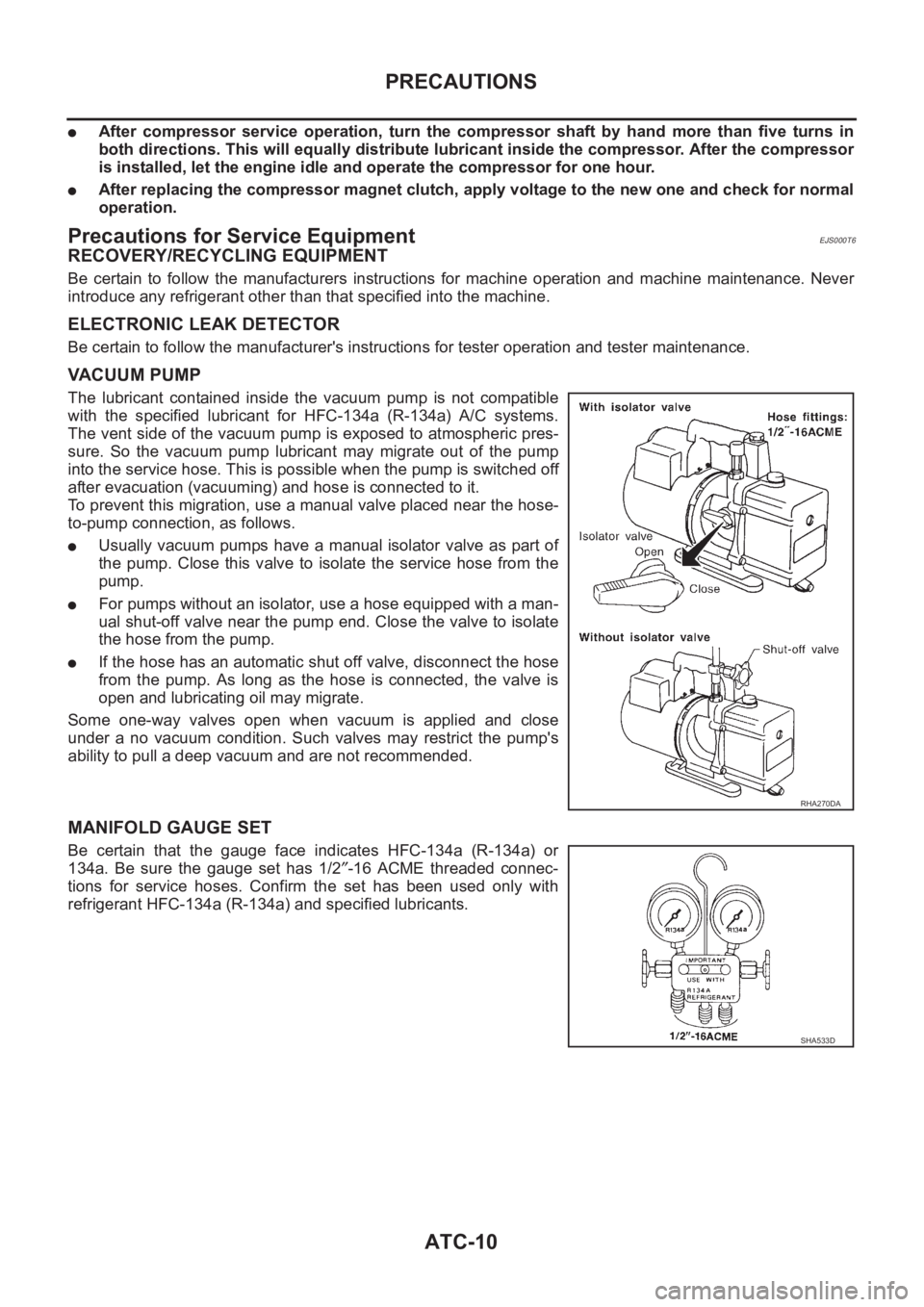
VACUUM PUMP
The lubricant contained inside the vacuum pump is not compatible
with the specified lubricant for HFC-134a (R-134a) A/C systems.
The vent side of the vacuum pump is exposed to atmospheric pres-
sure. So the vacuum pump lubricant may migrate out of the pump
into the service hose. This is possible when the pump is switched off
after evacuation (vacuuming) and hose is connected to it.
To prevent this migration, use a manual valve placed near the hose-
to-pump connection, as follows.
●Usually vacuum pumps have a manual isolator valve as part of
the pump. Close this valve to isolate the service hose from the
pump.
●For pumps without an isolator, use a hose equipped with a man-
ual shut-off valve near the pump end. Close the valve to isolate
the hose from the pump.
●If the hose has an automatic shut off valve, disconnect the hose
from the pump. As long as the hose is connected, the valve is
open and lubricating oil may migrate.
Some one-way valves open when vacuum is applied and close
under a no vacuum condition. Such valves may restrict the pump's
ability to pull a deep vacuum and are not recommended.
MANIFOLD GAUGE SET
Be certain that the gauge face indicates HFC-134a (R-134a) or
134a. Be sure the gauge set has 1/2″-16 ACME threaded connec-
tions for service hoses. Confirm the set has been used only with
refrigerant HFC-134a (R-134a) and specified lubricants.
RHA270DA
SHA533D
Page 3287 of 3833

PRECAUTIONS
ATC-11
C
D
E
F
G
H
I
K
L
MA
B
AT C
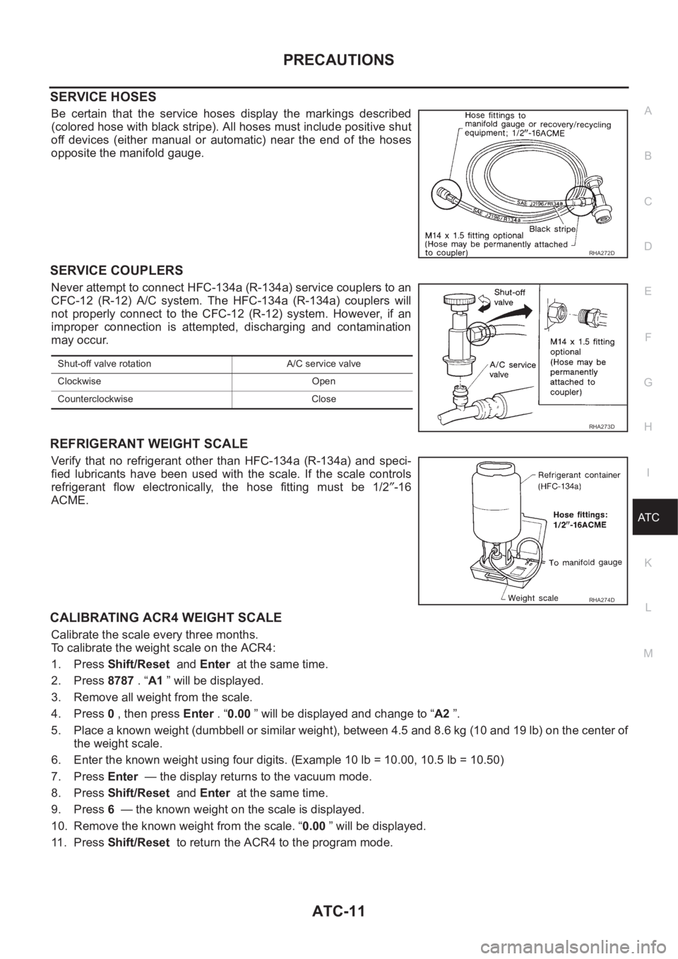
SERVICE HOSES
Be certain that the service hoses display the markings described
(colored hose with black stripe). All hoses must include positive shut
off devices (either manual or automatic) near the end of the hoses
opposite the manifold gauge.
SERVICE COUPLERS
Never attempt to connect HFC-134a (R-134a) service couplers to an
CFC-12 (R-12) A/C system. The HFC-134a (R-134a) couplers will
not properly connect to the CFC-12 (R-12) system. However, if an
improper connection is attempted, discharging and contamination
may occur.
REFRIGERANT WEIGHT SCALE
Verify that no refrigerant other than HFC-134a (R-134a) and speci-
fied lubricants have been used with the scale. If the scale controls
refrigerant flow electronically, the hose fitting must be 1/2″-16
ACME.
CALIBRATING ACR4 WEIGHT SCALE
Calibrate the scale every three months.
To calibrate the weight scale on the ACR4:
1. Press Shift/Reset and Enter at the same time.
2. Press 8787 . “A1 ” will be displayed.
3. Remove all weight from the scale.
4. Press 0 , then press Enter . “0.00 ” will be displayed and change to “A2 ”.
5. Place a known weight (dumbbell or similar weight), between 4.5 and 8.6 kg (10 and 19 lb) on the center of
the weight scale.
6. Enter the known weight using four digits. (Example 10 lb = 10.00, 10.5 lb = 10.50)
7. Press Enter — the display returns to the vacuum mode.
8. Press Shift/Reset and Enter at the same time.
9. Press 6 — the known weight on the scale is displayed.
10. Remove the known weight from the scale. “0.00 ” will be displayed.
11 . P r e s s Shift/Reset to return the ACR4 to the program mode.
RHA272D
Shut-off valve rotation A/C service valve
Clockwise Open
Counterclockwise Close
RHA273D
RHA274D
Page 3288 of 3833

ATC-12
PRECAUTIONS
CHARGING CYLINDER
Using a charging cylinder is not recommended. Refrigerant may be vented into air from cylinder's top valve
when filling the cylinder with refrigerant. Also, the accuracy of the cylinder is generally less than that of an
electronic scale or of quality recycle/recharge equipment.
Precautions for Leak Detection DyeEJS0027Z
●The A/C system contains a fluorescent leak detection dye used for locating refrigerant leaks. An ultraviolet
(UV) lamp is required to illuminate the dye when inspecting for leaks.
●Always wear fluorescence enhancing UV safety goggles to protect your eyes and enhance the visibility of
the fluorescent dye.
●The fluorescent dye leak detector is not a replacement for an electronic refrigerant leak detector. The fluo-
rescent dye leak detector should be used in conjunction with an electronic refrigerant leak detector to (J-
41995) pin-point refrigerant leaks.
●For your safety and your Customer's satisfaction, read and follow all manufacture's operating instructions
and precautions prior to performing the work.
●A compressor shaft seal should not be repaired because of dye seepage. The compressor shaft seal
should only be repaired after confirming the leak with an electronic refrigerant leak detector (J-41995).
●Always remove any remaining dye from the leak area after repairs are complete to avoid a misdiagnosis
during a future service.
●Do not allow dye to come into contact with painted body panels or interior components. If dye is spilled,
clean immediately with the approved dye cleaner. Fluorescent dye left on a surface for an extended period
of time cannot be removed.
●Do not spray the fluorescent dye cleaning agent on hot surfaces (engine exhaust manifold, etc.).
●Do not use more than one refrigerant dye bottle (1/4 ounce / 7.4 cc) per A/C system.
●Leak detection dyes for HFC-134a (R-134a) and CFC-12 (R12) A/C systems are different. Do not use
HFC-134a (R-134a) leak detection dye in CFC-12 (R-12) A/C system or CFC-12 (R-12) leak detector dye
in HFC-134a (R-134a) A/C systems or A/C system damage may result.
●The fluorescent properties of the dye will remain for over three (3) years unless a compressor malfunction
occurs.
IDENTIFICATION
NOTE:
Vehicles with factory installed fluorescent dye have a green label.
Vehicles without factory installed fluorescent dye have a blue label.