2001 NISSAN X-TRAIL washer fluid
[x] Cancel search: washer fluidPage 288 of 3833
![NISSAN X-TRAIL 2001 Service Repair Manual LU-8
[QR]
ENGINE OIL
c. After warming up the engine, check for engine oil leakage with running engine.
Changing Engine OilEBS00KO4
WARNING:
●Be careful not to burn yourself, as the engine oil is hot NISSAN X-TRAIL 2001 Service Repair Manual LU-8
[QR]
ENGINE OIL
c. After warming up the engine, check for engine oil leakage with running engine.
Changing Engine OilEBS00KO4
WARNING:
●Be careful not to burn yourself, as the engine oil is hot](/manual-img/5/57405/w960_57405-287.png)
LU-8
[QR]
ENGINE OIL
c. After warming up the engine, check for engine oil leakage with running engine.
Changing Engine OilEBS00KO4
WARNING:
●Be careful not to burn yourself, as the engine oil is hot.
●Prolonged and repeated contact with used engine oil may
cause skin cancer. Try to avoid direct skin contact with
used engine oil. If skin contact is made, wash thoroughly
with soap or hand cleaner as soon as possible.
1. Warm up engine, put vehicle horizontally and check for engine
oil leakage from engine components.
2. Stop engine and wait for 10 minutes.
3. Remove drain plug and oil filler cap.
4. Drain engine oil.
●Install drain plug and refill with new engine oil.
Engine oil specifications and viscosity:
●API grade SG, SH, SJ or SL.
●ILSAC grade GF-I, GF-II or GF-III
●ACEA 96-A2
●Refer to MA-16, "RECOMMENDED FLUIDS AND LUBRICANTS" for further detail.
Engine oil capacity (Approximate):
Unit: (lmp qt)
CAUTION:
●Be sure to clean drain plug and install with new washer.
●The refill capacity depends on the engine oil temperature and drain time. Use these specifica-
tions for reference only.
●Always use the dipstick to the determine when the proper amount of engine oil is in the engine.
5. Warm up engine and check area around drain plug and oil filter for engine oil leakage.
6. Stop engine and wait for 10 minutes.
7. Check engine oil level. Refer to LU-7, "
ENGINE OIL LEVEL" . Oil pressure switch:
: 12.3 - 17.2 N·m (1.25 - 1.75 kg-m, 9 - 12 ft-lb)
PBIC0250E
Drain and refillWith oil filter change Approximately 3.9 (3-3/8)
Without oil filter change Approximately 3.5 (3-1/8)
Dry engine (engine overhaul)Approximately 4.5 (4)
Oil pan drain plug:
: 29.4 - 39.2 N·m (3.0 - 4.0 kg-m, 22 - 28 ft-lb)
Page 299 of 3833
![NISSAN X-TRAIL 2001 Service Repair Manual ENGINE OIL
LU-19
[YD22DDTi]
C
D
E
F
G
H
I
J
K
L
MA
LUc. After warming up the engine, check for oil leakage with running engine.
Changing Engine OilEBS00B04
WARNING:
●Be careful not to burn yourself, NISSAN X-TRAIL 2001 Service Repair Manual ENGINE OIL
LU-19
[YD22DDTi]
C
D
E
F
G
H
I
J
K
L
MA
LUc. After warming up the engine, check for oil leakage with running engine.
Changing Engine OilEBS00B04
WARNING:
●Be careful not to burn yourself,](/manual-img/5/57405/w960_57405-298.png)
ENGINE OIL
LU-19
[YD22DDTi]
C
D
E
F
G
H
I
J
K
L
MA
LUc. After warming up the engine, check for oil leakage with running engine.
Changing Engine OilEBS00B04
WARNING:
●Be careful not to burn yourself, as the engine oil is hot.
●Prolonged and repeated contact with used engine oil may
cause skin cancer: try to avoid direct skin contact with
used engine oil. If skin contact is made, wash thoroughly
with soap or hand cleaner as soon as possible.
1. Warm up engine, put vehicle horizontally and check for engine
oil leakage from engine components.
2. Stop engine and wait for 10 minutes.
3. Remove drain plug and oil filler cap.
4. Drain engine oil.
●Install drain plug and refill with new engine oil.
Engine oil specification and viscosity:
●API grade CF-4.
●ACEA B1, B3, B4, B5
●Refer to MA-16, "RECOMMENDED FLUIDS AND LUBRI-
CANTS" .
Engine oil capacity (Approximate):
●The refill capacity depends on the engine oil temperature and drain time. Use these specifications for
reference only.
Always use the dipstick to the determine when the proper amount of engine oil is in the engine.
CAUTION:
●Be sure to clean drain plug and install with new washer.
●The refill capacity depends on the engine oil temperature and drain time. Use these specifica-
tions for reference only.
Always use the dipstick to the determine when the proper amount of engine oil is in the
engine.
5. Warm up engine and check area around drain plug and oil filter for engine oil leakage.
6. Stop engine and wait for 10 minutes.
7. Check engine oil level. Refer to LU-18, "
ENGINE OIL LEVEL AND MUDDINESS" . Oil pressure switch:
: 13.0 - 17.0 N·m (1.4 - 1.7 kg-m, 10 - 12 ft-lb)
PBIC0527E
Drain and refillWith oil filter change
5.2 (4-5/8 Imp qt)
Without oil filter change
4.9 (4-3/8 Imp qt)
Dry engine (engine overhaul)6.3 (5-1/2 Imp qt)
Oil pan drain plug:
: 29 - 39 N·m (3.0 - 4.0 kg-m, 22 - 29 ft-lb)
SBIA0122E
Page 336 of 3833
![NISSAN X-TRAIL 2001 Service Repair Manual CO-30
[YD22DDTi]
ENGINE COOLANT
REFILLING ENGINE COOLANT
1. Install reservoir tank, radiator drain plug and cylinder block drain plug.
●Apply sealant to the thread of cylinder block drain plug.
Use NISSAN X-TRAIL 2001 Service Repair Manual CO-30
[YD22DDTi]
ENGINE COOLANT
REFILLING ENGINE COOLANT
1. Install reservoir tank, radiator drain plug and cylinder block drain plug.
●Apply sealant to the thread of cylinder block drain plug.
Use](/manual-img/5/57405/w960_57405-335.png)
CO-30
[YD22DDTi]
ENGINE COOLANT
REFILLING ENGINE COOLANT
1. Install reservoir tank, radiator drain plug and cylinder block drain plug.
●Apply sealant to the thread of cylinder block drain plug.
Use Genuine Liquid Gasket or equivalent.
2. Fill radiator slowly with engine coolant until engine coolant spills
from the air relief plugs, then install air relief plugs.
CAUTION:
If the filling rate is too fast, this could lead to air being
mixed in the engine coolant. Be sure to fill the engine cool-
ant slowly according to the rate indicated above.
●Replace the copper washer of the air bleeding plug.
●Use genuine Nissan anti-freeze engine coolant or equiva-
lent mixed with water (distilled or demineralized).
Refer to MA-16, "
RECOMMENDED FLUIDS AND LUBRICANTS".
●Pour engine coolant through engine coolant filler neck slowly of less than 2 (1-3/4 lmp qt) a
minute to allow air in system to escape.
3. Fill reservoir tank to specified level.
4. Warm up engine to normal operating temperature without radia-
tor cap installed.
●If engine coolant overflows radiator filler hole, install
radiator cap.
5. Run engine at 3,000 rpm for 10 seconds and return to idle speed
with radiator cap installed.
●Repeat two or three times.
Watch engine coolant temperature gauge so as not to overheat
the engine.
6. Stop engine and cool down to less than approximately
50°C(122°F).
●Cool down using a fan to reduce the time.
●If necessary, refill radiator up to filler neck with engine coolant.
7. Refill reservoir tank to MAX level line with engine coolant.
SBIA0130E
Cylinder block drain plug:
: 7.8 - 11.8 N·m (0.8 -1.2 kg-m , 69 - 104 in-lb)
Air relief plug:
: 6.7 - 7.9 N·m (0.68 - 0.81 kg-m, 59 - 70 in-lb)
Engine coolant capacity (With reservoir tank):
9.5 (8-3/8 Imp qt)
SMA182B
Reservoir tank
: 0.6 (1/2 lmp qt)
SMA412B
Page 1969 of 3833

OPERATING CYLINDER
CL-11
D
E
F
G
H
I
J
K
L
MA
B
CL
OPERATING CYLINDERPFP:30620
Removal and InstallationECS008BC
REMOVAL
1. Drain clutch fluid.
CAUTION:
Do not spill clutch fluid onto painted surfaces. If it spills, wipe up immediately and wash the
affected area with water.
2. Remove clutch hose from the operating cylinder.
3. Remove operating cylinder mounting bolt and remove operating cylinder from vehicle.
INSTALLATION
Paying attention to the following items, install in the reverse order of removal.
●Install hose with care so that it will not be bent or twisted.
●After completing the procedure, bleed the clutch tube.
(Refer to CL-8, "
Air Bleeding Procedure" .)
Disassembly and AssemblyECS008BD
DISASSEMBLY
●Remove dust cover and push rod. Remove piston, piston cup, and piston spring from inside the cylinder
body.
INSPECTION AFTER DISASSEMBLY
Check for any of the conditions shown below. If any malfunction is found, replace the part concerned.
●Damage to cylinder inner surface or piston sliding surface. Foreign matter, wear, corrosion, or pinhole
●Settling of the spring
●Cracked or deformed dust cover
ASSEMBLY
1. Apply rubber lubricant to cylinder body inner surface and rubber grease to the piston cup and piston.
Insert piston assembly and piston spring into the cylinder body.
2. Apply rubber grease to dust cover and install push rod and dust cover.
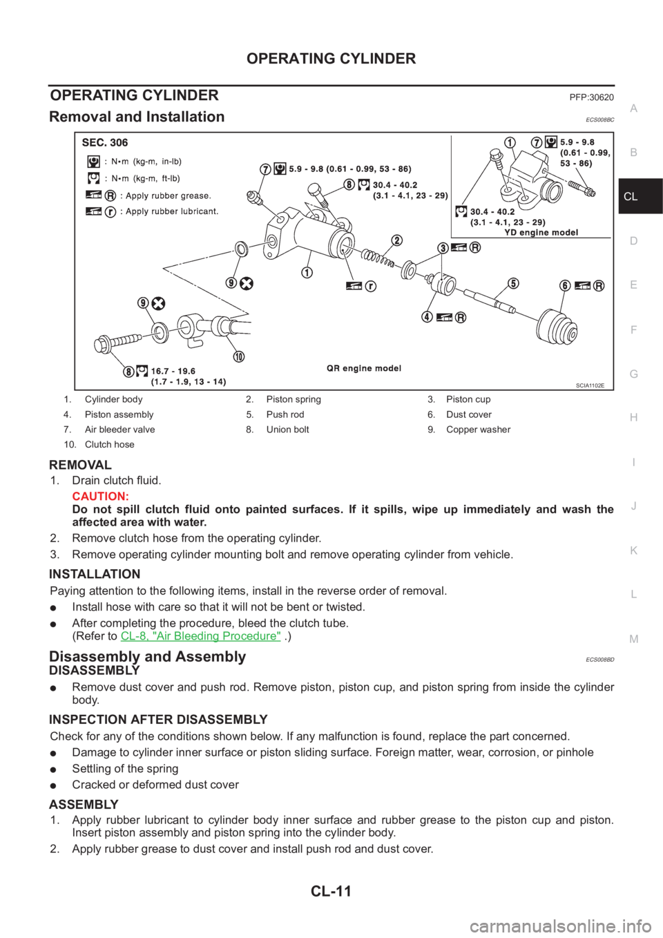
1. Cylinder body 2. Piston spring 3. Piston cup
4. Piston assembly 5. Push rod 6. Dust cover
7. Air bleeder valve 8. Union bolt 9. Copper washer
10. Clutch hose
SCIA1102E
Page 1970 of 3833

CL-12
CLUTCH PIPING
CLUTCH PIPING
PFP:30650
Removal and InstallationECS008BE
Carefully observe the following steps during clutch tube removal and installation.
●Do not spill clutch fluid onto painted surfaces. If it spills, wipe up immediately and wash the affected area
with water.
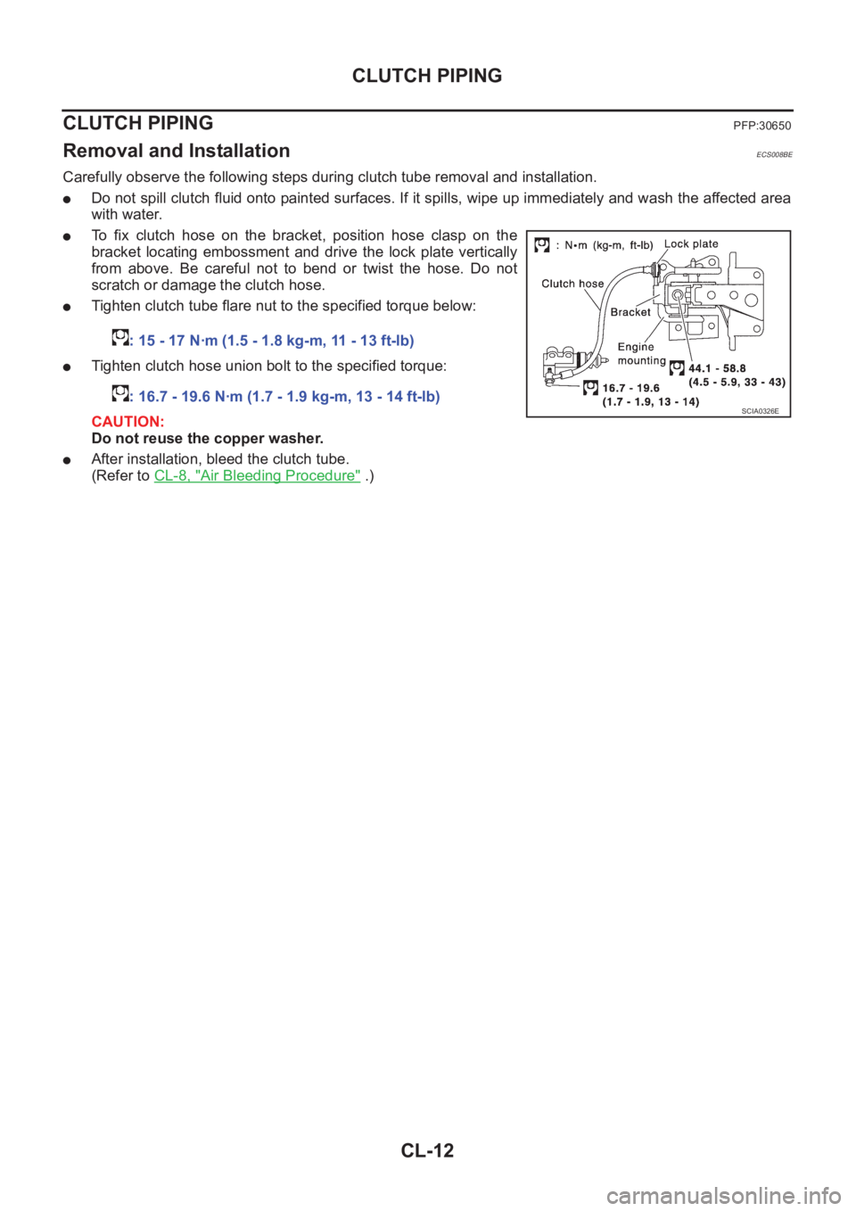
●To fix clutch hose on the bracket, position hose clasp on the
bracket locating embossment and drive the lock plate vertically
from above. Be careful not to bend or twist the hose. Do not
scratch or damage the clutch hose.
●Tighten clutch tube flare nut to the specified torque below:
●Tighten clutch hose union bolt to the specified torque:
CAUTION:
Do not reuse the copper washer.
●After installation, bleed the clutch tube.
(Refer to CL-8, "
Air Bleeding Procedure" .) : 15 - 17 N·m (1.5 - 1.8 kg-m, 11 - 13 ft-lb)
: 16.7 - 19.6 N·m (1.7 - 1.9 kg-m, 13 - 14 ft-lb)
SCIA0326E
Page 2082 of 3833

AT-4
Oil Channel ...........................................................424
Locations of Adjusting Shims, Needle Bearings,
Thrust Washers and Snap Rings ..........................425
DISASSEMBLY .......................................................426
Disassembly .........................................................426
REPAIR FOR COMPONENT PARTS ......................441
Manual Shaft ........................................................441
Oil Pump ...............................................................444
Control Valve Assembly ........................................448
Control Valve Upper Body ....................................457
Control Valve Lower Body ....................................461
Reverse Clutch .....................................................463
High Clutch ...........................................................466
Forward and Overrun Clutches ............................471
Low & Reverse Brake ...........................................476
Rear Internal Gear, Forward Clutch Hub and Over-
run Clutch Hub ......................................................479
Output Shaft, Idler Gear, Reduction Pinion Gear and
Bearing Retainer ...................................................483
Band Servo Piston Assembly ...............................488
Final Drive ............................................................493
ASSEMBLY .............................................................498
Assembly (1) .........................................................498
Adjustment (1) ......................................................499
Assembly (2) .........................................................504Adjustment (2) .......................................................510
Assembly (3) .........................................................514
SERVICE DATA AND SPECIFICATIONS (SDS) ....521
General Specifications ......................................... .521
Shift Schedule .......................................................521
Stall Revolution .....................................................522
Line Pressure ........................................................522
Control Valves .......................................................522
Accumulator ..........................................................523
Clutch and Brakes .................................................524
Final Drive .............................................................526
Planetary Carrier and Oil Pump ............................527
Input Shaft .............................................................528
Reduction Pinion Gear ..........................................528
Band Servo ...........................................................529
Output Shaft ..................................................
........529
Bearing Retainer ...................................................529
Total End Play .......................................................529
Reverse Clutch End Play ......................................530
Removal and Installation .......................................530
Shift Solenoid Valves ............................................530
Solenoid Valves ....................................................530
A/T Fluid Temperature Sensor ..............................531
Revolution Sensor .................................................531
Dropping Resistor .................................................531
Page 2085 of 3833

PRECAUTIONS
AT-7
D
E
F
G
H
I
J
K
L
MA
B
AT
●After performing each TROUBLE DIAGNOSIS, perform
“DTC (Diagnostic Trouble Code) CONFIRMATION PROCE-
DURE”.
The DTC should not be displayed in the “DTC CONFIRMA-
TION PROCEDURE” if the repair is completed.
●Before proceeding with disassembly, thoroughly clean the out-
side of the transaxle. It is important to prevent the internal parts
from becoming contaminated by dirt or other foreign matter.
●Disassembly should be done in a clean work area.
●Use lint-free cloth or towels for wiping parts clean. Common
shop rags can leave fibers that could interfere with the operation
of the transaxle.
●Place disassembled parts in order for easier and proper assembly.
●All parts should be carefully cleaned with a general purpose, non-flammable solvent before inspection or
reassembly.
●Gaskets, seals and O-rings should be replaced any time the transaxle is disassembled.
●It is very important to perform functional tests whenever they are indicated.
●The valve body contains precision parts and requires extreme care when parts are removed and serviced.
Place disassembled valve body parts in order for easier and proper assembly. Care will also prevent
springs and small parts from becoming scattered or lost.
●Properly installed valves, sleeves, plugs, etc. will slide along bores in valve body under their own weight.
●Before assembly, apply a coat of recommended ATF to all parts. Apply petroleum jelly to protect O-rings
and seals, or hold bearings and washers in place during assembly. Do not use grease.
●Extreme care should be taken to avoid damage to O-rings, seals and gaskets when assembling.
●After overhaul, refill the transaxle with new ATF.
●When the A/T drain plug is removed, only some of the fluid is drained. Old A/T fluid will remain in torque
converter and ATF cooling system.
Always follow the procedures under “Changing A/T Fluid” in the AT section when changing A/T fluid. Refer
to “Changing A/T Fluid”, AT-13, "
A/T FLUID" .
Service Notice or PrecautionsECS004Q3
FA I L - S A F E
The TCM has an electronic Fail-Safe (limp home mode). This allows the vehicle to be driven even if a major
electrical input/output device circuit is damaged.
Under Fail-Safe, the vehicle always runs in third gear, even with a shift lever position of “1”, “2” or “D”. The cus-
tomer may complain of sluggish or poor acceleration.
When the ignition key is turned “ON” following Fail-Safe operation, O/D OFF indicator lamp blinks for about 8
seconds. Refer to AT- 2 5 3 , "
SELF-DIAGNOSTIC PROCEDURE (WITHOUT CONSULT-II)" (EXCEPT FOR
EURO-OBD) or AT-51, "
TCM SELF-DIAGNOSTIC PROCEDURE (NO TOOLS)" (EURO-OBD).
The blinking of the O/D OFF indicator lamp for about 8 seconds will appear only once and be cleared. The
customer may resume normal driving conditions.
Always follow the “WORK FLOW”, refer to AT-262, "
Work Flow" (EXCEPT FOR Euro-OBD) or AT- 6 0 , "Work
Flow" (Euro-OBD).
The SELF-DIAGNOSIS results will be as follows:
●The first SELF-DIAGNOSIS will indicate damage to the vehicle speed sensor or the revolution sensor.
●During the next SELF-DIAGNOSIS, performed after checking the sensor, no damages will be indicated.
TORQUE CONVERTER SERVICE
The torque converter should be replaced under any of the following conditions:
●External leaks in the hub weld area.
●Converter hub is scored or damaged.
●Converter pilot is broken, damaged or fits poorly into crankshaft.
●Steel particles are found after flushing the cooler and cooler lines.
●Pump is damaged or steel particles are found in the converter.
●Vehicle has TCC shudder and/or no TCC apply. Replace only after all hydraulic and electrical diagnoses
have been made. (Converter clutch material may be glazed.)
SAT652J
Page 2164 of 3833
![NISSAN X-TRAIL 2001 Service Repair Manual AT-86
[EURO-OBD]
TROUBLE DIAGNOSIS — GENERAL DESCRIPTION
TROUBLE DIAGNOSIS — GENERAL DESCRIPTION
PFP:00000
Symptom ChartECS004QU
Numbers are arranged in order of inspection.
Perform inspections st NISSAN X-TRAIL 2001 Service Repair Manual AT-86
[EURO-OBD]
TROUBLE DIAGNOSIS — GENERAL DESCRIPTION
TROUBLE DIAGNOSIS — GENERAL DESCRIPTION
PFP:00000
Symptom ChartECS004QU
Numbers are arranged in order of inspection.
Perform inspections st](/manual-img/5/57405/w960_57405-2163.png)
AT-86
[EURO-OBD]
TROUBLE DIAGNOSIS — GENERAL DESCRIPTION
TROUBLE DIAGNOSIS — GENERAL DESCRIPTION
PFP:00000
Symptom ChartECS004QU
Numbers are arranged in order of inspection.
Perform inspections starting with number one and work up.
Symptom Condition Diagnostic ItemReference Page
EURO-OBD
Engine cannot start in “P” and “N”
positions.
AT- 2 11 , "
Engine Cannot Be Started
In “P” and “N” Position"
ON vehicle1. Ignition switch and starterPG-2, "
POWER SUPPLY
ROUTING",SC-20,
"STARTING SYSTEM"
2. Control cable adjustmentAT-416, "Control Cable
Adjustment"
3. PNP switchAT- 11 0 , "
DTC P0705
PARK/NEUTRAL POSI-
TION (PNP) SWITCH"
Engine starts in position other than
“N” and “P” positions.
AT- 2 11 , "
Engine Cannot Be Started
In “P” and “N” Position"
ON vehicle1. Control cable adjustmentAT-416, "
Control Cable
Adjustment"
2. PNP switchAT- 11 0 , "
DTC P0705
PARK/NEUTRAL POSI-
TION (PNP) SWITCH"
Transaxle noise in “P” and “N” posi-
tions.ON vehicle1. Fluid levelAT- 6 3 , "
FLUID LEVEL
CHECK"
2. Line pressure testAT- 6 7 , "Line Pressure Test"
3. Accelerator pedal position (APP) sensorAT-180, "
DTC P1705
ACCELERATOR PEDAL
POSITION (APP) SEN-
SOR"
4. Vehicle speed sensor·A/T (Revolution
sensor) and vehicle speed sensor·MTRAT-122, "
DTC P0720 VEHI-
CLE SPEED SENSOR·A/T
(REVOLUTION SEN-
SOR)",
AT-199, "
DTC VEHICLE
SPEED SENSOR MTR"
OFF vehicle5. Oil pumpAT-444, "
Oil Pump"
6. Torque converterAT-425, "
Locations of
Adjusting Shims, Needle
Bearings, Thrust Washers
and Snap Rings"
Vehicle moves when changing into
“P” position, or parking gear does
not disengage when shifted out of
“P” position.
AT- 2 1 2 , "
In “P” Position, Vehicle
Moves Forward Or Backward When
Pushed"
ON vehicle 1. Control cable adjustmentAT-416, "Control Cable
Adjustment"
OFF vehicle 2. Parking componentsAT-421, "
Components",AT-
441, "REPAIR FOR COM-
PONENT PARTS"
Vehicle runs in “N” position.
AT- 2 1 3 , "
In “N” Position, Vehicle
Moves"
ON vehicle 1. Control cable adjustmentAT-416, "Control Cable
Adjustment"
OFF vehicle2. Forward clutchAT-471, "
Forward and
Overrun Clutches"
3. Reverse clutchAT-463, "Reverse Clutch"
4. Overrun clutchAT-471, "Forward and
Overrun Clutches"