2001 NISSAN X-TRAIL air conditioning
[x] Cancel search: air conditioningPage 3 of 3833

GI-1
GENERAL INFORMATION
A GENERAL INFORMATION
CONTENTS
C
D
E
F
G
H
I
J
K
L
MB
GI
SECTION
GENERAL INFORMATION
PRECAUTIONS .......................................................... 3
Description ............................................................... 3
Precautions for Supplemental Restraint System
(SRS) “AIR BAG” and “SEAT BELT PRE-TEN-
SIONER” .................................................................. 3
Precautions for NATS (NISSAN ANTI-THEFT SYS-
TEM) ........................................................................ 3
General Precautions ................................................ 4
Precautions for All Mode 4 × 4 System .................... 5
Precautions for Three Way Catalyst ......................... 5
Precautions for Fuel ................................................. 5
GASOLINE ENGINE ............................................. 5
DIESEL ENGINE ................................................... 5
Precautions for Multiport Fuel Injection System or
Engine Control System ............................................ 6
Precautions for Turbocharger (If Equipped) ............. 6
Precautions for Hoses .............................................. 6
HOSE REMOVAL AND INSTALLATION ............... 6
HOSE CLAMPING ................................................ 7
Precautions for Engine Oils ...................................... 7
HEALTH PROTECTION PRECAUTIONS ............. 7
ENVIRONMENTAL PROTECTION PRECAU-
TIONS ................................................................... 7
Precautions for Air Conditioning ............................... 7
HOW TO USE THIS MANUAL ................................... 8
Description ............................................................... 8
Terms ....................................................................... 8
Units ......................................................................... 8
Contents ................................................................... 8
Components ............................................................. 8
SYMBOLS ............................................................. 9
How to Follow Trouble Diagnoses ............................ 9
DESCRIPTION ...................................................... 9
HOW TO FOLLOW TEST GROUPS IN TROU-
BLE DIAGNOSES ............................................... 10
HARNESS WIRE COLOR AND CONNECTOR
NUMBER INDICATION ........................................ 11
KEY TO SYMBOLS SIGNIFYING MEASURE-
MENTS OR PROCEDURES ............................... 12
How to Read Wiring Diagrams ............................... 14CONNECTOR SYMBOLS ................................... 14
SAMPLE/WIRING DIAGRAM - EXAMPL - .......... 15
DESCRIPTION .................................................... 16
Abbreviations .......................................................... 22
SERVICE INFORMATION FOR ELECTRICAL INCI-
DENT ......................................................................... 23
How to Perform Efficient Diagnosis for an Electrical
Incident ................................................................... 23
WORK FLOW ...................................................... 23
INCIDENT SIMULATION TESTS ........................ 23
CIRCUIT INSPECTION ....................................... 26
Control Units and Electrical Parts ........................
... 31
PRECAUTIONS .................................................. 31
CONSULT-II CHECKING SYSTEM .......................... 33
Description .............................................................. 33
Function and System Application ........................... 33
Nickel Metal Hydride Battery Replacement ............ 33
Checking Equipment .............................................. 34
CONSULT-II Data Link Connector (DLC) Circuit .... 34
INSPECTION PROCEDURE .............................. 34
LIFTING POINT ......................................................... 35
Special Service Tools ............................................. 35
Garage Jack and Safety Stand ............................... 35
2-pole Lift ................................................................ 36
Board-on Lift ........................................................... 37
TOW TRUCK TOWING ............................................. 38
Tow Truck Towing ................................................... 38
TOWING AN AUTOMATIC TRANSAXLE
MODEL WITH FOUR WHEELS ON GROUND ... 38
T O W I N G T H E V E H I C L E W I T H R E A R W H E E L S
R A I S E D ( W I T H F R O N T W H E E L S O N G R O U N D )
OR FRONT WHEELS RAISED ........................... 39
Vehicle Recovery (Freeing a stuck vehicle) ............ 39
TIGHTENING TORQUE OF STANDARD BOLTS .... 40
Tightening Torque Table ......................................... 40
IDENTIFICATION INFORMATION ............................ 41
Model Variation ....................................................... 41
IDENTIFICATION NUMBER ................................ 42
IDENTIFICATION PLATE .................................... 43
ENGINE SERIAL NUMBER ................................ 43
Page 9 of 3833
PRECAUTIONS
GI-7
C
D
E
F
G
H
I
J
K
L
MB
GI
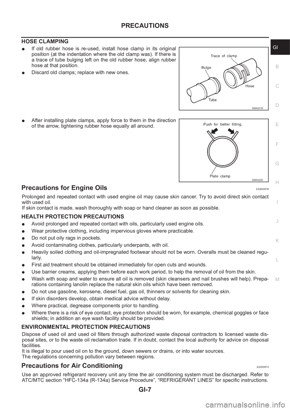
HOSE CLAMPING
●If old rubber hose is re-used, install hose clamp in its original
position (at the indentation where the old clamp was). If there is
a trace of tube bulging left on the old rubber hose, align rubber
hose at that position.
●Discard old clamps; replace with new ones.
●After installing plate clamps, apply force to them in the direction
of the arrow, tightening rubber hose equally all around.
Precautions for Engine OilsEAS000FW
Prolonged and repeated contact with used engine oil may cause skin cancer. Try to avoid direct skin contact
with used oil.
If skin contact is made, wash thoroughly with soap or hand cleaner as soon as possible.
HEALTH PROTECTION PRECAUTIONS
●Avoid prolonged and repeated contact with oils, particularly used engine oils.
●Wear protective clothing, including impervious gloves where practicable.
●Do not put oily rags in pockets.
●Avoid contaminating clothes, particularly underpants, with oil.
●Heavily soiled clothing and oil-impregnated footwear should not be worn. Overalls must be cleaned regu-
larly.
●First aid treatment should be obtained immediately for open cuts and wounds.
●Use barrier creams, applying them before each work period, to help the removal of oil from the skin.
●Wash with soap and water to ensure all oil is removed (skin cleansers and nail brushes will help). Prepa-
rations containing lanolin replace the natural skin oils which have been removed.
●Do not use gasoline, kerosene, diesel fuel, gas oil, thinners or solvents for cleaning skin.
●If skin disorders develop, obtain medical advice without delay.
●Where practical, degrease components prior to handling.
●Where there is a risk of eye contact, eye protection should be worn, for example, chemical goggles or face
shields; in addition an eye wash facility should be provided.
ENVIRONMENTAL PROTECTION PRECAUTIONS
Dispose of used oil and used oil filters through authorized waste disposal contractors to licensed waste dis-
posal sites, or to the waste oil reclamation trade. If in doubt, contact the local authority for advice on disposal
facilities.
It is illegal to pour used oil on to the ground, down sewers or drains, or into water sources.
The regulations concerning pollution vary between regions.
Precautions for Air Conditioning EAS000FX
Use an approved refrigerant recovery unit any time the air conditioning system must be discharged. Refer to
ATC/MTC section “HFC-134a (R-134a) Service Procedure”, “REFRIGERANT LINES” for specific instructions.
SMA021D
SMA022D
Page 93 of 3833
![NISSAN X-TRAIL 2001 Service Repair Manual TIMING CHAIN
EM-43
[QR]
C
D
E
F
G
H
I
J
K
L
MA
EM
5. Install timing chain and related parts.
●Install by lining up mating marks on each sprocket and timing
chain.
NOTE:
Before installing chain te](/manual-img/5/57405/w960_57405-92.png "NISSAN X-TRAIL 2001 Service Repair Manual TIMING CHAIN
EM-43
[QR]
C
D
E
F
G
H
I
J
K
L
MA
EM
5. Install timing chain and related parts.
●Install by lining up mating marks on each sprocket and timing
chain.
NOTE:
Before installing chain te")
TIMING CHAIN
EM-43
[QR]
C
D
E
F
G
H
I
J
K
L
MA
EM
5. Install timing chain and related parts.
●Install by lining up mating marks on each sprocket and timing
chain.
NOTE:
Before installing chain tensioner, it is possible to change the
position of mating mark on timing chain for that on each
sprocket for alignment.
CAUTION:
For the above reason, after the mating marks are aligned,
keep them aligned by holding them with a hand.
●Before and after installing chain tensioner, check again to
make sure that mating marks have not slipped.
●After installing chain tensioner, remove stopper pin, and make
sure that tensioner moves freely.
●To avoid skipped teeth, do not move crankshaft and camshaft
until front cover is installed.
6. Install front oil seal to front cover.
●Using a drift of 56 mm (2.20 in) dia, press oil seal in until it is
flush with front end surface of front cover.
CAUTION:
Be careful not to cause damage or burr to circumference of
oil seal.
7. Install front cover with the following procedure.
a. Install O-rings to cylinder head and cylinder block.
b. Apply liquid gasket to positions specified in the figure.
Use Genuine Liquid gasket or equivalent.
●Application instruction differs depending on the part.
c. Make sure that mating marks of timing chain and each sprocket
are still aligned. Then install front cover.
CAUTION:
●Do not let air conditioning and power steering piping
interfere with upper part of front cover.
●Be careful not to damage front oil seal by interference
with front end of crankshaft.
SBIA0265E
SBIA0266E
SBIA0267E
Page 178 of 3833
![NISSAN X-TRAIL 2001 Service Repair Manual EM-128
[YD22DDTi]
EXHAUST MANIFOLD AND TURBOCHARGER
14. Loosen exhaust manifold mounting nuts in the reverse order
specified in the figure.
15. Rotate the exhaust manifold and turbocharger ass](/manual-img/5/57405/w960_57405-177.png "NISSAN X-TRAIL 2001 Service Repair Manual EM-128
[YD22DDTi]
EXHAUST MANIFOLD AND TURBOCHARGER
14. Loosen exhaust manifold mounting nuts in the reverse order
specified in the figure.
15. Rotate the exhaust manifold and turbocharger ass")
EM-128
[YD22DDTi]
EXHAUST MANIFOLD AND TURBOCHARGER
14. Loosen exhaust manifold mounting nuts in the reverse order
specified in the figure.
15. Rotate the exhaust manifold and turbocharger assembly so that
the rear side (EGR cooler mounting side) faces upward. And
then pull out the assembly from between the engine and the air
conditioning piping.
CAUTION:
Be careful not to deform each turbocharger piping when
pulling out the assembly.
INSTALLATION
●When a stud bolt is pulled out, tighten it to the following torque:
●Tighten the exhaust manifold mounting nuts in the following procedure:
1. Tighten the nuts in the order specified in the figure.
2. Re-tighten the nuts 1 to 4.
3. Install the gasket so that the alignment protrusion faces the No.
4 port.
4. Install in reverse order of removal.
INSPECTION AFTER INSTALLATION
Start engine and raise engine speed to check no exhaust emission leaks.
JEM266G
: 18 - 21 N·m (1.8 - 2.2 kg-m, 13 - 15 ft-lb)
JEM266G
Page 351 of 3833
EC-1
ENGINE CONTROL SYSTEM
B ENGINE
CONTENTS
C
D
E
F
G
H
I
J
K
L
M
SECTION
A
EC
ENGINE CONTROL SYSTEM
QR25(WITH EURO-OBD)
INDEX FOR DTC ...................................................... 20
Alphabetical Index .................................................. 20
DTC No. Index ....................................................... 22
PRECAUTIONS ........................................................ 25
Precautions for Supplemental Restraint System
(SRS) “AIR BAG” and “SEAT BELT PRE-TEN-
SIONER” ................................................................ 25
On Board Diagnostic (OBD) System of Engine and
A/T .......................................................................... 25
Precaution .............................................................. 25
Wiring Diagrams and Trouble Diagnosis ................ 28
PREPARATION ......................................................... 29
Special Service Tools ............................................. 29
Commercial Service Tools ...................................... 29
ENGINE CONTROL SYSTEM .................................. 31
System Diagram ..................................................... 31
Vacuum Hose Drawing ........................................... 32
System Chart ......................................................... 33
Multiport Fuel Injection (MFI) System .................... 33
Electronic Ignition (EI) System ............................... 35
Air Conditioning Cut Control ................................... 36
Fuel Cut Control (at No Load and High Engine
Speed) .................................................................... 37
CAN Communication .............................................. 37
BASIC SERVICE PROCEDURE .............................. 38
Idle Speed and Ignition Timing Check .................... 38
Accelerator Pedal Released Position Learning ...... 39
Throttle Valve Closed Position Learning ................ 39
Idle Air Volume Learning ........................................ 39
Fuel Pressure Check .............................................. 42
ON BOARD DIAGNOSTIC (OBD) SYSTEM ............ 44
Introduction ............................................................ 44
Two Trip Detection Logic ........................................ 44
Emission-related Diagnostic Information ................ 45
NATS (Nissan Anti-theft System) ........................... 58
Malfunction Indicator (MI) ....................................... 58
OBD System Operation Chart ................................ 61
TROUBLE DIAGNOSIS ............................................ 67
Trouble Diagnosis Introduction ............................... 67DTC Inspection Priority Chart ................................. 70
Fail-safe Chart ........................................................ 71
Basic Inspection ..................................................... 73
Symptom Matrix Chart ............................................ 77
Engine Control Component Parts Location ............ 81
Circuit Diagram ....................................................... 85
ECM Harness Connector Terminal Layout ............. 87
ECM Terminals and Reference Value ..................
... 87
CONSULT-II Function ............................................. 94
Generic Scan Tool (GST) Function .......................104
CONSULT-II Reference Value in Data Monitor .....106
Major Sensor Reference Graph in Data Monitor
Mode .....................................................................109
TROUBLE DIAGNOSIS - SPECIFICATION VALUE ..111
Description .............................................................111
Testing Condition ...................................................111
Inspection Procedure .............................................111
Diagnostic Procedure ...........................................112
TROUBLE DIAGNOSIS FOR INTERMITTENT INCI-
DENT .......................................................................115
Description ............................................................115
Diagnostic Procedure ...........................................115
POWER SUPPLY CIRCUIT FOR ECM ...................116
Wiring Diagram .....................................................116
ECM Terminals and Reference Value ...................117
Diagnostic Procedure ...........................................117
Component Inspection ..........................................121
DTC U1000 CAN COMMUNICATION LINE ............122
Description ............................................................122
On Board Diagnosis Logic ....................................122
DTC Confirmation Procedure ...............................122
Wiring Diagram .....................................................123
Diagnostic Procedure ...........................................124
DTC P0011 IVT CONTROL .....................................125
Description ............................................................125
CONSULT-II Reference Value in Data Monitor Mode
.125
ECM Terminals and Reference Value ...................125
On Board Diagnosis Logic ....................................126
Page 356 of 3833

EC-6
DATA LINK CONNECTOR ......................................424
Wiring Diagram .....................................................424
EVAPORATIVE EMISSION SYSTEM .....................425
Description ............................................................425
Component Inspection ..........................................427
POSITIVE CRANKCASE VENTILATION ...............428
Description ............................................................428
Component Inspection ..........................................428
SERVICE DATA AND SPECIFICATIONS (SDS) ....430
Fuel Pressure .......................................................430
Idle Speed and Ignition Timing .............................430
Calculated Load Value ..........................................430
Mass Air Flow Sensor ...........................................430
Intake Air Temperature Sensor .............................430
Engine Coolant Temperature Sensor ...................430
Heated Oxygen Sensor 1 Heater .........................430
Heated Oxygen sensor 2 Heater ..........................430
Crankshaft Position Sensor (POS) .......................430
Camshaft Position Sensor (PHASE) ....................431
Throttle Control Motor ...........................................431
Injector ..................................................................431
Fuel Pump ............................................................431
QR25(WITHOUT EURO-OBD)
INDEX FOR DTC .....................................................432
Alphabetical Index ................................................432
DTC No. Index ......................................................433
PRECAUTIONS .......................................................435
Precautions for Supplemental Restraint System
(SRS) “AIR BAG” and “SEAT BELT PRE-TEN-
SIONER” ...............................................................435
On Board Diagnostic (OBD) System of Engine and
A/T ........................................................................435
Precaution ............................................................435
Wiring Diagrams and Trouble Diagnosis ..............438
PREPARATION .......................................................439
Special Service Tools ...........................................439
Commercial Service Tools ....................................439
ENGINE CONTROL SYSTEM ................................441
System Diagram ...................................................441
Vacuum Hose Drawing .........................................442
System Chart ........................................................443
Multiport Fuel Injection (MFI) System ...................443
Electronic Ignition (EI) System .............................445
Air Conditioning Cut Control .................................446
Fuel Cut Control (at No Load and High Engine
Speed) ..................................................................447
CAN Communication ............................................447
BASIC SERVICE PROCEDURE .............................448
Idle Speed and Ignition Timing Check ..................448
Accelerator Pedal Released Position Learning ....449
Throttle Valve Closed Position Learning ...............449
Idle Air Volume Learning ......................................450
Fuel Pressure Check ............................................452
ON BOARD DIAGNOSTIC (OBD) SYSTEM ..........454
Introduction ...........................................................454
Two Trip Detection Logic ......................................454
Emission-related Diagnostic Information ..............454NATS (Nissan Anti-theft System) ..........................456
Malfunction Indicator (MI) .....................................457
TROUBLE DIAGNOSIS ..........................................460
Trouble Diagnosis Introduction .............................460
DTC Inspection Priority Chart ...............................463
Fail-safe Chart ......................................................464
Basic Inspection ....................................................465
Symptom Matrix Chart ..........................................469
Engine Control Component Parts Location ...........473
Circuit Diagram .....................................................477
ECM Harness Connector Terminal Layout ............479
ECM Terminals and Reference Value ...................479
CONSULT-II Function ...........................................486
CONSULT-II Reference Value in Data Monitor .....496
Major Sensor Reference Graph in Data Monitor
Mode .....................................................................499
TROUBLE DIAGNOSIS - SPECIFICATION VALUE .502
Description ............................................................502
Testing Condition ..................................................502
Inspection Procedure ........................................... .502
Diagnostic Procedure ............................................503
TROUBLE DIAGNOSIS FOR INTERMITTENT INCI-
DENT .......................................................................506
Description ............................................................506
Diagnostic Procedure ............................................506
POWER SUPPLY CIRCUIT FOR ECM ...................507
Wiring Diagram .....................................................507
ECM Terminals and Reference Value ...................508
Diagnostic Procedure ............................................508
Component Inspection ..........................................512
DTC U1000 CAN COMMUNICATION LINE ............513
Description ............................................................513
On Board Diagnosis Logic ....................................513
DTC Confirmation Procedure ................................513
Wiring Diagram .....................................................514
Diagnostic Procedure ............................................515
DTC P0102, P0103 MAF SENSOR .........................516
Component Description ........................................516
CONSULT-II Reference Value in Data Monitor Mode
.516
ECM Terminals and Reference Value ...................516
On Board Diagnosis Logic ....................................516
DTC Confirmation Procedure ................................517
Wiring Diagram .....................................................519
Diagnostic Procedure ............................................520
Component Inspection ..........................................522
Removal and Installation .......................................522
DTC P0117, P0118 ECT SENSOR ..........................523
Component Description ........................................523
On Board Diagnosis Logic ....................................523
DTC Confirmation Procedure ................................524
Wiring Diagram .....................................................525
Diagnostic Procedure ............................................526
Component Inspection ..........................................527
Removal and Installation .......................................527
DTC P0122, P0123 TP SENSOR ............................528
Component Description ........................................528
CONSULT-II Reference Value in Data Monitor Mode
.528
Page 360 of 3833
EC-10
Injector ..................................................................752
Fuel Pump ............................................................752
QR20(WITH EURO-OBD)
INDEX FOR DTC .....................................................753
Alphabetical Index ................................................753
DTC No. Index ......................................................755
PRECAUTIONS .......................................................757
Precautions for Supplemental Restraint System
(SRS) “AIR BAG” and “SEAT BELT PRE-TEN-
SIONER” ...............................................................757
On Board Diagnostic (OBD) System of Engine and
A/T ........................................................................757
Precaution ............................................................757
Wiring Diagrams and Trouble Diagnosis ..............760
PREPARATION .......................................................761
Special Service Tools ...........................................761
Commercial Service Tools ....................................761
ENGINE CONTROL SYSTEM ................................763
System Diagram ...................................................763
Vacuum Hose Drawing .........................................764
System Chart ........................................................765
Multiport Fuel Injection (MFI) System ...................765
Electronic Ignition (EI) System .............................768
Air Conditioning Cut Control .................................768
Fuel Cut Control (at No Load and High Engine
Speed) ..................................................................769
CAN Communication ............................................769
BASIC SERVICE PROCEDURE .............................771
Idle Speed and Ignition Timing Check ..................771
Accelerator Pedal Released Position Learning ....772
Throttle Valve Closed Position Learning ...............772
Idle Air Volume Learning ......................................772
Fuel Pressure Check ............................................775
ON BOARD DIAGNOSTIC (OBD) SYSTEM ..........777
Introduction ...........................................................777
Two Trip Detection Logic ......................................777
Emission-related Diagnostic Information ..............778
NATS (Nissan Anti-theft System) ..........................790
Malfunction Indicator (MI) .....................................790
OBD System Operation Chart ..............................793
TROUBLE DIAGNOSIS ..........................................799
Trouble Diagnosis Introduction .............................799
DTC Inspection Priority Chart ...............................802
Fail-safe Chart ......................................................803
Basic Inspection ...................................................805
Symptom Matrix Chart ..........................................809
Engine Control Component Parts Location ..........813
Circuit Diagram .....................................................817
ECM Harness Connector Terminal Layout ...........819
ECM Terminals and Reference Value ...................819
CONSULT-II Function ...........................................826
Generic Scan Tool (GST) Function .......................836
CONSULT-II Reference Value in Data Monitor .....838
Major Sensor Reference Graph in Data Monitor
Mode .....................................................................840
TROUBLE DIAGNOSIS - SPECIFICATION VALUE .843
Description ............................................................843Testing Condition ..................................................843
Inspection Procedure ........................................... .843
Diagnostic Procedure ............................................844
TROUBLE DIAGNOSIS FOR INTERMITTENT INCI-
DENT .......................................................................847
Description ............................................................847
Diagnostic Procedure ............................................847
POWER SUPPLY CIRCUIT FOR ECM ...................848
Wiring Diagram .....................................................848
ECM Terminals and Reference Value ...................849
Diagnostic Procedure ............................................849
Component Inspection ..........................................853
DTC U1000 CAN COMMUNICATION LINE ............854
Description ............................................................854
On Board Diagnosis Logic ....................................854
DTC Confirmation Procedure ................................854
Wiring Diagram .....................................................855
Diagnostic Procedure ............................................856
DTC P0011 IVT CONTROL .....................................857
Description ............................................................857
CONSULT-II Reference Value in Data Monitor Mode
.857
ECM Terminals and Reference Value ...................857
On Board Diagnosis Logic ....................................858
DTC Confirmation Procedure ................................858
Diagnostic Procedure ............................................859
DTC P0031, P0032 HO2S1 HEATER ......................860
Description ............................................................860
CONSULT-II Reference Value in Data Monitor Mode
.860
ECM Terminals and Reference Value ...................860
On Board Diagnosis Logic ....................................861
DTC Confirmation Procedure ................................861
Wiring Diagram .....................................................862
Diagnostic Procedure ............................................863
Component Inspection ..........................................864
Removal and Installation .......................................864
DTC P0037, P0038 HO2S2 HEATER .....................
.865
Description ............................................................865
CONSULT-II Reference Value in Data Monitor Mode
.865
ECM Terminals and Reference Value ...................865
On Board Diagnosis Logic ....................................866
DTC Confirmation Procedure ................................866
Wiring Diagram .....................................................867
Diagnostic Procedure ............................................868
Component Inspection ..........................................869
Removal and Installation .......................................869
DTC P0102, P0103 MAF SENSOR .........................870
Component Description ........................................870
CONSULT-II Reference Value in Data Monitor Mode
.870
ECM Terminals and Reference Value ...................870
On Board Diagnosis Logic ....................................870
DTC Confirmation Procedure ................................871
Wiring Diagram .....................................................872
Diagnostic Procedure ............................................873
Component Inspection ..........................................874
Removal and Installation .......................................875
Page 364 of 3833

EC-14
Component Inspection .........................................1097
Removal and Installation .....................................1098
REFRIGERANT PRESSURE SENSOR .................1099
Component Description .......................................1099
ECM Terminals and Reference Value ..................1099
Wiring Diagram ....................................................11 0 0
Diagnostic Procedure ..........................................11 0 1
Removal and Installation .....................................11 0 2
ELECTRICAL LOAD SIGNAL ...............................110 3
CONSULT-II Reference Value in Data Monitor Mode
11 0 3
ECM Terminals and Reference Value ..................11 0 3
Wiring Diagram ....................................................11 0 4
Diagnostic Procedure ..........................................11 0 6
DATA LINK CONNECTOR .....................................1111
Wiring Diagram ....................................................1111
EVAPORATIVE EMISSION SYSTEM ....................111 2
Description ...........................................................111 2
Component Inspection .........................................111 4
POSITIVE CRANKCASE VENTILATION ..............111 5
Description ...........................................................111 5
Component Inspection .........................................111 5
SERVICE DATA AND SPECIFICATIONS (SDS) ...111 7
Fuel Pressure ......................................................111 7
Idle Speed and Ignition Timing ............................111 7
Calculated Load Value .........................................111 7
Mass Air Flow Sensor ..........................................111 7
Intake Air Temperature Sensor ............................111 7
Engine Coolant Temperature Sensor ..................111 7
Heated Oxygen Sensor 1 Heater ........................111 7
Heated Oxygen sensor 2 Heater .........................111 7
Crankshaft Position Sensor (POS) ......................111 7
Camshaft Position Sensor (PHASE) ...................111 7
Throttle Control Motor ..........................................111 8
Injector .................................................................111 8
Fuel Pump ...........................................................111 8
QR20(WITHOUT EURO-OBD)
INDEX FOR DTC ....................................................111 9
Alphabetical Index ...............................................111 9
DTC No. Index .....................................................11 2 0
PRECAUTIONS ......................................................112 1
Precautions for Supplemental Restraint System
(SRS) “AIR BAG” and “SEAT BELT PRE-TEN-
SIONER” ..............................................................11 2 1
On Board Diagnostic (OBD) System of Engine and
A/T .......................................................................11 2 1
Precaution ...........................................................11 2 1
Wiring Diagrams and Trouble Diagnosis .............11 2 4
PREPARATION ......................................................112 5
Special Service Tools .......................................... 11 2 5
Commercial Service Tools ...................................11 2 5
ENGINE CONTROL SYSTEM ...............................112 7
System Diagram ..................................................11 2 7
Vacuum Hose Drawing ........................................11 2 8
System Chart .......................................................11 2 9
Multiport Fuel Injection (MFI) System ..................11 2 9
Electronic Ignition (EI) System ............................11 3 2Air Conditioning Cut Control ................................11 3 2
Fuel Cut Control (at No Load and High Engine
Speed) .................................................................11 3 3
CAN Communication ...........................................11 3 3
BASIC SERVICE PROCEDURE ............................11 35
Idle Speed and Ignition Timing Check .................11 3 5
Accelerator Pedal Released Position Learning ....11 3 6
Throttle Valve Closed Position Learning ..............11 3 6
Idle Air Volume Learning ......................................11 3 7
Fuel Pressure Check ...........................................11 3 9
ON BOARD DIAGNOSTIC (OBD) SYSTEM ..........11 41
Introduction ..........................................................11 4 1
Two Trip Detection Logic ......................................11 4 1
Emission-related Diagnostic Information .............11 4 1
NATS (Nissan Anti-theft System) .........................11 4 3
Malfunction Indicator (MI) ....................................11 4 4
TROUBLE DIAGNOSIS .........................................11 47
Trouble Diagnosis Introduction ............................11 4 7
DTC Inspection Priority Chart ..............................11 5 0
Fail-safe Chart .....................................................11 5 1
Basic Inspection ...................................................11 5 2
Symptom Matrix Chart .........................................11 5 6
Engine Control Component Parts Location ..........11 6 0
Circuit Diagram ....................................................11 6 4
ECM Harness Connector Terminal Layout ...........11 6 6
ECM Terminals and Reference Value ..................11 6 6
CONSULT-II Function ..........................................
11 7 3
CONSULT-II Reference Value in Data Monitor ....11 8 2
Major Sensor Reference Graph in Data Monitor
Mode ....................................................................11 8 5
TROUBLE DIAGNOSIS - SPECIFICATION VALUE 11 88
Description ...........................................................11 8 8
Testing Condition .................................................11 8 8
Inspection Procedure ........................................... 11 8 8
Diagnostic Procedure ........................................... 11 8 9
TROUBLE DIAGNOSIS FOR INTERMITTENT INCI-
DENT ......................................................................11 92
Description ...........................................................11 9 2
Diagnostic Procedure ........................................... 11 9 2
POWER SUPPLY CIRCUIT FOR ECM ..................11 93
Wiring Diagram ....................................................11 9 3
ECM Terminals and Reference Value ..................11 9 4
Diagnostic Procedure ........................................... 11 9 4
Component Inspection .........................................11 9 8
DTC U1000 CAN COMMUNICATION LINE ...........11 99
Description ...........................................................11 9 9
On Board Diagnosis Logic ...................................11 9 9
DTC Confirmation Procedure ...............................11 9 9
Wiring Diagram ....................................................1200
Diagnostic Procedure ........................................... 1201
DTC P0102, P0103 MAF SENSOR ........................1202
Component Description .......................................1202
CONSULT-II Reference Value in Data Monitor Mode
1202
ECM Terminals and Reference Value ..................1202
On Board Diagnosis Logic ...................................1203
DTC Confirmation Procedure ...............................1203
Wiring Diagram ....................................................1205
Diagnostic Procedure ........................................... 1206