2001 NISSAN X-TRAIL checking oil
[x] Cancel search: checking oilPage 3 of 3833

GI-1
GENERAL INFORMATION
A GENERAL INFORMATION
CONTENTS
C
D
E
F
G
H
I
J
K
L
MB
GI
SECTION
GENERAL INFORMATION
PRECAUTIONS .......................................................... 3
Description ............................................................... 3
Precautions for Supplemental Restraint System
(SRS) “AIR BAG” and “SEAT BELT PRE-TEN-
SIONER” .................................................................. 3
Precautions for NATS (NISSAN ANTI-THEFT SYS-
TEM) ........................................................................ 3
General Precautions ................................................ 4
Precautions for All Mode 4 × 4 System .................... 5
Precautions for Three Way Catalyst ......................... 5
Precautions for Fuel ................................................. 5
GASOLINE ENGINE ............................................. 5
DIESEL ENGINE ................................................... 5
Precautions for Multiport Fuel Injection System or
Engine Control System ............................................ 6
Precautions for Turbocharger (If Equipped) ............. 6
Precautions for Hoses .............................................. 6
HOSE REMOVAL AND INSTALLATION ............... 6
HOSE CLAMPING ................................................ 7
Precautions for Engine Oils ...................................... 7
HEALTH PROTECTION PRECAUTIONS ............. 7
ENVIRONMENTAL PROTECTION PRECAU-
TIONS ................................................................... 7
Precautions for Air Conditioning ............................... 7
HOW TO USE THIS MANUAL ................................... 8
Description ............................................................... 8
Terms ....................................................................... 8
Units ......................................................................... 8
Contents ................................................................... 8
Components ............................................................. 8
SYMBOLS ............................................................. 9
How to Follow Trouble Diagnoses ............................ 9
DESCRIPTION ...................................................... 9
HOW TO FOLLOW TEST GROUPS IN TROU-
BLE DIAGNOSES ............................................... 10
HARNESS WIRE COLOR AND CONNECTOR
NUMBER INDICATION ........................................ 11
KEY TO SYMBOLS SIGNIFYING MEASURE-
MENTS OR PROCEDURES ............................... 12
How to Read Wiring Diagrams ............................... 14CONNECTOR SYMBOLS ................................... 14
SAMPLE/WIRING DIAGRAM - EXAMPL - .......... 15
DESCRIPTION .................................................... 16
Abbreviations .......................................................... 22
SERVICE INFORMATION FOR ELECTRICAL INCI-
DENT ......................................................................... 23
How to Perform Efficient Diagnosis for an Electrical
Incident ................................................................... 23
WORK FLOW ...................................................... 23
INCIDENT SIMULATION TESTS ........................ 23
CIRCUIT INSPECTION ....................................... 26
Control Units and Electrical Parts ........................
... 31
PRECAUTIONS .................................................. 31
CONSULT-II CHECKING SYSTEM .......................... 33
Description .............................................................. 33
Function and System Application ........................... 33
Nickel Metal Hydride Battery Replacement ............ 33
Checking Equipment .............................................. 34
CONSULT-II Data Link Connector (DLC) Circuit .... 34
INSPECTION PROCEDURE .............................. 34
LIFTING POINT ......................................................... 35
Special Service Tools ............................................. 35
Garage Jack and Safety Stand ............................... 35
2-pole Lift ................................................................ 36
Board-on Lift ........................................................... 37
TOW TRUCK TOWING ............................................. 38
Tow Truck Towing ................................................... 38
TOWING AN AUTOMATIC TRANSAXLE
MODEL WITH FOUR WHEELS ON GROUND ... 38
T O W I N G T H E V E H I C L E W I T H R E A R W H E E L S
R A I S E D ( W I T H F R O N T W H E E L S O N G R O U N D )
OR FRONT WHEELS RAISED ........................... 39
Vehicle Recovery (Freeing a stuck vehicle) ............ 39
TIGHTENING TORQUE OF STANDARD BOLTS .... 40
Tightening Torque Table ......................................... 40
IDENTIFICATION INFORMATION ............................ 41
Model Variation ....................................................... 41
IDENTIFICATION NUMBER ................................ 42
IDENTIFICATION PLATE .................................... 43
ENGINE SERIAL NUMBER ................................ 43
Page 7 of 3833

PRECAUTIONS
GI-5
C
D
E
F
G
H
I
J
K
L
MB
GI
●Use approved bonding agent, sealants or their equivalents when required.
●Use tools and recommended special tools where specified for safe and efficient service repairs.
●When repairing the fuel, oil, water, vacuum or exhaust systems, check all affected lines for leaks.
●Before servicing the vehicle:
Protect fenders, upholstery and carpeting with appropriate cov-
ers.
Take caution that keys, buckles or buttons do not scratch paint.
WARNING:
To prevent ECM from storing the diagnostic trouble codes, do not carelessly disconnect the harness
connectors which are related to the engine control system and TCM (transmission control module)
system. The connectors should be disconnected only when working according to the WORK FLOW of
TROUBLE DIAGNOSES in EC and AT sections.
Precautions for All Mode 4 × 4 SystemEAS000GQ
Even if the 2WD mode is selected, the All mode 4 × 4 system occasionally changes from 2WD to 4WD auto-
matically depending on the driving conditions.
When spinning the front wheels by running the engine with the front wheels jacked up or mounted on the free
rollers / or a chassis dynamometer, be careful because the vehicle may suddenly move due to the driving
force from the rear wheels.
To avoid personal injury and vehicle damage, use one of the following methods when working with the front
wheels drive force and spinning freely.
● Remove the propeller shaft.
● Use free rollers / chassis dynamometer designed for 4WD vehicles.
Precautions for Three Way CatalystEAS000FR
If a large amount of unburned fuel flows into the catalyst, the catalyst temperature will be excessively high. To
prevent this, follow the instructions.
●Use unleaded gasoline only. Leaded gasoline will seriously damage the three way catalyst.
●When checking for ignition spark or measuring engine compression, make tests quickly and only when
necessary.
●Do not run engine when the fuel tank level is low, otherwise the engine may misfire, causing damage to
the catalyst.
Do not place the vehicle on flammable material. Keep flammable material off the exhaust pipe and the three
way catalyst.
Precautions for FuelEAS000P9
GASOLINE ENGINE
Use unleaded gasoline with an octane rating of at least 95 (RON).
CAUTION:
Do not use leaded gasoline. Using leaded gasoline will damage the three way catalyst. Using a fuel
other than that specified could adversely affect the emission control devices and systems, and could
also affect the warranty coverage validity.
DIESEL ENGINE
Diesel fuel of at least 50 cetane.
If two types of diesel fuel are available, use summer or winter fuel properly according to the following temper-
ature conditions.
●Above –7°C (20°F) ... Summer type diesel fuel.
●Below –7°C (20°F) ... Winter type diesel fuel.
SGI234
Page 11 of 3833

HOW TO USE THIS MANUAL
GI-9
C
D
E
F
G
H
I
J
K
L
MB
GI
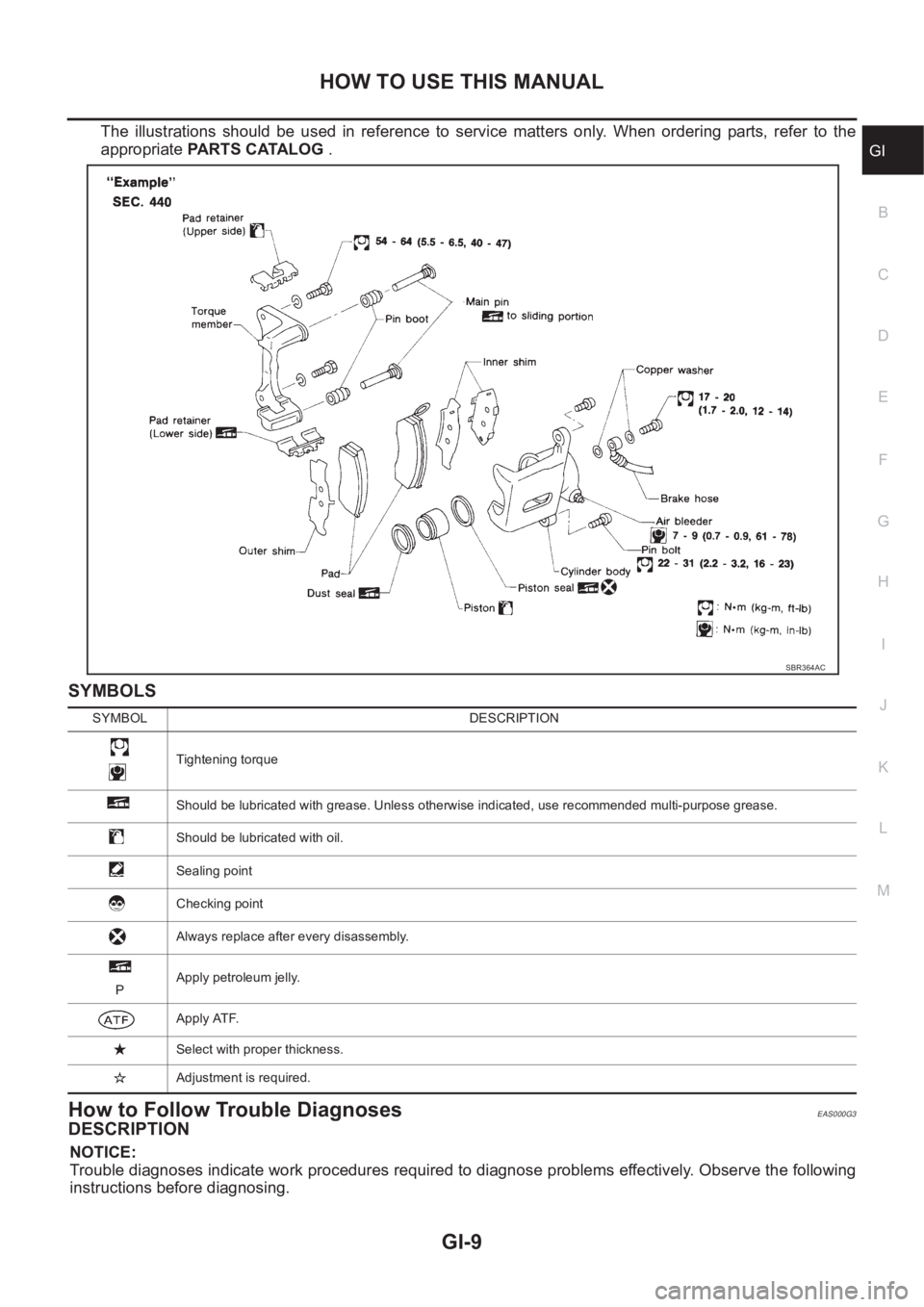
The illustrations should be used in reference to service matters only. When ordering parts, refer to the
appropriate PARTS CATALOG .
SYMBOLS
How to Follow Trouble DiagnosesEAS000G3
DESCRIPTION
NOTICE:
Trouble diagnoses indicate work procedures required to diagnose problems effectively. Observe the following
instructions before diagnosing.
SBR364AC
SYMBOL DESCRIPTION
Tightening torque
Should be lubricated with grease. Unless otherwise indicated, use recommended multi-purpose grease.
Should be lubricated with oil.
Sealing point
Checking point
Always replace after every disassembly.
PApply petroleum jelly.
Apply ATF.
Select with proper thickness.
Adjustment is required.
Page 34 of 3833

GI-32
SERVICE INFORMATION FOR ELECTRICAL INCIDENT
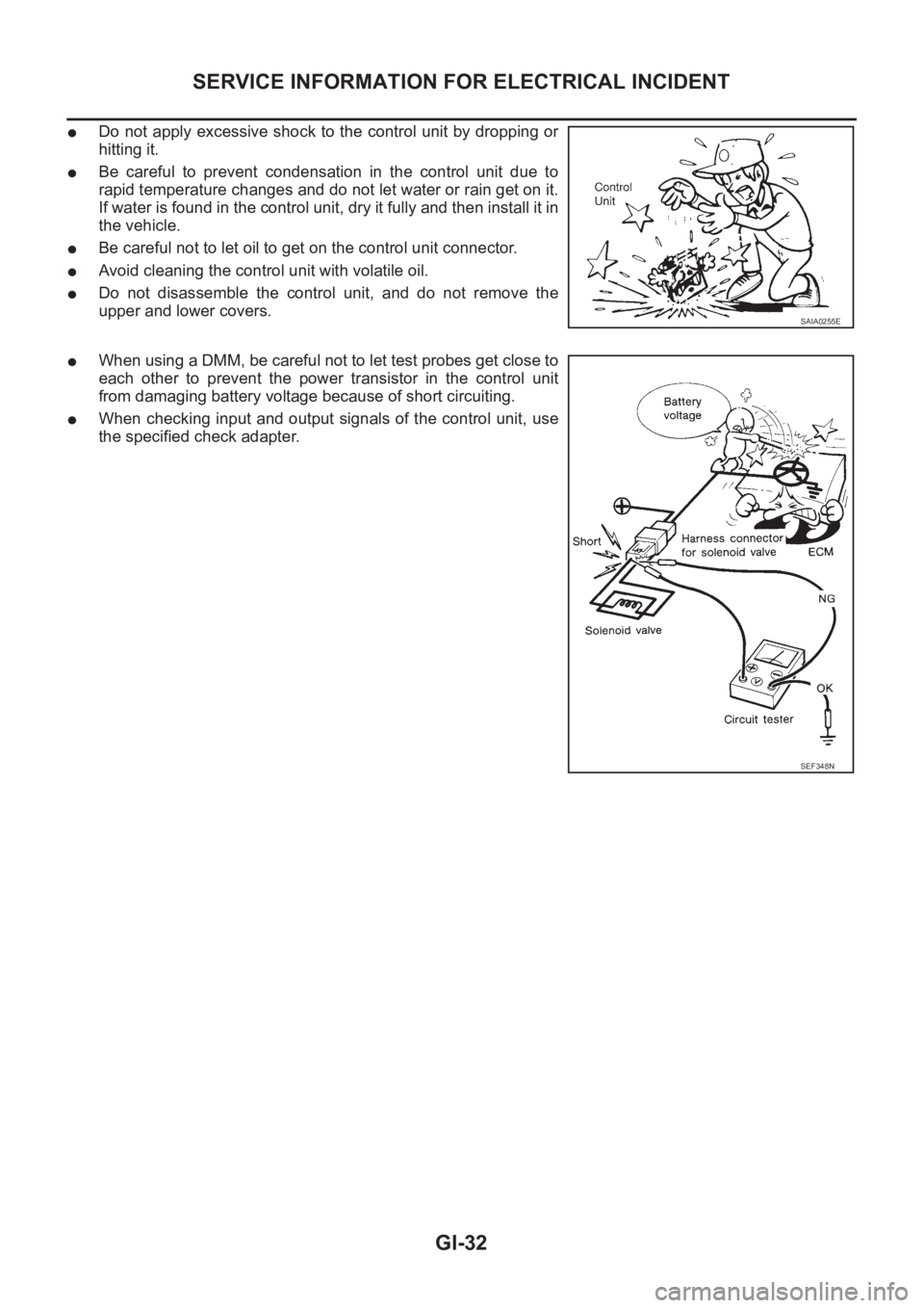
●Do not apply excessive shock to the control unit by dropping or
hitting it.
●Be careful to prevent condensation in the control unit due to
rapid temperature changes and do not let water or rain get on it.
If water is found in the control unit, dry it fully and then install it in
the vehicle.
●Be careful not to let oil to get on the control unit connector.
●Avoid cleaning the control unit with volatile oil.
●Do not disassemble the control unit, and do not remove the
upper and lower covers.
●When using a DMM, be careful not to let test probes get close to
each other to prevent the power transistor in the control unit
from damaging battery voltage because of short circuiting.
●When checking input and output signals of the control unit, use
the specified check adapter.
SAIA0255E
SEF348N
Page 51 of 3833

EM-1
ENGINE MECHANICAL
B ENGINE
CONTENTS
C
D
E
F
G
H
I
J
K
L
M
SECTION
A
EM
ENGINE MECHANICAL
QR
PRECAUTIONS .......................................................... 5
Precautions for Drain Engine Coolant ...................... 5
Precautions for Disconnecting Fuel Piping .............. 5
Precautions for Removal and Disassembly ............. 5
Precautions for Inspection, Repair and Replace-
ment ......................................................................... 5
Precautions for Assembly and Installation ............... 5
Parts Requiring Angular Tightening ......................... 5
Precautions For Liquid Gasket ................................. 6
REMOVAL OF LIQUID GASKET .......................... 6
LIQUID GASKET APPLICATION PROCEDURE ..... 6
PREPARATION ........................................................... 7
Special Service Tools ............................................... 7
Commercial Service Tools ........................................ 8
NOISE, VIBRATION, AND HARSHNESS (NVH)
TROUBLESHOOTING .............................................. 10
NVH Troubleshooting —Engine Noise ................... 10
Use the Chart Below to Help You Find the Cause
of the Symptom. ...................................................... 11
DRIVE BELTS ........................................................... 12
Checking Drive Belts .............................................. 12
Tension Adjustment ................................................ 12
Removal and Installation ........................................ 12
REMOVAL ........................................................... 12
INSTALLATION ................................................... 13
Removal and Installation of Drive Belt Auto-Ten-
sioner ..................................................................... 13
REMOVAL ........................................................... 13
INSTALLATION ................................................... 13
AIR CLEANER AND AIR DUCT ............................... 14
Removal and Installation ........................................ 14
REMOVAL ........................................................... 14
INSTALLATION ................................................... 14
CHANGING AIR CLEANER FILTER ................... 15INTAKE MANIFOLD ................................................. 16
Removal and Installation ........................................ 16
QR20DE .............................................................. 16
QR25DE .............................................................. 17
REMOVAL ........................................................... 17
INSPECTION AFTER REMOVAL ....................... 20
INSTALLATION ................................................... 20
INSPECTION AFTER INSTALLATION ................ 22
EXHAUST MANIFOLD AND THREE WAY CATA-
LYST .......................................................................... 24
Removal and Installation ........................................ 24
REMOVAL ........................................................... 24
INSPECTION AFTER REMOVAL ....................
... 25
INSTALLATION ................................................... 25
OIL PAN AND OIL STRAINER ................................. 26
Removal and Installation ........................................ 26
REMOVAL ........................................................... 26
INSPECTION AFTER REMOVAL ....................... 27
INSTALLATION ................................................... 27
INSPECTION AFTER INSTALLATION ................ 28
IGNITION COIL ......................................................... 29
Removal and Installation ........................................ 29
REMOVAL ........................................................... 29
INSTALLATION ................................................... 29
SPARK PLUG ........................................................... 30
Removal and Installation ........................................ 30
REMOVAL ........................................................... 30
INSPECTION AFTER REMOVAL ....................... 30
INSTALLATION ................................................... 31
FUEL INJECTOR AND FUEL TUBE ........................ 32
Removal and Installation ........................................ 32
QR20DE .............................................................. 32
QR25DE .............................................................. 32
REMOVAL ........................................................... 33
INSTALLATION ................................................... 33
INSPECTION AFTER INSTALLATION ................ 34
ROCKER COVER ..................................................... 35
Removal and Installation ........................................ 35
REMOVAL ........................................................... 35
INSTALLATION ................................................... 36
Page 52 of 3833

EM-2
TIMING CHAIN .......................................................... 37
Removal and Installation ........................................ 37
REMOVAL ........................................................... 38
INSPECTION AFTER REMOVAL ........................ 41
INSTALLATION .................................................... 41
CAMSHAFT ............................................................... 46
Removal and Installation ........................................ 46
REMOVAL ........................................................... 46
INSTALLATION .................................................... 48
INSPECTION AFTER REMOVAL ........................ 51
Valve Clearance ...................................................... 53
INSPECTION ....................................................... 53
ADJUSTMENT .................................................... 54
OIL SEAL .................................................................. 56
Removal and Installation of Valve Oil Seal ............. 56
REMOVAL ........................................................... 56
INSTALLATION .................................................... 56
Removal and Installation of Front Oil Seal ............. 56
REMOVAL ........................................................... 56
INSTALLATION .................................................... 57
Removal and Installation of Rear Oil Seal .............. 57
REMOVAL ........................................................... 57
INSTALLATION .................................................... 57
CYLINDER HEAD .................................................. ... 59
On-Vehicle Service ................................................. 59
CHECKING COMPRESSION PRESSURE ......... 59
Removal and Installation ........................................ 60
REMOVAL ........................................................... 60
INSPECTION AFTER REMOVAL ........................ 61
INSTALLATION .................................................... 61
Disassembly and Assembly .................................... 62
DISASSEMBLY ................................................... 63
ASSEMBLY ......................................................... 63
Inspection After Disassembly ................................. 64
CYLINDER HEAD DISTORTION ........................ 64
VALVE DIMENSIONS .......................................... 64
VALVE GUIDE CLEARANCE .............................. 65
VALVE GUIDE REPLACEMENT ......................... 65
VALVE SEAT CONTACT ..................................... 66
VALVE SEAT REPLACEMENT ........................... 66
VALVE SPRING SQUARENESS ......................... 67
VALVE SPRING DIMENSIONS AND VALVE
SPRING PRESSURE LOAD ............................... 68
ENGINE ASSEMBLY ................................................ 69
Removal and Installation ........................................ 69
REMOVAL .......................................................
.... 69
INSTALLATION .................................................... 71
INSPECTION AFTER INSTALLATION ................ 71
CYLINDER BLOCK ................................................... 73
Disassembly and Assembly .................................... 73
DISASSEMBLY ................................................... 74
ASSEMBLY ......................................................... 78
How to Select Piston and Bearing .......................... 82
DESCRIPTION .................................................... 82
HOW TO SELECT PISTON ................................. 83
HOW TO SELECT CONNECTING ROD BEAR-
ING ...................................................................... 83HOW TO SELECT MAIN BEARING .................... 85
Inspection After Disassembly .................................. 88
CRANKSHAFT END PLAY .................................. 88
CONNECTING ROD SIDE CLEARANCE ........... 89
PISTON AND PISTON PIN CLEARANCE ........... 89
PISTON RING SIDE CLEARANCE ..................... 90
PISTON RING END GAP .................................... 90
CONNECTING ROD BEND AND TORSION ....... 91
CONNECTING ROD BEARING (BIG END) ........ 91
CONNECTING ROD BUSHING OIL CLEAR-
ANCE (SMALL END) ........................................... 91
CYLINDER BLOCK DISTORTION ...................... 92
INNER DIAMETER OF MAIN BEARING HOUS-
ING ....................................................................... 93
PISTON TO CYLINDER BORE CLEARANCE .... 93
OUTER DIAMETER OF CRANKSHAFT JOUR-
NAL ...................................................................... 94
OUTER DIAMETER OF CRANKSHAFT PIN ...... 94
OUT-OF-ROUND AND TAPER OF CRANK-
SHAFT ................................................................. 94
CRANKSHAFT RUNOUT .................................... 95
CONNECTING ROD BEARING OIL CLEAR-
ANCE ................................................................... 95
MAIN BEARING OIL CLEARANCE ..................... 95
MAIN BEARING CRUSH HEIGHT ...................... 96
OUTER DIAMETER OF LOWER CYLINDER
BLOCK MOUNTING BOLT .................................. 96
OUTER DIAMETER OF CONNECTING ROD
BOLT .................................................................... 96
MOVEMENT AMOUNT OF FLYWHEEL (M/T
MODELS) ............................................................. 97
SERVICE DATA AND SPECIFICATIONS (SDS) ...... 98
Standard and Limit .................................................. 98
GENERAL SPECIFICATIONS ............................. 98
DRIVE BELTS ...................................................... 98
INTAKE MANIFOLD AND EXHAUST MANI-
FOLD ................................................................... 98
SPARK PLUG ...................................................... 98
CYLINDER HEAD ................................................ 98
VALVE .................................................................. 99
CAMSHAFT AND CAMSHAFT BEARING .........102
CYLINDER BLOCK ............................................102
PISTON, PISTON RING AND PISTON PIN .....
.103
CONNECTING ROD ..........................................104
CRANKSHAFT ...................................................105
MAIN BEARING .................................................106
CONNECTING ROD BEARING .........................107
Tightening Torque .................................................108
YD22DDTi
PRECAUTIONS .......................................................110
Precautions for Drain Engine Coolant ...................110
Precautions for Disconnecting Fuel Piping ...........110
Precautions for Removal and Disassembly ..........110
Precautions for Inspection, Repair and Replace-
ment ......................................................................110
Precautions for Assembly and Installation ............110
Page 53 of 3833

EM-3
C
D
E
F
G
H
I
J
K
L
M
EMA Parts Requiring Angular Tightening ...................... 110
Precautions For Liquid Gasket ............................. . 111
REMOVAL OF LIQUID GASKET ...................... . 111
LIQUID GASKET APPLICATION PROCEDURE . . 111
PREPARATION ........................................................112
Special Service Tools ............................................ 112
Commercial Service Tools ..................................... 115
NOISE, VIBRATION, AND HARSHNESS (NVH)
TROUBLESHOOTING .............................................116
NVH Troubleshooting —Engine Noise .................. 116
Use the Chart Below to Help You Find the Cause
of the Symptom. .................................................... 117
DRIVE BELTS ..........................................................118
Checking Drive Belts ............................................. 118
Tension Adjustment ............................................... 118
AIR CONDITIONER COMPRESSOR BELT ...... 119
ALTERNATOR AND WATER PUMP BELT ........ 119
Removal and Installation ....................................... 119
REMOVAL .......................................................... 119
INSTALLATION .................................................. 119
AIR CLEANER AND AIR DUCT ............................. 120
Removal and Installation ...................................... 120
REMOVAL ......................................................... 120
INSTALLATION ................................................. 120
CHANGING AIR CLEANER FILTER ................. 121
CHARGE AIR COOLER ......................................... 122
Removal and Installation ...................................... 122
REMOVAL ......................................................... 122
INSPECTION AFTER REMOVAL ..................... 122
INSTALLATION ................................................. 122
INTAKE MANIFOLD ............................................... 123
Removal and Installation ...................................... 123
REMOVAL ......................................................... 123
INSPECTION AFTER REMOVAL ..................... 124
INSTALLATION ................................................. 124
INSPECTION AFTER INSTALLATION ............. 125
CATALYST .............................................................. 126
Removal and Installation ...................................... 126
REMOVAL ......................................................... 126
INSTALLATION ................................................. 126
EXHAUST MANIFOLD AND TURBOCHARGER .. 127
Removal and Installation ...................................... 127
REMOVAL ......................................................... 127
INSTALLATION ................................................. 128
INSPECTION AFTER INSTALLATION ............. 128
Disassembly and Assembly ................................. 129
REMOVAL ......................................................... 129
INSPECTION AFTER REMOVAL ..................... 129
Turbocharger ........................................................ 130
ROTOR SHAFT CLEARANCE ......................... 130
ROTOR SHAFT END PLAY .............................. 130
TURBINE WHEEL ............................................. 131
COMPRESSOR WHEEL .................................. 131
WASTEGATE VALVE ACTUATOR ................... 131
TROUBLE DIAGNOSIS OF TURBOCHARGER . 132OIL PAN AND OIL STRAINER ...............................133
Removal and Installation ......................................133
REMOVAL .........................................................133
INSPECTION AFTER REMOVAL .....................135
INSTALLATION .................................................135
INSPECTION AFTER INSTALLATION ..............137
GLOW PLUG ..........................................................138
Removal and Installation ......................................138
REMOVAL .........................................................138
INSTALLATION .................................................138
VACUUM PUMP ......................................................139
Removal and Installation ......................................139
MODELS PRODUCED BEFORE MARCH 2001 .139
MODELS PRODUCED SINCE APRIL 2001 .....140
INSPECTION BEFORE REMOVAL ..................140
REMOVAL .........................................................140
INSTALLATION .................................................141
INSPECTION AFTER INSTALLATION ..............142
Disassembly and Assembly ..................................142
DISASSEMBLY .................................................142
ASSEMBLY .......................................................142
INJECTION TUBE AND FUEL INJECTOR ............144
Removal and Installation ......................................144
REMOVAL .........................................................144
INSTALLATION .................................................145
INSPECTION AFTER INSTALLATION ..............146
FUEL SUPPLY PUMP .............................................147
Removal and Installation ......................................147
REMOVAL .........................................................147
INSPECTION AFTER REMOVAL .....................152
INSTALLATION .................................................152
ROCKER COVER ...................................................156
Removal and Installation ......................................156
REMOVAL .........................................................156
INSTALLATION .................................................157
INSPECTION AFTER INSTALLATION .............
.157
CAMSHAFT ............................................................158
Removal and Installation ......................................158
REMOVAL .........................................................158
INSPECTION AFTER REMOVAL .....................159
INSTALLATION .................................................162
Valve Clearance ...................................................163
INSPECTION ....................................................163
ADJUSTMENTS ................................................164
SECONDARY TIMING CHAIN ................................167
Removal and Installation ......................................167
REMOVAL .........................................................167
INSPECTION AFTER REMOVAL .....................169
INSTALLATION .................................................170
PRIMARY TIMING CHAIN ......................................172
Removal and Installation ......................................172
REMOVAL .........................................................174
INSPECTION AFTER REMOVAL .....................177
INSTALLATION .................................................177
CYLINDER HEAD .................................................. .182
On-Vehicle Service ...............................................182
CHECKING COMPRESSION PRESSURE .......182
Removal and Installation ......................................183
REMOVAL .........................................................183
Page 83 of 3833
![NISSAN X-TRAIL 2001 Service Repair Manual FUEL INJECTOR AND FUEL TUBE
EM-33
[QR]
C
D
E
F
G
H
I
J
K
L
MA
EM
●Do not remove or disassembly parts unless instructed as shown in the figure.
REMOVAL
1. Release fuel pressure. Refer to EC-775, " NISSAN X-TRAIL 2001 Service Repair Manual FUEL INJECTOR AND FUEL TUBE
EM-33
[QR]
C
D
E
F
G
H
I
J
K
L
MA
EM
●Do not remove or disassembly parts unless instructed as shown in the figure.
REMOVAL
1. Release fuel pressure. Refer to EC-775, "](/manual-img/5/57405/w960_57405-82.png)
FUEL INJECTOR AND FUEL TUBE
EM-33
[QR]
C
D
E
F
G
H
I
J
K
L
MA
EM
●Do not remove or disassembly parts unless instructed as shown in the figure.
REMOVAL
1. Release fuel pressure. Refer to EC-775, "FUEL PRESSURE RELEASE" [QR20DE (WITH EURO-OBD)],
EC-1139, "
FUEL PRESSURE RELEASE" [QR20DE (WITHOUT EURO-OBD)], EC-42, "FUEL PRES-
SURE RELEASE" [QR25DE (WITH EURO-OBD)] or EC-452, "FUEL PRESSURE RELEASE" [QR25DE
(WITHOUT EURO-OBD)].
2. Remove air duct, air cleaner case (upper) assembly.
3. Disconnect fuel hose quick connector at fuel tube side.
●Regarding how to disconnect and connect quick connector, Refer to EM-16, "INTAKE MANIFOLD" .
CAUTION:
●Prepare a container of cloth for spilled fuel.
●This operation should be performed, in a place where free from fire.
●While hoses are disconnected seal their openings with vinyl bag or similar material to prevent
foreign material from entering them.
4. Remove intake manifold collector. Refer to EM-16, "
INTAKE MANIFOLD" .
5. Disconnect sub-harness for injector at engine front side, and remove it from bracket.
6. Loosen mounting bolts in the reverse order in the figure, and
remove fuel tube and fuel injector assembly.
7. Remove fuel tube and fuel injector assembly.
●Release clip and remove it.
●Pull fuel injector straight out of fuel tube.
●Be careful not to damage nozzle part.
●Avoid any impact such as a dropping.
●Do not disassemble or adjust it.
INSTALLATION
1. Install O-rings to fuel injector paying attention to the items below.
●Lubricate O-rings by smearing new engine oil.
●Be careful not to scratch it with a tool or fingernails dur-
ing installation. Also be careful not to twist or stretch O-
ring. If O-ring was stretched while it is attached, do no
insert it into fuel tube immediately.
2. Install fuel injector to fuel tube with the following procedure.
●Insert clip into clip mounting groove on fuel injector.
●Insert clip so that projection A of fuel injector matches notch A
of the clip.
●Do not reuse clip. Replace it with a new one.
●Be careful to keep clip from interfering with O-ring. If interfer-
ence occurs, replace O-ring.
3. Insert fuel injector into fuel tube with clip attached.
●Insert it while matching it to the axial center.
●Insert fuel injector so that projection B of fuel injector matches
notch B of the clip.
●Make sure that fuel tube flange is securely fixed in flange fixing groove on clip.
●Make sure that installation is complete by checking that fuel injector does not rotate or come off.
4. Install fuel tube assembly with the following procedure.
a. Insert the tip of each fuel injector into intake manifold.
KBIA0239E
O-ring color
Fuel tube side (Upper side) : Black
Intake manifold side (Lower side) : Green
SBIA0439E