2001 NISSAN X-TRAIL ignition
[x] Cancel search: ignitionPage 7 of 3833

PRECAUTIONS
GI-5
C
D
E
F
G
H
I
J
K
L
MB
GI
●Use approved bonding agent, sealants or their equivalents when required.
●Use tools and recommended special tools where specified for safe and efficient service repairs.
●When repairing the fuel, oil, water, vacuum or exhaust systems, check all affected lines for leaks.
●Before servicing the vehicle:
Protect fenders, upholstery and carpeting with appropriate cov-
ers.
Take caution that keys, buckles or buttons do not scratch paint.
WARNING:
To prevent ECM from storing the diagnostic trouble codes, do not carelessly disconnect the harness
connectors which are related to the engine control system and TCM (transmission control module)
system. The connectors should be disconnected only when working according to the WORK FLOW of
TROUBLE DIAGNOSES in EC and AT sections.
Precautions for All Mode 4 × 4 SystemEAS000GQ
Even if the 2WD mode is selected, the All mode 4 × 4 system occasionally changes from 2WD to 4WD auto-
matically depending on the driving conditions.
When spinning the front wheels by running the engine with the front wheels jacked up or mounted on the free
rollers / or a chassis dynamometer, be careful because the vehicle may suddenly move due to the driving
force from the rear wheels.
To avoid personal injury and vehicle damage, use one of the following methods when working with the front
wheels drive force and spinning freely.
● Remove the propeller shaft.
● Use free rollers / chassis dynamometer designed for 4WD vehicles.
Precautions for Three Way CatalystEAS000FR
If a large amount of unburned fuel flows into the catalyst, the catalyst temperature will be excessively high. To
prevent this, follow the instructions.
●Use unleaded gasoline only. Leaded gasoline will seriously damage the three way catalyst.
●When checking for ignition spark or measuring engine compression, make tests quickly and only when
necessary.
●Do not run engine when the fuel tank level is low, otherwise the engine may misfire, causing damage to
the catalyst.
Do not place the vehicle on flammable material. Keep flammable material off the exhaust pipe and the three
way catalyst.
Precautions for FuelEAS000P9
GASOLINE ENGINE
Use unleaded gasoline with an octane rating of at least 95 (RON).
CAUTION:
Do not use leaded gasoline. Using leaded gasoline will damage the three way catalyst. Using a fuel
other than that specified could adversely affect the emission control devices and systems, and could
also affect the warranty coverage validity.
DIESEL ENGINE
Diesel fuel of at least 50 cetane.
If two types of diesel fuel are available, use summer or winter fuel properly according to the following temper-
ature conditions.
●Above –7°C (20°F) ... Summer type diesel fuel.
●Below –7°C (20°F) ... Winter type diesel fuel.
SGI234
Page 8 of 3833

GI-6
PRECAUTIONS
CAUTION:
●Do not use home heating oil, gasoline or other alternate fuels in your diesel engine. The use of
those can cause engine damage.
●Do not use summer fuel at temperatures below –7°C (20°F). The cold temperatures will cause wax
to form in the fuel. As a result, it may prevent the engine from running smoothly.
●Do not add gasoline or other alternate fuels to diesel fuel.
Precautions for Multiport Fuel Injection System or Engine Control SystemEAS000FT
●Before connecting or disconnecting any harness connector for
the multiport fuel injection system or ECM:
Turn ignition switch to “OFF” position.
Disconnect negative battery terminal.
Otherwise, there may be damage to ECM.
●Before disconnecting pressurized fuel line from fuel pump to
injectors, be sure to release fuel pressure.
●Be careful not to jar components such as ECM and mass air
flow sensor.
Precautions for Turbocharger (If Equipped)EAS000FU
The turbocharger turbine revolves at extremely high speeds and
becomes very hot. Therefore, it is essential to maintain a clean sup-
ply of oil flowing through the turbocharger and to follow all required
maintenance instructions and operating procedures.
●Always use the recommended oil. Follow the instructions for
proper time to change the oil and proper oil level.
●Avoid accelerating engine to a high rpm immediately after start-
ing.
●If engine had been operating at high rpm for an extended period
of time, let it idle for a few minutes prior to shutting if off.
Precautions for HosesEAS000FV
HOSE REMOVAL AND INSTALLATION
●To prevent damage to rubber hose, do not pry off rubber hose
with tapered tool or screwdriver.
●To reinstall the rubber hose securely, make sure that hose inser-
tion length and orientation is correct. (If tube is equipped with
hose stopper, insert rubber hose into tube until it butts up
against hose stopper.)
SGI787
SGI292
SMA019D
SMA020D
Page 12 of 3833
GI-10
HOW TO USE THIS MANUAL
1.Before performing trouble diagnoses, read the “Preliminary Check”, the “Symptom Chart” or the
“Work Flow”.
2.After repairs, re-check that the problem has been completely eliminated.
3.Refer to Component Parts and Harness Connector Location for the Systems described in each
section for identification/location of components and harness connectors.
4.Refer to the Circuit Diagram for quick pinpoint check.
If you need to check circuit continuity between harness connectors in more detail, such as when a
sub-harness is used, refer to Wiring Diagram in each individual section and Harness Layout in PG
section for identification of harness connectors.
5.When checking circuit continuity, ignition switch should be OFF.
6.Before checking voltage at connectors, check battery voltage.
7.After accomplishing the Diagnostic Procedures and Electrical Components Inspection, make sure
that all harness connectors are reconnected as they were.
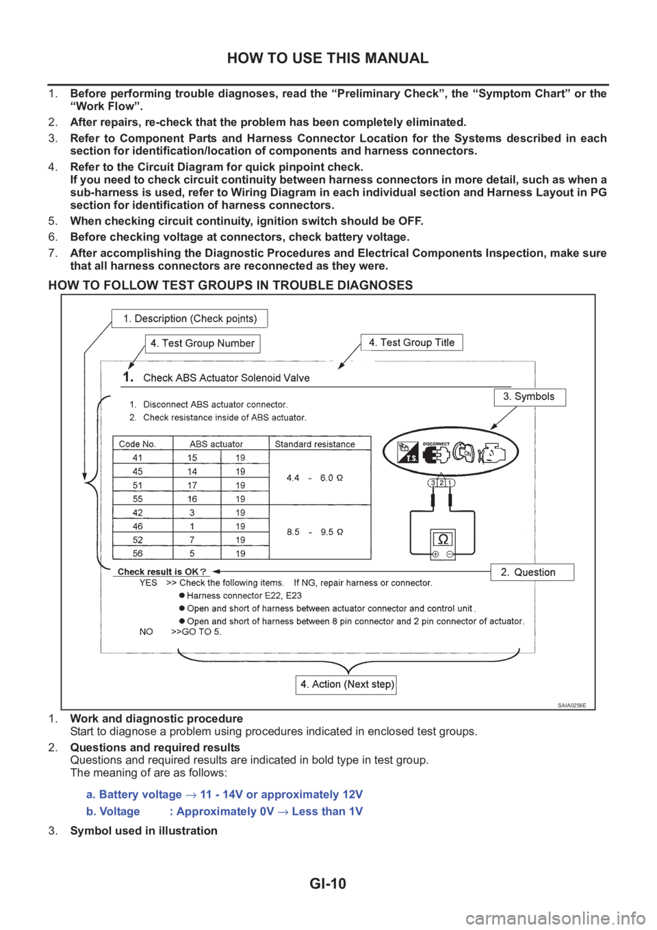
HOW TO FOLLOW TEST GROUPS IN TROUBLE DIAGNOSES
1.Work and diagnostic procedure
Start to diagnose a problem using procedures indicated in enclosed test groups.
2.Questions and required results
Questions and required results are indicated in bold type in test group.
The meaning of are as follows:
3.Symbol used in illustration
SAIA0256E
a. Battery voltage → 11 - 14V or approximately 12V
b. Voltage : Approximately 0V → Less than 1V
Page 14 of 3833
GI-12
HOW TO USE THIS MANUAL
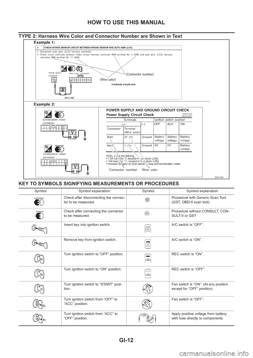
TYPE 2: Harness Wire Color and Connector Number are Shown in Text
KEY TO SYMBOLS SIGNIFYING MEASUREMENTS OR PROCEDURES
SGI144A
Symbol Symbol explanation Symbol Symbol explanation
Check after disconnecting the connec-
tor to be measured.Procedure with Generic Scan Tool
(GST, OBD-II scan tool)
Check after connecting the connector
to be measured.Procedure without CONSULT, CON-
SULT-II or GST
Insert key into ignition switch. A/C switch is “OFF”.
Remove key from ignition switch. A/C switch is “ON”.
Turn ignition switch to “OFF” position. REC switch is “ON”.
Turn ignition switch to “ON” position. REC switch is “OFF”.
Turn ignition switch to “START” posi-
tion.Fan switch is “ON”. (At any position
except for “OFF” position)
Turn ignition switch from “OFF” to
“ACC” position.Fan switch is “OFF”.
Turn ignition switch from “ACC” to
“OFF” position.Apply positive voltage from battery
with fuse directly to components.
Page 15 of 3833
HOW TO USE THIS MANUAL
GI-13
C
D
E
F
G
H
I
J
K
L
MB
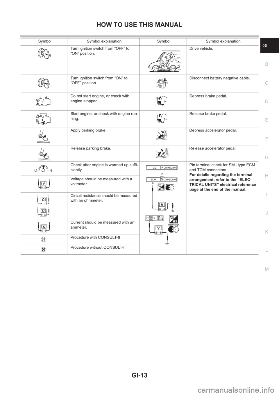
GITurn ignition switch from “OFF” to
“ON” position.Drive vehicle.
Turn ignition switch from “ON” to
“OFF” position.Disconnect battery negative cable.
Do not start engine, or check with
engine stopped.Depress brake pedal.
Start engine, or check with engine run-
ning.Release brake pedal.
Apply parking brake. Depress accelerator pedal.
Release parking brake. Release accelerator pedal.
Check after engine is warmed up suffi-
ciently.Pin terminal check for SMJ type ECM
and TCM connectors.
For details regarding the terminal
arrangement, refer to the “ELEC-
TRICAL UNITS” electrical reference
page at the end of the manual. Voltage should be measured with a
voltmeter.
Circuit resistance should be measured
with an ohmmeter.
Current should be measured with an
ammeter.
Procedure with CONSULT-II
Procedure without CONSULT-II Symbol Symbol explanation Symbol Symbol explanation
Page 20 of 3833
GI-18
HOW TO USE THIS MANUAL
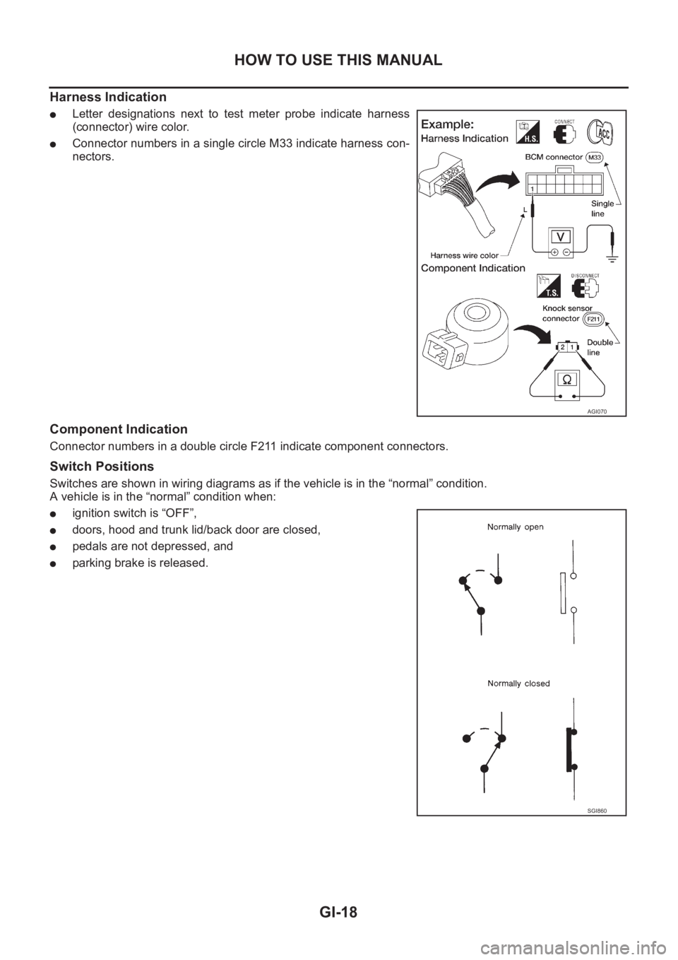
Harness Indication
●Letter designations next to test meter probe indicate harness
(connector) wire color.
●Connector numbers in a single circle M33 indicate harness con-
nectors.
Component Indication
Connector numbers in a double circle F211 indicate component connectors.
Switch Positions
Switches are shown in wiring diagrams as if the vehicle is in the “normal” condition.
A vehicle is in the “normal” condition when:
●ignition switch is “OFF”,
●doors, hood and trunk lid/back door are closed,
●pedals are not depressed, and
●parking brake is released.
AGI070
SGI860
Page 29 of 3833
SERVICE INFORMATION FOR ELECTRICAL INCIDENT
GI-27
C
D
E
F
G
H
I
J
K
L
MB
GI
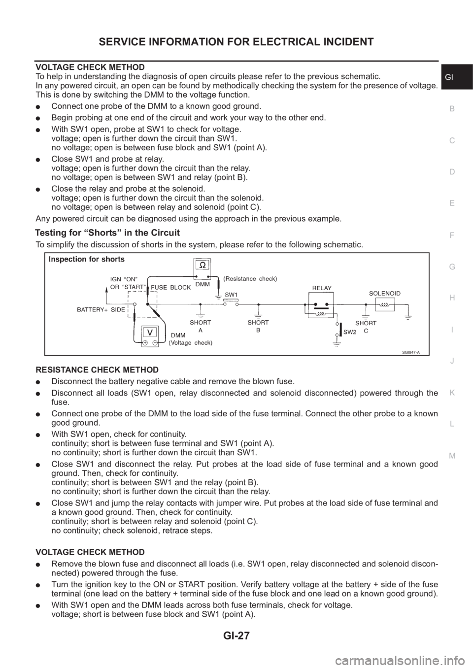
VOLTAGE CHECK METHOD
To help in understanding the diagnosis of open circuits please refer to the previous schematic.
In any powered circuit, an open can be found by methodically checking the system for the presence of voltage.
This is done by switching the DMM to the voltage function.
●Connect one probe of the DMM to a known good ground.
●Begin probing at one end of the circuit and work your way to the other end.
●With SW1 open, probe at SW1 to check for voltage.
voltage; open is further down the circuit than SW1.
no voltage; open is between fuse block and SW1 (point A).
●Close SW1 and probe at relay.
voltage; open is further down the circuit than the relay.
no voltage; open is between SW1 and relay (point B).
●Close the relay and probe at the solenoid.
voltage; open is further down the circuit than the solenoid.
no voltage; open is between relay and solenoid (point C).
Any powered circuit can be diagnosed using the approach in the previous example.
Testing for “Shorts” in the Circuit
To simplify the discussion of shorts in the system, please refer to the following schematic.
RESISTANCE CHECK METHOD
●Disconnect the battery negative cable and remove the blown fuse.
●Disconnect all loads (SW1 open, relay disconnected and solenoid disconnected) powered through the
fuse.
●Connect one probe of the DMM to the load side of the fuse terminal. Connect the other probe to a known
good ground.
●With SW1 open, check for continuity.
continuity; short is between fuse terminal and SW1 (point A).
no continuity; short is further down the circuit than SW1.
●Close SW1 and disconnect the relay. Put probes at the load side of fuse terminal and a known good
ground. Then, check for continuity.
continuity; short is between SW1 and the relay (point B).
no continuity; short is further down the circuit than the relay.
●Close SW1 and jump the relay contacts with jumper wire. Put probes at the load side of fuse terminal and
a known good ground. Then, check for continuity.
continuity; short is between relay and solenoid (point C).
no continuity; check solenoid, retrace steps.
VOLTAGE CHECK METHOD
●Remove the blown fuse and disconnect all loads (i.e. SW1 open, relay disconnected and solenoid discon-
nected) powered through the fuse.
●Turn the ignition key to the ON or START position. Verify battery voltage at the battery + side of the fuse
terminal (one lead on the battery + terminal side of the fuse block and one lead on a known good ground).
●With SW1 open and the DMM leads across both fuse terminals, check for voltage.
voltage; short is between fuse block and SW1 (point A).
SGI847-A
Page 35 of 3833
CONSULT-II CHECKING SYSTEM
GI-33
C
D
E
F
G
H
I
J
K
L
MB
GI
CONSULT-II CHECKING SYSTEMPFP:00000
DescriptionEAS000G8
●CONSULT-II is a hand-held type tester. When it is connected with a diagnostic connector equipped on the
vehicle side, it will communicate with the control unit equipped in the vehicle and then enable various
kinds of diagnostic tests.
●Refer to “CONSULT-II Software Operation Manual” for more information.
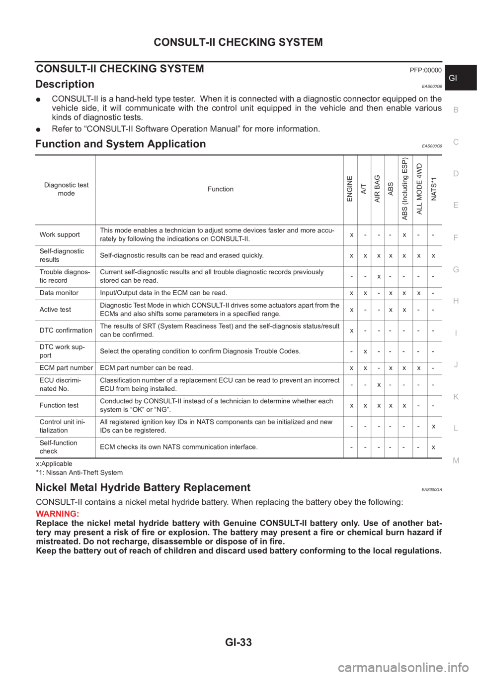
Function and System Application EAS000G9
x:Applicable
*1: Nissan Anti-Theft System
Nickel Metal Hydride Battery Replacement EAS000GA
CONSULT-II contains a nickel metal hydride battery. When replacing the battery obey the following:
WARNING:
Replace the nickel metal hydride battery with Genuine CONSULT-II battery only. Use of another bat-
tery may present a risk of fire or explosion. The battery may present a fire or chemical burn hazard if
mistreated. Do not recharge, disassemble or dispose of in fire.
Keep the battery out of reach of children and discard used battery conforming to the local regulations.
Diagnostic test
modeFunction
ENGINE
A/T
AIR BAG
ABS
ABS (Including ESP)
ALL MODE 4WD
NATS*1
Work supportThis mode enables a technician to adjust some devices faster and more accu-
rately by following the indications on CONSULT-II.x- -- x- -
Self-diagnostic
resultsSelf-diagnostic results can be read and erased quickly. x x x x x x x
Trouble diagnos-
tic recordCurrent self-diagnostic results and all trouble diagnostic records previously
stored can be read.--x----
Data monitor Input/Output data in the ECM can be read. x x - x x x -
Active testDiagnostic Test Mode in which CONSULT-II drives some actuators apart from the
ECMs and also shifts some parameters in a specified range.x- -xx- -
DTC confirmationThe results of SRT (System Readiness Test) and the self-diagnosis status/result
can be confirmed.x------
DTC work sup-
portSelect the operating condition to confirm Diagnosis Trouble Codes. -x-----
ECM part number ECM part number can be read. x x - x x x -
ECU discrimi-
nated No.Classification number of a replacement ECU can be read to prevent an incorrect
ECU from being installed.--x----
Function testConducted by CONSULT-II instead of a technician to determine whether each
system is “OK” or “NG”.xxxxx - -
Control unit ini-
tializationAll registered ignition key IDs in NATS components can be initialized and new
IDs can be registered.------x
Self-function
checkECM checks its own NATS communication interface. - - - - - - x