2001 NISSAN X-TRAIL washer fluid
[x] Cancel search: washer fluidPage 2677 of 3833
RFD-1
REAR FINAL DRIVE
D DRIVELINE/AXLE
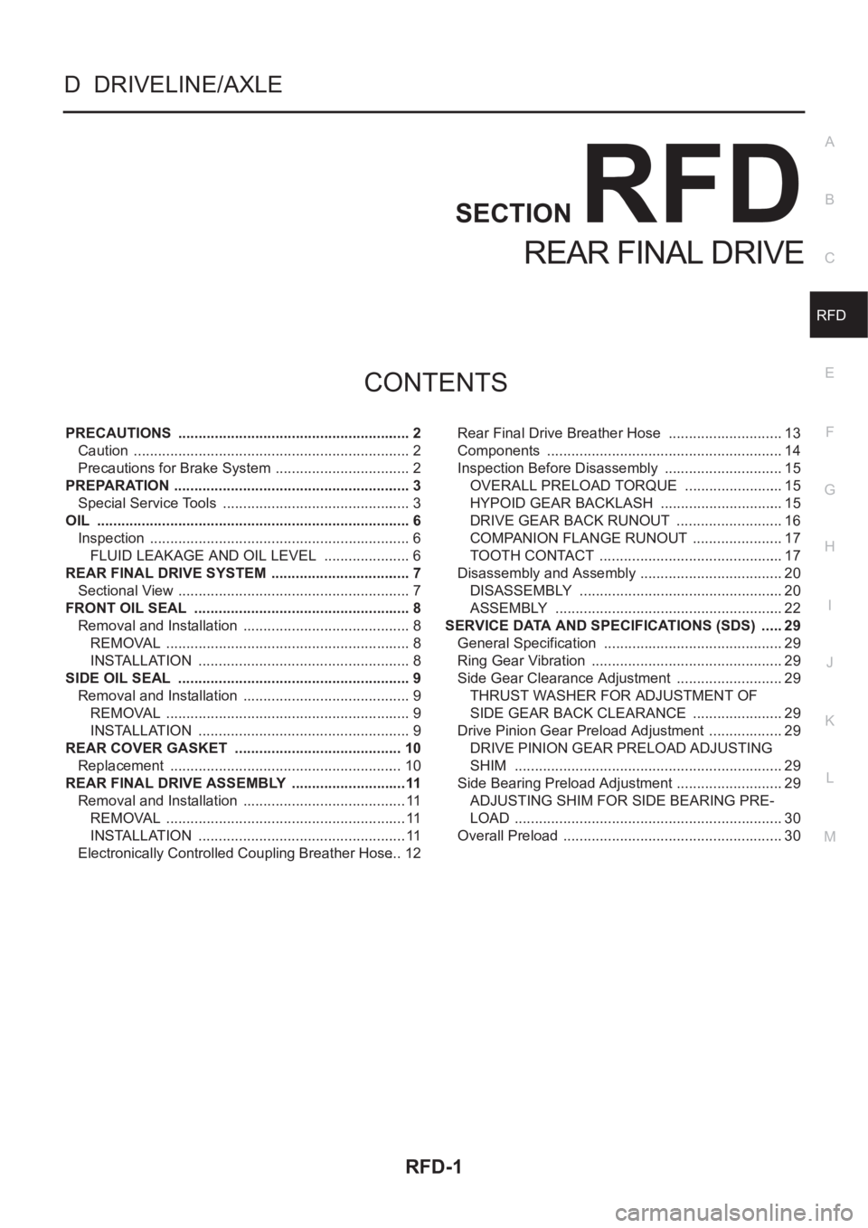
CONTENTS
C
E
F
G
H
I
J
K
L
M
SECTION
A
B
RFD
REAR FINAL DRIVE
PRECAUTIONS .......................................................... 2
Caution ..................................................................... 2
Precautions for Brake System .................................. 2
PREPARATION ........................................................... 3
Special Service Tools ............................................... 3
OIL .............................................................................. 6
Inspection ................................................................. 6
FLUID LEAKAGE AND OIL LEVEL ...................... 6
REAR FINAL DRIVE SYSTEM ................................... 7
Sectional View .......................................................... 7
FRONT OIL SEAL ................................................. ..... 8
Removal and Installation .......................................... 8
REMOVAL ............................................................. 8
INSTALLATION ..................................................... 8
SIDE OIL SEAL .......................................................... 9
Removal and Installation .......................................... 9
REMOVAL ............................................................. 9
INSTALLATION ..................................................... 9
REAR COVER GASKET .......................................... 10
Replacement .......................................................... 10
REAR FINAL DRIVE ASSEMBLY .............................11
Removal and Installation ......................................... 11
REMOVAL ............................................................ 11
INSTALLATION .................................................... 11
Electronically Controlled Coupling Breather Hose ... 12Rear Final Drive Breather Hose ............................. 13
Components ........................................................... 14
Inspection Before Disassembly .............................. 15
OVERALL PRELOAD TORQUE ......................... 15
HYPOID GEAR BACKLASH ............................... 15
DRIVE GEAR BACK RUNOUT ........................... 16
COMPANION FLANGE RUNOUT ....................... 17
TOOTH CONTACT .............................................. 17
Disassembly and Assembly .................................... 20
DISASSEMBLY ................................................... 20
ASSEMBLY ......................................................... 22
SERVICE DATA AND SPECIFICATIONS (SDS) ...... 29
General Specification ............................................. 29
Ring Gear Vibration ................................................ 29
Side Gear Clearance Adjustment ........................... 29
THRUST WASHER FOR ADJUSTMENT OF
SIDE GEAR BACK CLEARANCE ....................... 29
Drive Pinion Gear Preload Adjustment ................... 29
DRIVE PINION GEAR PRELOAD ADJUSTING
SHIM ................................................................... 29
Side Bearing Preload Adjustment ........................... 29
ADJUSTING SHIM FOR SIDE BEARING PRE-
LOAD ................................................................... 30
Overall Preload ....................................................... 30
Page 2751 of 3833
BRAKE PIPING AND HOSE
BR-11
C
D
E
G
H
I
J
K
L
MA
B
BR
BRAKE PIPING AND HOSEPFP:46210
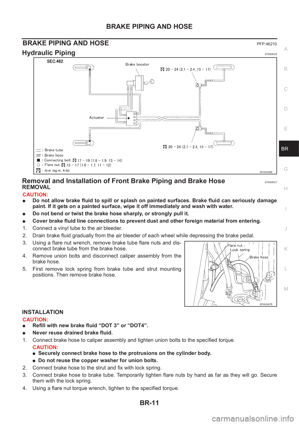
Hydraulic Piping EFS000C6
Removal and Installation of Front Brake Piping and Brake HoseEFS000C7
REMOVAL
CAUTION:
●Do not allow brake fluid to spill or splash on painted surfaces. Brake fluid can seriously damage
paint. If it gets on a painted surface, wipe it off immediately and wash with water.
●Do not bend or twist the brake hose sharply, or strongly pull it.
●Cover brake fluid line connections to prevent dust and other foreign material from entering.
1. Connect a vinyl tube to the air bleeder.
2. Drain brake fluid gradually from the air bleeder of each wheel while depressing the brake pedal.
3. Using a flare nut wrench, remove brake tube flare nuts and dis-
connect brake tube from the brake hose.
4. Remove union bolts and disconnect caliper assembly from the
brake hose.
5. First remove lock spring from brake tube and strut mounting
positions. Then remove brake hose.
INSTALLATION
CAUTION:
●Refill with new brake fluid “DOT 3” or “DOT4”.
●Never reuse drained brake fluid.
1. Connect brake hose to caliper assembly and tighten union bolts to the specified torque.
CAUTION:
●Securely connect brake hose to the protrusions on the cylinder body.
●Do not reuse the copper washer for union bolts.
2. Connect brake hose to the strut and fix with lock spring.
3. Connect brake hose to brake tube. Temporarily tighten flare nuts by hand as far as they will go. Secure
them with the lock spring.
4. Using a flare nut torque wrench, tighten to the specified torque.
SFIA0346E
SFIA0347E
Page 2763 of 3833
FRONT DISC BRAKE
BR-23
C
D
E
G
H
I
J
K
L
MA
B
BR
INSTALLATION
CAUTION:
●Refill with new brake fluid “DOT 3” or “DOT 4”.
●Never reuse drained brake fluid.
1. Install disc rotor.
2. Install caliper assembly. Tighten mounting bolts to the specified torque.
CAUTION:
Before installing caliper assembly, wipe oil and grease on steering knuckle washer seats and cali-
per assembly mounting surface.
3. Connect brake hose to caliper assembly and tighten union bolts to the specified torque.
CAUTION:
●Do not reuse the copper washer for union bolts.
●Securely assemble brake hose to protrusions on cylinder body.
4. Bleed air. Refer to BR-10, "
Bleeding Brake System" .
Caliper Disassembly and Assembly EFS000CK
DISASSEMBLY
WARNING:
Be careful not to pinch your fingers in the piston.
CAUTION:
Be careful not to damage the cylinder inner wall.
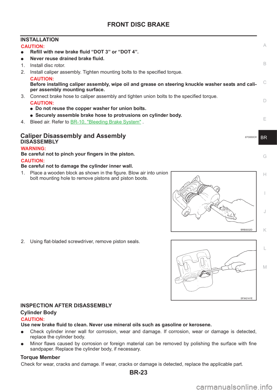
1. Place a wooden block as shown in the figure. Blow air into union
bolt mounting hole to remove pistons and piston boots.
2. Using flat-bladed screwdriver, remove piston seals.
INSPECTION AFTER DISASSEMBLY
Cylinder Body
CAUTION:
Use new brake fluid to clean. Never use mineral oils such as gasoline or kerosene.
●Check cylinder inner wall for corrosion, wear and damage. If corrosion, wear or damage is detected,
replace the cylinder body.
●Minor flaws caused by corrosion or foreign material can be removed by polishing the surface with fine
sandpaper. Replace the cylinder body, if necessary.
Torque Member
Check for wear, cracks and damage. If wear, cracks or damage is detected, replace the applicable part.
BRB0032D
SFIA0141E
Page 2766 of 3833
BR-26
REAR DISC BRAKE
REAR DISC BRAKE
PFP:44000
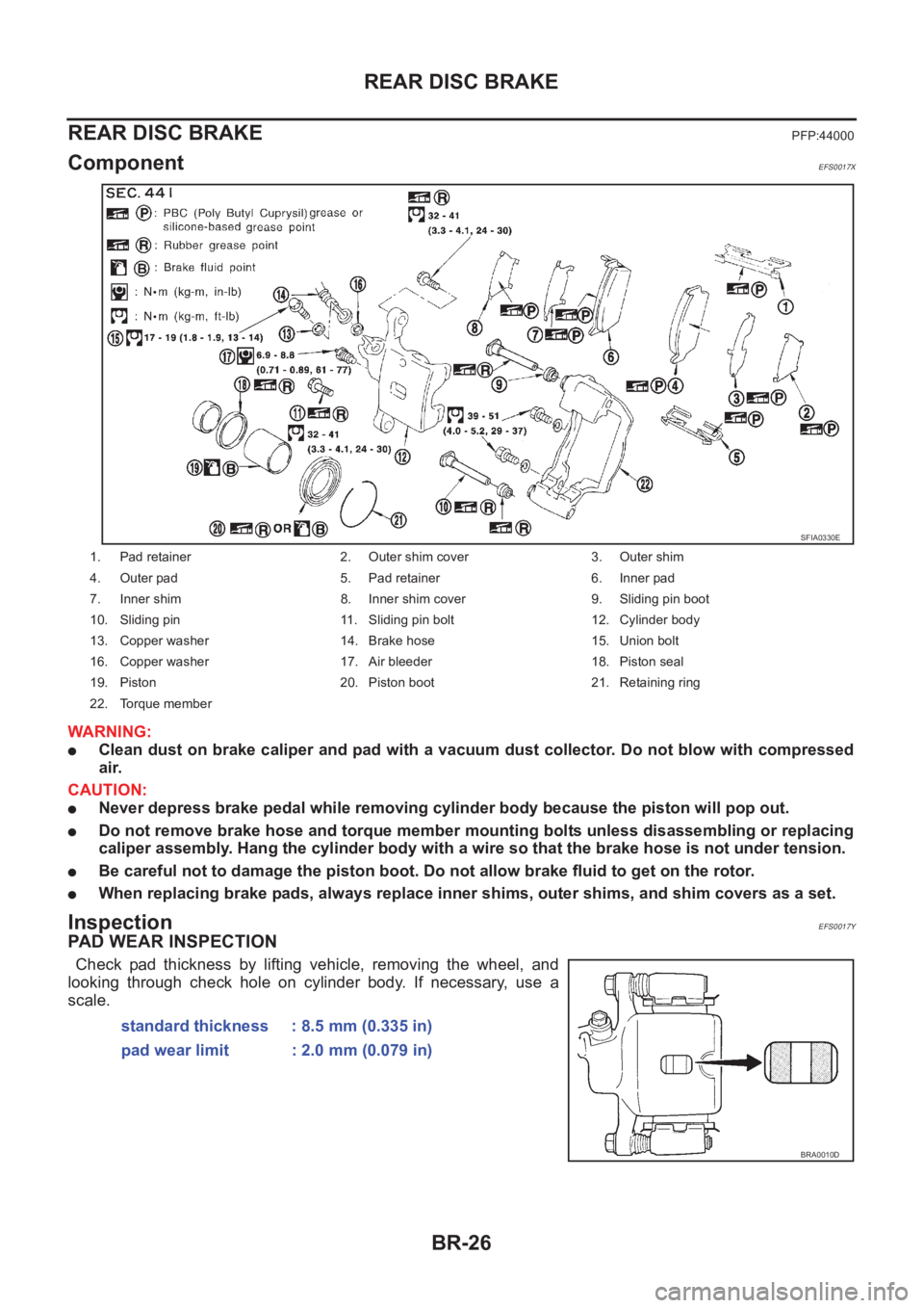
ComponentEFS0017X
WARNING:
●Clean dust on brake caliper and pad with a vacuum dust collector. Do not blow with compressed
air.
CAUTION:
●Never depress brake pedal while removing cylinder body because the piston will pop out.
●Do not remove brake hose and torque member mounting bolts unless disassembling or replacing
caliper assembly. Hang the cylinder body with a wire so that the brake hose is not under tension.
●Be careful not to damage the piston boot. Do not allow brake fluid to get on the rotor.
●When replacing brake pads, always replace inner shims, outer shims, and shim covers as a set.
InspectionEFS0017Y
PAD WEAR INSPECTION
Check pad thickness by lifting vehicle, removing the wheel, and
looking through check hole on cylinder body. If necessary, use a
scale.
1. Pad retainer 2. Outer shim cover 3. Outer shim
4. Outer pad 5. Pad retainer 6. Inner pad
7. Inner shim 8. Inner shim cover 9. Sliding pin boot
10. Sliding pin 11. Sliding pin bolt 12. Cylinder body
13. Copper washer 14. Brake hose 15. Union bolt
16. Copper washer 17. Air bleeder 18. Piston seal
19. Piston 20. Piston boot 21. Retaining ring
22. Torque member
SFIA0330E
standard thickness : 8.5 mm (0.335 in)
pad wear limit : 2.0 mm (0.079 in)
BRA0010D
Page 2768 of 3833
BR-28
REAR DISC BRAKE
Caliper Removal and Installation
EFS00180
REMOVAL
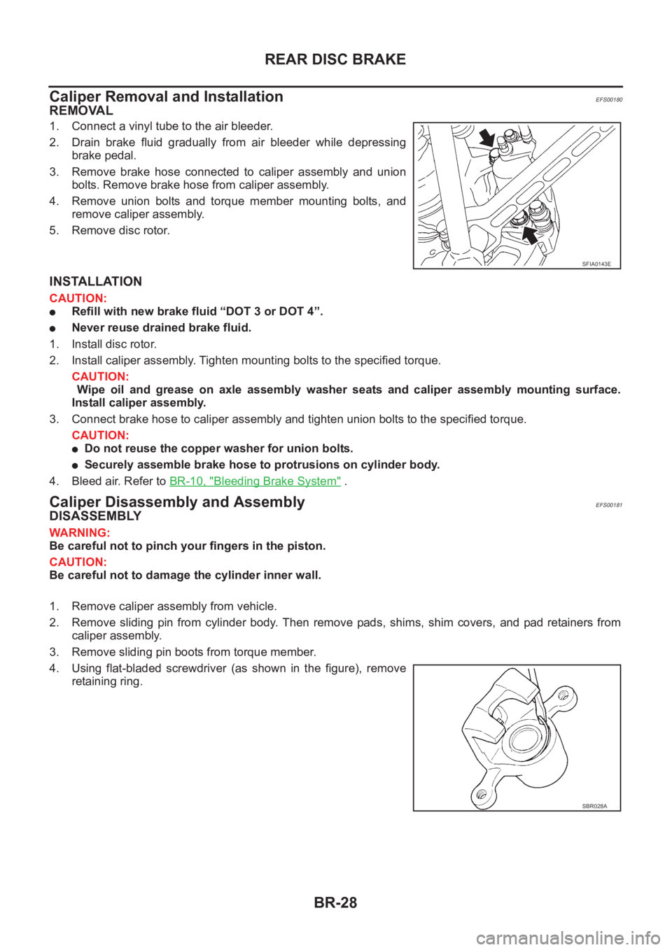
1. Connect a vinyl tube to the air bleeder.
2. Drain brake fluid gradually from air bleeder while depressing
brake pedal.
3. Remove brake hose connected to caliper assembly and union
bolts. Remove brake hose from caliper assembly.
4. Remove union bolts and torque member mounting bolts, and
remove caliper assembly.
5. Remove disc rotor.
INSTALLATION
CAUTION:
●Refill with new brake fluid “DOT 3 or DOT 4”.
●Never reuse drained brake fluid.
1. Install disc rotor.
2. Install caliper assembly. Tighten mounting bolts to the specified torque.
CAUTION:
Wipe oil and grease on axle assembly washer seats and caliper assembly mounting surface.
Install caliper assembly.
3. Connect brake hose to caliper assembly and tighten union bolts to the specified torque.
CAUTION:
●Do not reuse the copper washer for union bolts.
●Securely assemble brake hose to protrusions on cylinder body.
4. Bleed air. Refer to BR-10, "
Bleeding Brake System" .
Caliper Disassembly and AssemblyEFS00181
DISASSEMBLY
WARNING:
Be careful not to pinch your fingers in the piston.
CAUTION:
Be careful not to damage the cylinder inner wall.
1. Remove caliper assembly from vehicle.
2. Remove sliding pin from cylinder body. Then remove pads, shims, shim covers, and pad retainers from
caliper assembly.
3. Remove sliding pin boots from torque member.
4. Using flat-bladed screwdriver (as shown in the figure), remove
retaining ring.
SFIA0143E
SBR028A
Page 2771 of 3833
REAR DISC BRAKE
BR-31
C
D
E
G
H
I
J
K
L
MA
B
BR
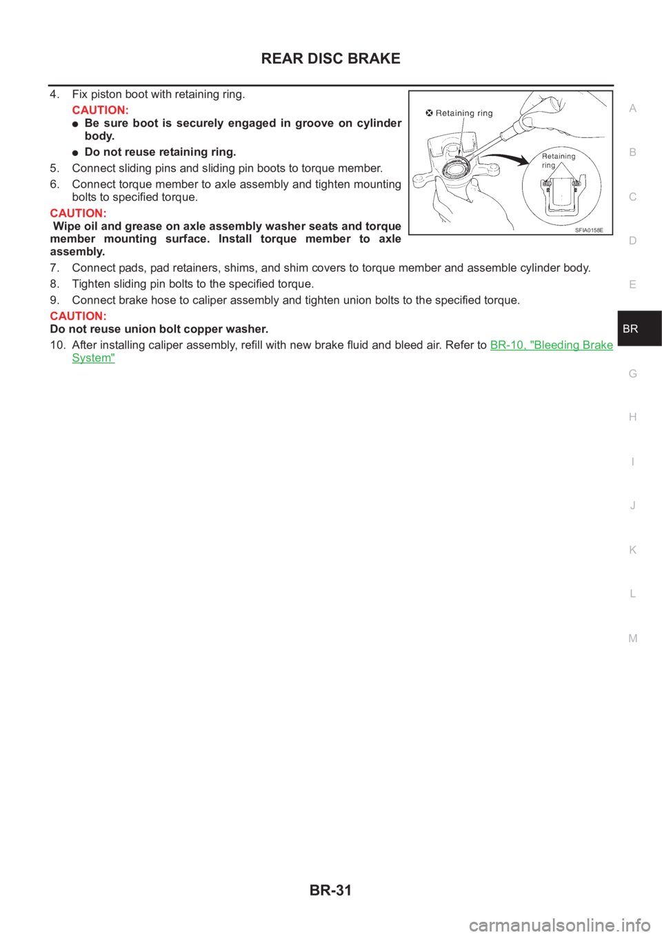
4. Fix piston boot with retaining ring.
CAUTION:
●Be sure boot is securely engaged in groove on cylinder
body.
●Do not reuse retaining ring.
5. Connect sliding pins and sliding pin boots to torque member.
6. Connect torque member to axle assembly and tighten mounting
bolts to specified torque.
CAUTION:
Wipe oil and grease on axle assembly washer seats and torque
member mounting surface. Install torque member to axle
assembly.
7. Connect pads, pad retainers, shims, and shim covers to torque member and assemble cylinder body.
8. Tighten sliding pin bolts to the specified torque.
9. Connect brake hose to caliper assembly and tighten union bolts to the specified torque.
CAUTION:
Do not reuse union bolt copper washer.
10. After installing caliper assembly, refill with new brake fluid and bleed air. Refer to BR-10, "
Bleeding Brake
System"
SFIA0158E
Page 2912 of 3833
PS-2
PRECAUTIONS
PRECAUTIONS
PFP:00001
Precautions for Supplemental Restraint System (SRS) “AIR BAG” and “SEAT
BELT PRE-TENSIONER”
EGS000IZ
The Supplemental Restraint System such as “AIR BAG” and “SEAT BELT PRE-TENSIONER”, used along
with a front seat belt, helps to reduce the risk or severity of injury to the driver and front passenger for certain
types of collision. Information necessary to service the system safely is included in the SRS and SB section of
this Service Manual.
WARNING:
●To avoid rendering the SRS inoperative, which could increase the risk of personal injury or death
in the event of a collision which would result in air bag inflation, all maintenance must be per-
formed by an authorized NISSAN/INFINITI dealer.
●Improper maintenance, including incorrect removal and installation of the SRS, can lead to per-
sonal injury caused by unintentional activation of the system. For removal of Spiral Cable and Air
Bag Module, see the SRS section.
●Do not use electrical test equipment on any circuit related to the SRS unless instructed to in this
Service Manual. SRS wiring harnesses can be identified by yellow and/or orange harness connec-
tors.
CautionEGS00049
●Always follow the warnings and the cautions below in disassembly procedures:
–Work in a clean, dust-free place. No dust proof device is necessary.
–Clean outside of unit before disassembly.
–Clean parts to be disassembled. Be careful not to allow any dirt or other foreign materials to enter or con-
tact with parts.
–Assemble disassembled parts properly, following order shown in manual. If work has been suspended in
the middle of assembly, place a clean cover over parts. This will prevent them from being contaminated.
–Use paper towels when removing dirt and other foreign materials. Cloth shop towels can leave lint on
cleaned parts that might affect operation of parts.
–Clean disassembled parts (except rubber parts) with kerosene. Drain oil by blowing with air or absorbing
with shop papers.
–Before assembling, apply Nissan power steering fluid to O-rings and seals.
–Replace gaskets and O-rings with new ones. Be careful not to damage any O-rings, oil seals, and gaskets
during assembly.
●If following part is scratched after disassembly of steering pump, replace applicable part: case, rear body,
side plate, pulley, rotor, vane, or flow control valve
●Mark source of fluid leak with a white marker for identification.
● Seals and copper washers must not be reused.
Page 2915 of 3833
POWER STEERING FLUID
PS-5
C
D
E
F
H
I
J
K
L
MA
B
PS
POWER STEERING FLUIDPFP:KLF20
Checking Fluid LevelEGS0004B
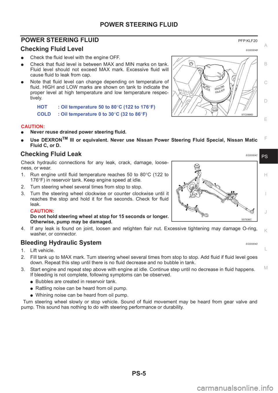
●Check the fluid level with the engine OFF.
●Check that fluid level is between MAX and MIN marks on tank.
Fluid level should not exceed MAX mark. Excessive fluid will
cause fluid to leak from cap.
●Note that fluid level can change depending on temperature of
fluid. HIGH and LOW marks are shown on tank to indicate the
proper level at high temperature and low temperature respec-
tively.
CAUTION:
●Never reuse drained power steering fluid.
●Use DEXRONTM III or equivalent. Never use Nissan Power Steering Fluid Special, Nissan Matic
Fluid C, or D.
Checking Fluid LeakEGS0004C
Check hydraulic connections for any leak, crack, damage, loose-
ness, or wear.
1. Run engine until fluid temperature reaches 50 to 80°C (122 to
176°F) in reservoir tank. Keep engine speed at idle.
2. Turn steering wheel several times from stop to stop.
3. Turn the steering wheel clockwise or counter clockwise until it
reaches the stop and hold it for five seconds. Check for fluid
leak.
CAUTION:
Do not hold steering wheel at stop for 15 seconds or longer.
Otherwise, pump may be damaged.
4. If any leak is found on joint, loosen and retighten flair nut. Excessive tightening may damage O-ring,
washer, or connector.
Bleeding Hydraulic SystemEGS0004D
1. Lift vehicle.
2. Fill tank up to MAX mark. Turn steering wheel several times from stop to stop. Add fluid if fluid level goes
down. Repeat this step until there is no fluid decrease and no bubble in tank.
3. Start engine and repeat step above with engine at idle. Continue step until no decrease in fluid happens.
If bleeding is not complete, following symptoms can be observed.
●Bubbles are created in reservoir tank.
●Rattling noise can be heard from oil pump.
●Whining noise can be heard from oil pump.
Turn steering wheel slowly or stop vehicle. Sound of fluid movement may be heard from gear valve and
pump. This sound has nothing to do with steering performance or durability. HOT : Oil temperature 50 to 80°C (122 to 176°F)
COLD : Oil temperature 0 to 30°C (32 to 86°F)
STC0996D
SST836C