2001 NISSAN X-TRAIL washer fluid
[x] Cancel search: washer fluidPage 3423 of 3833
REFRIGERANT LINES
ATC-147
C
D
E
F
G
H
I
K
L
MA
B
AT C
Checking System for Leaks Using the Fluorescent Leak DetectorEJS000VK
1. Check A/C system for leaks using the UV lamp and safety goggles (J-42220) in a low sunlight area (area
without windows preferable). Illuminate all components, fittings and lines. The dye will appear as a bright
green/yellow area at the point of leakage. Fluorescent dye observed at the evaporator drain opening indi-
cates an evaporator core assembly (tubes, core or expansion valve) leak.
2. If the suspected area is difficult to see, use an adjustable mirror or wipe the area with a clean shop rag or
cloth, with the UV lamp for dye residue.
3. After the leak is repaired, remove any residual dye using dye cleaner (J-43872) to prevent future misdiag-
nosis.
4. Perform a system performance check and verify the leak repair with an approved electronic refrigerant
leak detector.
NOTE:
Other gases in the work area or substances on the A/C components, for example, anti-freeze, windshield
washer fluid, solvents and lubricants, may falsely trigger the leak detector. Make sure the surfaces to be
checked are clean.
Clean with a dry cloth or blow off with shop air.
Do not allow the sensor tip of the detector to contact with any substance. This can also cause false readings
and may damage the detector.
Dye InjectionEJS000VL
(This procedure is only necessary when recharging the system or when the compressor has seized and was
replaced.)
1. Check A/C system static (at rest) pressure. Pressure must be at least 345 kPa (50 psi).
2. Pour one bottle (1/4 ounce / 7.4 cc) of the A/C refrigerant dye into the injector tool (J-41459).
3. Connect the injector tool to the A/C LOW PRESSURE side service fitting.
4. Start engine and switch A/C ON.
5. When the A/C operating (compressor running), inject one bottle (1/4 ounce / 7.4 cc) of fluorescent dye
through the low-pressure service valve using dye injector tool J-41459 (refer to the manufacture's operat-
ing instructions).
6. With the engine still running, disconnect the injector tool from the service fitting.
CAUTION:
Be careful the A/C system or replacing a component, pour the dye directly into the open system con-
nection and proceed with the service procedures.
7. Operate the A/C system for a minimum of 20 minutes to mix the dye with the system oil. Depending on the
leak size, operating conditions and location of the leak, it may take from minutes to days for the dye to
penetrate a leak and become visible.
Electronic Refrigerant Leak DetectorEJS000VM
PRECAUTIONS FOR HANDLING LEAK DETECTOR
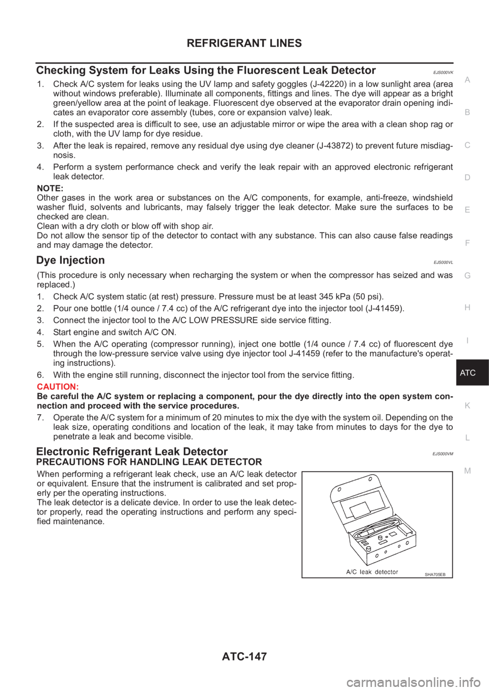
When performing a refrigerant leak check, use an A/C leak detector
or equivalent. Ensure that the instrument is calibrated and set prop-
erly per the operating instructions.
The leak detector is a delicate device. In order to use the leak detec-
tor properly, read the operating instructions and perform any speci-
fied maintenance.
SHA705EB
Page 3635 of 3833
FRONT WIPER AND WASHER SYSTEM
WW-7
C
D
E
F
G
H
I
J
L
MA
B
WW
Terminal and Reference Values for Combination SwitchEKS0032P
Removal and Installation for Front Wiper Arms, Adjustment for Wiper Arms
Stop Location
EKS0032Q
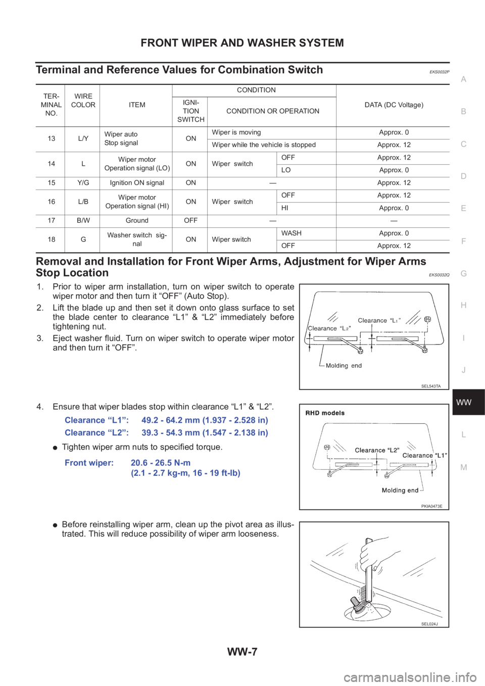
1. Prior to wiper arm installation, turn on wiper switch to operate
wiper motor and then turn it “OFF” (Auto Stop).
2. Lift the blade up and then set it down onto glass surface to set
the blade center to clearance “L1” & “L2” immediately before
tightening nut.
3. Eject washer fluid. Turn on wiper switch to operate wiper motor
and then turn it “OFF”.
4. Ensure that wiper blades stop within clearance “L1” & “L2”.
●Tighten wiper arm nuts to specified torque.
●Before reinstalling wiper arm, clean up the pivot area as illus-
trated. This will reduce possibility of wiper arm looseness.
TER-
MINAL
NO.WIRE
COLOR ITEM CONDITION
DATA (DC Voltage) IGNI-
TION
SWITCHCONDITION OR OPERATION
13 L/YWiper auto
Stop signalONWiper is moving Approx. 0
Wiper while the vehicle is stopped Approx. 12
14 LWiper motor
Operation signal (LO)ON Wiper switchOFF Approx. 12
LO Approx. 0
15 Y/G Ignition ON signal ON — Approx. 12
16 L/BWiper motor
Operation signal (HI)ON Wiper switchOFF Approx. 12
HI Approx. 0
17 B/W Ground OFF — —
18 GWasher switch sig-
nalON Wiper switchWASH Approx. 0
OFF Approx. 12
SEL543TA
Clearance “L1”: 49.2 - 64.2 mm (1.937 - 2.528 in)
Clearance “L2”: 39.3 - 54.3 mm (1.547 - 2.138 in)
Front wiper: 20.6 - 26.5 N-m
(2.1 - 2.7 kg-m, 16 - 19 ft-lb)
PKIA0473E
SEL024J
Page 3643 of 3833
REAR WIPER AND WASHER SYSTEM
WW-15
C
D
E
F
G
H
I
J
L
MA
B
WW
Terminal and Reference Values for Combination SwitchEKS00330
Removal and Installation for Rear Wiper Arms EKS00331
WIPER ARMS
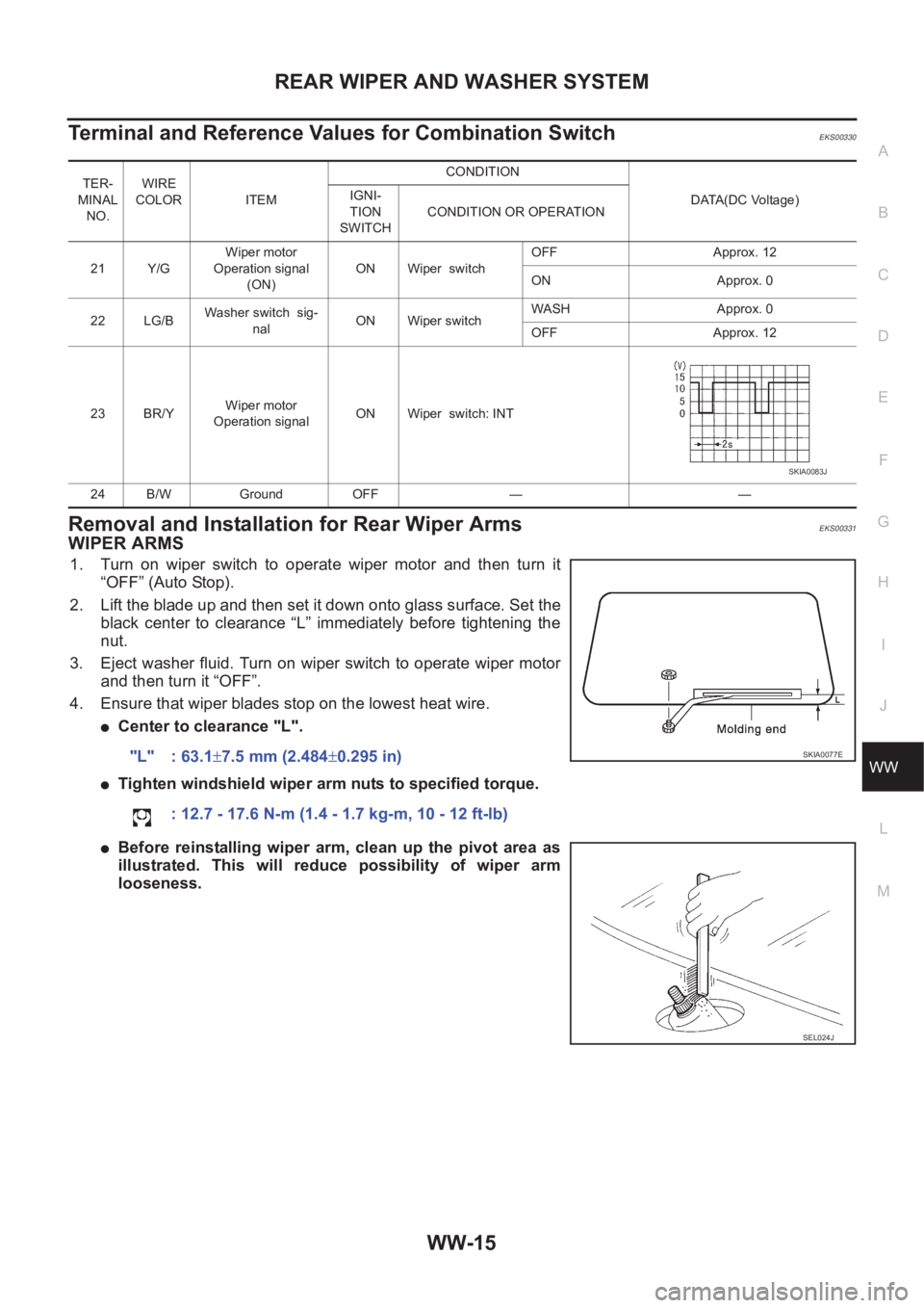
1. Turn on wiper switch to operate wiper motor and then turn it
“OFF” (Auto Stop).
2. Lift the blade up and then set it down onto glass surface. Set the
black center to clearance “L” immediately before tightening the
nut.
3. Eject washer fluid. Turn on wiper switch to operate wiper motor
and then turn it “OFF”.
4. Ensure that wiper blades stop on the lowest heat wire.
●Center to clearance "L".
●Tighten windshield wiper arm nuts to specified torque.
●Before reinstalling wiper arm, clean up the pivot area as
illustrated. This will reduce possibility of wiper arm
looseness.
TER-
MINAL
NO.WIRE
COLOR ITEM CONDITION
DATA(DC Voltage) IGNI-
TION
SWITCHCONDITION OR OPERATION
21 Y/GWiper motor
Operation signal
(ON)ON Wiper switchOFF Approx. 12
ON Approx. 0
22 LG/BWasher switch sig-
nalON Wiper switchWASH Approx. 0
OFF Approx. 12
23 BR/YWiper motor
Operation signalON Wiper switch: INT
24 B/W Ground OFF — —
SKIA0083J
"L" : 63.1±7.5 mm (2.484±0.295 in)
: 12.7 - 17.6 N-m (1.4 - 1.7 kg-m, 10 - 12 ft-lb)SKIA0077E
SEL024J
Page 3784 of 3833
MA-4
DESCRIPTION
DESCRIPTION
PFP:00000
Pre-delivery Inspection ItemsELS000AK
Shown below are Pre-delivery Inspection Items required for the new vehicle. It is recommended that
necessary items other than those listed here be added, paying due regard to the conditions in each
country.
Perform applicable items on each model. Consult text of this section for specifications.
UNDER HOOD — engine off
Radiator coolant level and coolant hose connections for leaks
Battery fluid level, specific gravity and conditions of battery terminals
Drive belts tension
Fuel filter for water or dusts (Diesel only), and fuel lines and connections for leaks
Engine oil level and oil leaks
Clutch and brake reservoir fluid level and fluid lines for leaks
Windshield and rear window washer and headlamp cleaner reservoir fluid level
Power steering reservoir fluid level and hose connections for leaks
ON INSIDE AND OUTSIDE
Remove front spring/strut spacer (If applicable)
Operation of all instruments, gauges, lights and accessories
Operation of horn(s), wiper and washer
Steering lock for operation
Check air conditioner for gas leaks
Front and rear seats, and seat belts for operation
All moldings, trims and fittings for fit and alignment
All windows for operation and alignment
Hood, trunk lid, door panels for fit and alignment
Latches, keys and locks for operation
Weatherstrips for adhesion and fit
Headlamp aiming
Tighten wheel nuts (Inc. inner nuts if applicable)
Tire pressure (Inc. spare tire)
Check front wheels for toe-in
Install clock/voltmeter/room lamp fuse (If applicable)
Install deodorizing filter to air conditioner (If applicable)
Remove wiper blade protectors (If applicable)
UNDER BODY
Manual transmission/transaxle, transfer and differential gear oil level
Brake and fuel lines and oil/fluid reservoirs for leaks
Tighten bolts and nuts of steering linkage and gear box, suspension, propeller shafts and drive shafts
Tighten rear body bolts and nuts (Models with wooden bed only)
ROAD TEST
Clutch operation
Parking brake operation
Service brake operation
Automatic transmission/transaxle shift timing and kickdown
Steering control and returnability
Engine performance
Page 3786 of 3833

MA-6
GENERAL MAINTENANCE
GENERAL MAINTENANCE
PFP:00000
General MaintenanceELS000AL
General maintenance includes those items which should be checked during the normal day-to-day operation
of the vehicle. They are essential if the vehicle is to continue operating properly. The owners can perform the
checks and inspections themselves or they can have their NISSAN dealers do them for a nominal charge.
OUTSIDE THE VEHICLE
The maintenance items listed here should be performed from time to time, unless otherwise specified.
INSIDE THE VEHICLE
The maintenance items listed here should be checked on a regular basis, such as when performing periodic maintenance, cleaning the
vehicle, etc.
UNDER THE HOOD AND VEHICLE
The maintenance items listed here should be checked periodically e.g. each time you check the engine oil or refuel. Item Reference page
TiresCheck the pressure with a gauge periodically when at a service station, includ-
ing the spare, and adjust to the specified pressure if necessary. Check carefully
for damage, cuts or excessive wear.—
Windshield wiper
bladesCheck for cracks or wear if not functioning correctly. —
Doors and engine
hoodCheck that all doors, the engine hood, the trunk lid and back door operate prop-
erly. Also ensure that all latches lock securely. Lubricate if necessary. Make sure
that the secondary latch keeps the hood from opening when the primary latch is
released.
When driving in areas using road salt or other corrosive materials, check for
lubrication frequently.BL-4
,BL-8
Tire rotationTires should be rotated every 5,000 km (3,000 miles).MA-38
Item Reference page
LampsMake sure that the headlamps, stop lamps, tail lamps, turn signal lamps, and
other lamps are all operating properly and installed securely. Also check head-
lamp aim.—
Warning lamps and
chimesMake sure that all warning lamps and buzzers/chimes are operating properly. —
Steering wheelCheck that it has the specified play.
Check for changes in the steering conditions, such as excessive free play, hard
steering or strange noises.
Free play: Less than 35 mm (1.38 in)—
Seat beltsCheck that all parts of the seat belt system (e.g. buckles, anchors, a dju sters and
retractors) operate properly and smoothly, and are installed securely. Check the
belt webbing for cuts, fraying, wear or damage.SB-3
Item Reference page
Windshield washer
fluidCheck that there is adequate fluid in the tank. —
Engine coolant levelCheck the coolant level when the engine is cold.CO-29
(QR20DE,
QR25DE)
CO-29
(YD22DDTi)
Engine oil levelCheck the level after parking the vehicle (on level ground) and turning off the
engine.LU-18
(QR20DE,
QR25DE)
LU-18
(YD22DDTi)
Brake and clutch fluid
levelsMake sure that the brake and clutch fluid levels are between the “MAX” and
“MIN” lines on the reservoir.MA-35
,MA-39
BatteryCheck the fluid level in each cell. It should be between the “MAX” and “MIN”
lines.—
Page 3803 of 3833
ENGINE MAINTENANCE (QR20DE·QR25DE)
MA-23
C
D
E
F
G
H
I
J
K
MA
B
MA
Changing Engine OilELS000JZ
WARNING:
●Be careful not to burn yourself, as the engine oil is hot.
●Prolonged and repeated contact with used engine oil may
cause skin cancer. Try to avoid direct skin contact with
used engine oil. If skin contact is made, wash thoroughly
with soap or hand cleaner as soon as possible.
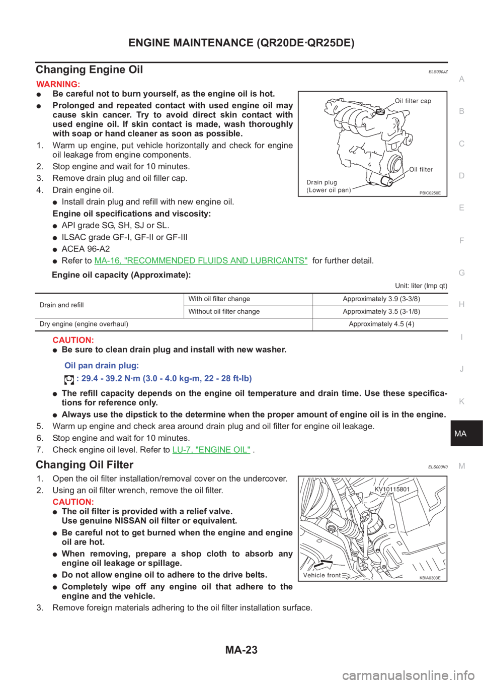
1. Warm up engine, put vehicle horizontally and check for engine
oil leakage from engine components.
2. Stop engine and wait for 10 minutes.
3. Remove drain plug and oil filler cap.
4. Drain engine oil.
●Install drain plug and refill with new engine oil.
Engine oil specifications and viscosity:
●API grade SG, SH, SJ or SL.
●ILSAC grade GF-I, GF-II or GF-III
●ACEA 96-A2
●Refer to MA-16, "RECOMMENDED FLUIDS AND LUBRICANTS" for further detail.
Engine oil capacity (Approximate):
Unit: liter (lmp qt)
CAUTION:
●Be sure to clean drain plug and install with new washer.
●The refill capacity depends on the engine oil temperature and drain time. Use these specifica-
tions for reference only.
●Always use the dipstick to the determine when the proper amount of engine oil is in the engine.
5. Warm up engine and check area around drain plug and oil filter for engine oil leakage.
6. Stop engine and wait for 10 minutes.
7. Check engine oil level. Refer to LU-7, "
ENGINE OIL" .
Changing Oil FilterELS000K0
1. Open the oil filter installation/removal cover on the undercover.
2. Using an oil filter wrench, remove the oil filter.
CAUTION:
●The oil filter is provided with a relief valve.
Use genuine NISSAN oil filter or equivalent.
●Be careful not to get burned when the engine and engine
oil are hot.
●When removing, prepare a shop cloth to absorb any
engine oil leakage or spillage.
●Do not allow engine oil to adhere to the drive belts.
●Completely wipe off any engine oil that adhere to the
engine and the vehicle.
3. Remove foreign materials adhering to the oil filter installation surface.
PBIC0250E
Drain and refillWith oil filter change Approximately 3.9 (3-3/8)
Without oil filter change Approximately 3.5 (3-1/8)
Dry engine (engine overhaul)Approximately 4.5 (4)
Oil pan drain plug:
: 29.4 - 39.2 N·m (3.0 - 4.0 kg-m, 22 - 28 ft-lb)
KBIA0303E
Page 3808 of 3833
MA-28
ENGINE MAINTENANCE (YD22DDTI)
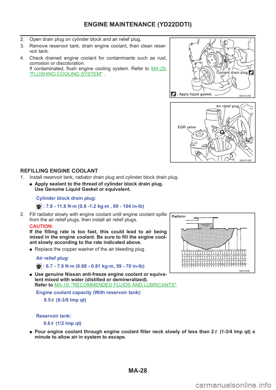
2. Open drain plug on cylinder block and air relief plug.
3. Remove reservoir tank, drain engine coolant, then clean reser-
voir tank.
4. Check drained engine coolant for contaminants such as rust,
corrosion or discoloration.
If contaminated, flush engine cooling system. Refer to MA-29,
"FLUSHING COOLING SYSTEM" .
REFILLING ENGINE COOLANT
1. Install reservoir tank, radiator drain plug and cylinder block drain plug.
●Apply sealant to the thread of cylinder block drain plug.
Use Genuine Liquid Gasket or equivalent.
2. Fill radiator slowly with engine coolant until engine coolant spills
from the air relief plugs, then install air relief plugs.
CAUTION:
If the filling rate is too fast, this could lead to air being
mixed in the engine coolant. Be sure to fill the engine cool-
ant slowly according to the rate indicated above.
●Replace the copper washer of the air bleeding plug.
●Use genuine Nissan anti-freeze engine coolant or equiva-
lent mixed with water (distilled or demineralized).
Refer to MA-16, "
RECOMMENDED FLUIDS AND LUBRICANTS".
●Pour engine coolant through engine coolant filler neck slowly of less than 2 (1-3/4 lmp qt) a
minute to allow air in system to escape.
SBIA0129E
SBIA0130E
Cylinder block drain plug:
: 7.8 - 11.8 N·m (0.8 -1.2 kg-m , 69 - 104 in-lb)
Air relief plug:
: 6.7 - 7.9 N·m (0.68 - 0.81 kg-m, 59 - 70 in-lb)
Engine coolant capacity (With reservoir tank):
9.5 (8-3/8 Imp qt)
SMA182B
Reservoir tank:
0.6 (1/2 lmp qt)
Page 3812 of 3833
MA-32
ENGINE MAINTENANCE (YD22DDTI)
Changing Air Cleaner Filter
ELS000CG
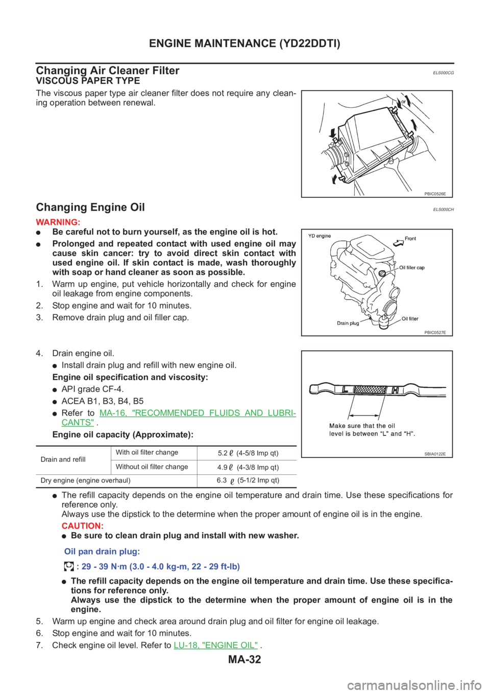
VISCOUS PAPER TYPE
The viscous paper type air cleaner filter does not require any clean-
ing operation between renewal.
Changing Engine OilELS000CH
WARNING:
●Be careful not to burn yourself, as the engine oil is hot.
●Prolonged and repeated contact with used engine oil may
cause skin cancer: try to avoid direct skin contact with
used engine oil. If skin contact is made, wash thoroughly
with soap or hand cleaner as soon as possible.
1. Warm up engine, put vehicle horizontally and check for engine
oil leakage from engine components.
2. Stop engine and wait for 10 minutes.
3. Remove drain plug and oil filler cap.
4. Drain engine oil.
●Install drain plug and refill with new engine oil.
Engine oil specification and viscosity:
●API grade CF-4.
●ACEA B1, B3, B4, B5
●Refer to MA-16, "RECOMMENDED FLUIDS AND LUBRI-
CANTS" .
Engine oil capacity (Approximate):
●The refill capacity depends on the engine oil temperature and drain time. Use these specifications for
reference only.
Always use the dipstick to the determine when the proper amount of engine oil is in the engine.
CAUTION:
●Be sure to clean drain plug and install with new washer.
●The refill capacity depends on the engine oil temperature and drain time. Use these specifica-
tions for reference only.
Always use the dipstick to the determine when the proper amount of engine oil is in the
engine.
5. Warm up engine and check area around drain plug and oil filter for engine oil leakage.
6. Stop engine and wait for 10 minutes.
7. Check engine oil level. Refer to LU-18, "
ENGINE OIL" .
PBIC0526E
PBIC0527E
Drain and refillWith oil filter change
5.2 (4-5/8 Imp qt)
Without oil filter change
4.9 (4-3/8 Imp qt)
Dry engine (engine overhaul)6.3 (5-1/2 Imp qt)
Oil pan drain plug:
: 29 - 39 N·m (3.0 - 4.0 kg-m, 22 - 29 ft-lb)
SBIA0122E