Page 119 of 3833
![NISSAN X-TRAIL 2001 Service Repair Manual ENGINE ASSEMBLY
EM-69
[QR]
C
D
E
F
G
H
I
J
K
L
MA
EM
ENGINE ASSEMBLYPFP:10001
Removal and InstallationEBS00KNT
WARNING:
●Situate vehicle on a flat and solid surface.
●Place chocks at front and bac NISSAN X-TRAIL 2001 Service Repair Manual ENGINE ASSEMBLY
EM-69
[QR]
C
D
E
F
G
H
I
J
K
L
MA
EM
ENGINE ASSEMBLYPFP:10001
Removal and InstallationEBS00KNT
WARNING:
●Situate vehicle on a flat and solid surface.
●Place chocks at front and bac](/manual-img/5/57405/w960_57405-118.png)
ENGINE ASSEMBLY
EM-69
[QR]
C
D
E
F
G
H
I
J
K
L
MA
EM
ENGINE ASSEMBLYPFP:10001
Removal and InstallationEBS00KNT
WARNING:
●Situate vehicle on a flat and solid surface.
●Place chocks at front and back of rear wheels.
●For engines not equipped with engine slingers, attach proper slingers and bolts described in
PARTS CATALOG.
CAUTION:
●Always be careful to work safely, avoid forceful or uninstructed operations.
●Do not start working until exhaust system and engine coolant are cool enough.
●If items or work required are not covered by the engine main body section, refer to the applicable
sections.
●Always use the support point specified for lifting.
●Use either 2-pole lift type or separate type lift as best you can. If board-on type is used for
unavoidable reasons, support at the rear axle jacking point with transmission jack or similar tool
before starting work, in preparation for the backward shift of center of gravity.
●For supporting points for lifting and jacking point at rear axle, refer to GI-35, "Garage Jack and
Safety Stand" .
REMOVAL
Description of work
Remove engine, transaxle and transfer assembly with front suspension member from vehicle down ward.
Separate suspension member, and then separate engine and transaxle.
Preparation
PBIC1262E
1. Rear engine mounting insulator 2. Rear engine mounting bracket 3. RH engine mounting insulator
4. RH engine mounting bracket 5. Front engine mounting bracket 6. Front engine mounting insulator
7. Center member 8. LH engine mounting insulator 9. LH engine mounting bracket
10. Stopper 11. Grommet (2pcs)
Page 243 of 3833
![NISSAN X-TRAIL 2001 Service Repair Manual ENGINE ASSEMBLY
EM-193
[YD22DDTi]
C
D
E
F
G
H
I
J
K
L
MA
EM
ENGINE ASSEMBLYPFP:10001
Removal and InstallationEBS00LRY
WARNING:
●Situate vehicle on a flat and solid surface.
●Place chocks at front NISSAN X-TRAIL 2001 Service Repair Manual ENGINE ASSEMBLY
EM-193
[YD22DDTi]
C
D
E
F
G
H
I
J
K
L
MA
EM
ENGINE ASSEMBLYPFP:10001
Removal and InstallationEBS00LRY
WARNING:
●Situate vehicle on a flat and solid surface.
●Place chocks at front](/manual-img/5/57405/w960_57405-242.png)
ENGINE ASSEMBLY
EM-193
[YD22DDTi]
C
D
E
F
G
H
I
J
K
L
MA
EM
ENGINE ASSEMBLYPFP:10001
Removal and InstallationEBS00LRY
WARNING:
●Situate vehicle on a flat and solid surface.
●Place chocks at front and back of rear wheels.
●For engines not equipped with engine slingers, attach proper slingers and bolts described in
PARTS CATALOG.
CAUTION:
●Always be careful to work safely, avoid forceful or uninstructed operations.
●Do not start working until exhaust system and engine coolant are cool enough.
●If items or work required are not covered by the engine main body section, refer to the applicable
sections.
●Always use the support point specified for lifting.
●Use either 2-pole lift type or separate type lift as best you can. If board-on type is used for
unavoidable reasons, support at the rear axle jacking point with transmission jack or similar tool
before starting work, in preparation for the backward shift of center of gravity.
●For supporting points for lifting and jacking point at rear axle, refer to GI-35, "Garage Jack and
Safety Stand" .
PBIC1257E
1. Rear engine mounting insulator 2. Rear engine mounting bracket 3. RH engine mounting insulator
4. RH engine mounting bracket 5. Front engine mounting bracket 6. Front engine mounting insulator
7. Center member 8. LH engine mounting insulator 9. LH engine mounting bracket
10. Stopper 11. Grommet (2pcs)
Page 2726 of 3833

RSU-6
REAR SUSPENSION ASSEMBLY
On-Vehicle Inspection and Service
EES0007F
Check axle and suspension parts for excessive play, wear, and damage.
●Move rear wheels (RH/LH) to check abnormal free play.
●Retighten all nuts and bolts to the specified torque.
●Check strut for oil leakage and damage.
Wheel AlignmentEES0007G
DESCRIPTION
●Measure wheel alignment under unladen conditions. “Unladen conditions” means that fuel, coolant, and
lubricant are full. However, spare tire, jack, and hand tools should be unloaded.
PRELIMINARY INSPECTION
1. Check the tires for improper air pressure and wear.
2. Check road wheels for runout.
3. Check wheel bearing axial endplay.
4. Check strut operation.
5. Check each mounting point of axle and suspension for looseness and deformation.
6. Check each link and arm for cracks, deformation, and other damage.
7. Check the vehicle posture.
CAMBER
Camber is preset at factory and cannot be adjusted.
●If the camber is not within specification, inspect and replace any damaged or worn rear suspension parts.
TOE-IN
Measure toe-in using the following procedure.
●Always perform following procedure on a flat surface.
●Make sure that no person is in front of the vehicle before push-
ing it.
1. Bounce rear of vehicle up and down to stabilize the posture.
2. Push the vehicle straight ahead about 5 m (16 ft).
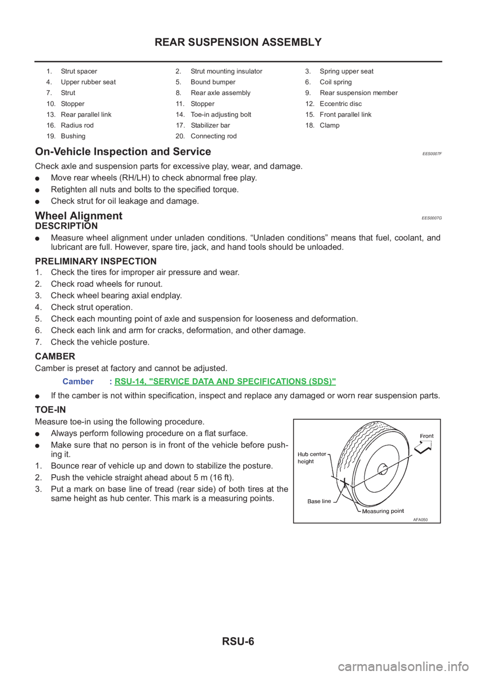
3. Put a mark on base line of tread (rear side) of both tires at the
same height as hub center. This mark is a measuring points.
1. Strut spacer 2. Strut mounting insulator 3. Spring upper seat
4. Upper rubber seat 5. Bound bumper 6. Coil spring
7. Strut 8. Rear axle assembly 9. Rear suspension member
10. Stopper 11. Stopper 12. Eccentric disc
13. Rear parallel link 14. Toe-in adjusting bolt 15. Front parallel link
16. Radius rod 17. Stabilizer bar 18. Clamp
19. Bushing 20. Connecting rod
Camber : RSU-14, "SERVICE DATA AND SPECIFICATIONS (SDS)"
AFA050