2001 NISSAN X-TRAIL wheel bolt torque
[x] Cancel search: wheel bolt torquePage 3 of 3833

GI-1
GENERAL INFORMATION
A GENERAL INFORMATION
CONTENTS
C
D
E
F
G
H
I
J
K
L
MB
GI
SECTION
GENERAL INFORMATION
PRECAUTIONS .......................................................... 3
Description ............................................................... 3
Precautions for Supplemental Restraint System
(SRS) “AIR BAG” and “SEAT BELT PRE-TEN-
SIONER” .................................................................. 3
Precautions for NATS (NISSAN ANTI-THEFT SYS-
TEM) ........................................................................ 3
General Precautions ................................................ 4
Precautions for All Mode 4 × 4 System .................... 5
Precautions for Three Way Catalyst ......................... 5
Precautions for Fuel ................................................. 5
GASOLINE ENGINE ............................................. 5
DIESEL ENGINE ................................................... 5
Precautions for Multiport Fuel Injection System or
Engine Control System ............................................ 6
Precautions for Turbocharger (If Equipped) ............. 6
Precautions for Hoses .............................................. 6
HOSE REMOVAL AND INSTALLATION ............... 6
HOSE CLAMPING ................................................ 7
Precautions for Engine Oils ...................................... 7
HEALTH PROTECTION PRECAUTIONS ............. 7
ENVIRONMENTAL PROTECTION PRECAU-
TIONS ................................................................... 7
Precautions for Air Conditioning ............................... 7
HOW TO USE THIS MANUAL ................................... 8
Description ............................................................... 8
Terms ....................................................................... 8
Units ......................................................................... 8
Contents ................................................................... 8
Components ............................................................. 8
SYMBOLS ............................................................. 9
How to Follow Trouble Diagnoses ............................ 9
DESCRIPTION ...................................................... 9
HOW TO FOLLOW TEST GROUPS IN TROU-
BLE DIAGNOSES ............................................... 10
HARNESS WIRE COLOR AND CONNECTOR
NUMBER INDICATION ........................................ 11
KEY TO SYMBOLS SIGNIFYING MEASURE-
MENTS OR PROCEDURES ............................... 12
How to Read Wiring Diagrams ............................... 14CONNECTOR SYMBOLS ................................... 14
SAMPLE/WIRING DIAGRAM - EXAMPL - .......... 15
DESCRIPTION .................................................... 16
Abbreviations .......................................................... 22
SERVICE INFORMATION FOR ELECTRICAL INCI-
DENT ......................................................................... 23
How to Perform Efficient Diagnosis for an Electrical
Incident ................................................................... 23
WORK FLOW ...................................................... 23
INCIDENT SIMULATION TESTS ........................ 23
CIRCUIT INSPECTION ....................................... 26
Control Units and Electrical Parts ........................
... 31
PRECAUTIONS .................................................. 31
CONSULT-II CHECKING SYSTEM .......................... 33
Description .............................................................. 33
Function and System Application ........................... 33
Nickel Metal Hydride Battery Replacement ............ 33
Checking Equipment .............................................. 34
CONSULT-II Data Link Connector (DLC) Circuit .... 34
INSPECTION PROCEDURE .............................. 34
LIFTING POINT ......................................................... 35
Special Service Tools ............................................. 35
Garage Jack and Safety Stand ............................... 35
2-pole Lift ................................................................ 36
Board-on Lift ........................................................... 37
TOW TRUCK TOWING ............................................. 38
Tow Truck Towing ................................................... 38
TOWING AN AUTOMATIC TRANSAXLE
MODEL WITH FOUR WHEELS ON GROUND ... 38
T O W I N G T H E V E H I C L E W I T H R E A R W H E E L S
R A I S E D ( W I T H F R O N T W H E E L S O N G R O U N D )
OR FRONT WHEELS RAISED ........................... 39
Vehicle Recovery (Freeing a stuck vehicle) ............ 39
TIGHTENING TORQUE OF STANDARD BOLTS .... 40
Tightening Torque Table ......................................... 40
IDENTIFICATION INFORMATION ............................ 41
Model Variation ....................................................... 41
IDENTIFICATION NUMBER ................................ 42
IDENTIFICATION PLATE .................................... 43
ENGINE SERIAL NUMBER ................................ 43
Page 52 of 3833
EM-2
TIMING CHAIN .......................................................... 37
Removal and Installation ........................................ 37
REMOVAL ........................................................... 38
INSPECTION AFTER REMOVAL ........................ 41
INSTALLATION .................................................... 41
CAMSHAFT ............................................................... 46
Removal and Installation ........................................ 46
REMOVAL ........................................................... 46
INSTALLATION .................................................... 48
INSPECTION AFTER REMOVAL ........................ 51
Valve Clearance ...................................................... 53
INSPECTION ....................................................... 53
ADJUSTMENT .................................................... 54
OIL SEAL .................................................................. 56
Removal and Installation of Valve Oil Seal ............. 56
REMOVAL ........................................................... 56
INSTALLATION .................................................... 56
Removal and Installation of Front Oil Seal ............. 56
REMOVAL ........................................................... 56
INSTALLATION .................................................... 57
Removal and Installation of Rear Oil Seal .............. 57
REMOVAL ........................................................... 57
INSTALLATION .................................................... 57
CYLINDER HEAD .................................................. ... 59
On-Vehicle Service ................................................. 59
CHECKING COMPRESSION PRESSURE ......... 59
Removal and Installation ........................................ 60
REMOVAL ........................................................... 60
INSPECTION AFTER REMOVAL ........................ 61
INSTALLATION .................................................... 61
Disassembly and Assembly .................................... 62
DISASSEMBLY ................................................... 63
ASSEMBLY ......................................................... 63
Inspection After Disassembly ................................. 64
CYLINDER HEAD DISTORTION ........................ 64
VALVE DIMENSIONS .......................................... 64
VALVE GUIDE CLEARANCE .............................. 65
VALVE GUIDE REPLACEMENT ......................... 65
VALVE SEAT CONTACT ..................................... 66
VALVE SEAT REPLACEMENT ........................... 66
VALVE SPRING SQUARENESS ......................... 67
VALVE SPRING DIMENSIONS AND VALVE
SPRING PRESSURE LOAD ............................... 68
ENGINE ASSEMBLY ................................................ 69
Removal and Installation ........................................ 69
REMOVAL .......................................................
.... 69
INSTALLATION .................................................... 71
INSPECTION AFTER INSTALLATION ................ 71
CYLINDER BLOCK ................................................... 73
Disassembly and Assembly .................................... 73
DISASSEMBLY ................................................... 74
ASSEMBLY ......................................................... 78
How to Select Piston and Bearing .......................... 82
DESCRIPTION .................................................... 82
HOW TO SELECT PISTON ................................. 83
HOW TO SELECT CONNECTING ROD BEAR-
ING ...................................................................... 83HOW TO SELECT MAIN BEARING .................... 85
Inspection After Disassembly .................................. 88
CRANKSHAFT END PLAY .................................. 88
CONNECTING ROD SIDE CLEARANCE ........... 89
PISTON AND PISTON PIN CLEARANCE ........... 89
PISTON RING SIDE CLEARANCE ..................... 90
PISTON RING END GAP .................................... 90
CONNECTING ROD BEND AND TORSION ....... 91
CONNECTING ROD BEARING (BIG END) ........ 91
CONNECTING ROD BUSHING OIL CLEAR-
ANCE (SMALL END) ........................................... 91
CYLINDER BLOCK DISTORTION ...................... 92
INNER DIAMETER OF MAIN BEARING HOUS-
ING ....................................................................... 93
PISTON TO CYLINDER BORE CLEARANCE .... 93
OUTER DIAMETER OF CRANKSHAFT JOUR-
NAL ...................................................................... 94
OUTER DIAMETER OF CRANKSHAFT PIN ...... 94
OUT-OF-ROUND AND TAPER OF CRANK-
SHAFT ................................................................. 94
CRANKSHAFT RUNOUT .................................... 95
CONNECTING ROD BEARING OIL CLEAR-
ANCE ................................................................... 95
MAIN BEARING OIL CLEARANCE ..................... 95
MAIN BEARING CRUSH HEIGHT ...................... 96
OUTER DIAMETER OF LOWER CYLINDER
BLOCK MOUNTING BOLT .................................. 96
OUTER DIAMETER OF CONNECTING ROD
BOLT .................................................................... 96
MOVEMENT AMOUNT OF FLYWHEEL (M/T
MODELS) ............................................................. 97
SERVICE DATA AND SPECIFICATIONS (SDS) ...... 98
Standard and Limit .................................................. 98
GENERAL SPECIFICATIONS ............................. 98
DRIVE BELTS ...................................................... 98
INTAKE MANIFOLD AND EXHAUST MANI-
FOLD ................................................................... 98
SPARK PLUG ...................................................... 98
CYLINDER HEAD ................................................ 98
VALVE .................................................................. 99
CAMSHAFT AND CAMSHAFT BEARING .........102
CYLINDER BLOCK ............................................102
PISTON, PISTON RING AND PISTON PIN .....
.103
CONNECTING ROD ..........................................104
CRANKSHAFT ...................................................105
MAIN BEARING .................................................106
CONNECTING ROD BEARING .........................107
Tightening Torque .................................................108
YD22DDTi
PRECAUTIONS .......................................................110
Precautions for Drain Engine Coolant ...................110
Precautions for Disconnecting Fuel Piping ...........110
Precautions for Removal and Disassembly ..........110
Precautions for Inspection, Repair and Replace-
ment ......................................................................110
Precautions for Assembly and Installation ............110
Page 54 of 3833
EM-4
INSPECTION AFTER REMOVAL ......................184
INSTALLATION ..................................................185
Disassembly and Assembly ..................................187
DISASSEMBLY .................................................187
ASSEMBLY .......................................................188
INSPECTION AFTER DISASSEMBLY ..............188
ENGINE ASSEMBLY ..............................................193
Removal and Installation ......................................193
REMOVAL .........................................................194
INSTALLATION ..................................................195
INSPECTION AFTER INSTALLATION ..............196
CYLINDER BLOCK .................................................197
Disassembly and Assembly ..................................197
DISASSEMBLY .................................................198
ASSEMBLY .......................................................202
How to Select Piston and Bearing ........................206
DESCRIPTION ..................................................206
HOW TO SELECT PISTON ...............................206
HOW TO SELECT CONNECTING ROD BEAR-
ING ....................................................................207
HOW TO SELECT MAIN BEARING ..................208
Inspection After Disassembly ...............................210
CRANKSHAFT END PLAY ................................210
CONNECTING ROD SIDE CLEARANCE .........210
PISTON TO PISTON PIN CLEARANCE ...........210
PISTON RING SIDE CLEARANCE ...................211
PISTON RING END GAP ..................................211
CONNECTING ROD BEND AND TORSION .....212
CONNECTING ROD BIG END INNER DIAME-
TER ...................................................................212
CONNECTING ROD BUSHING OIL CLEAR-
ANCE (SMALL END) .........................................212
CYLINDER BLOCK TOP SURFACE DISTOR-TION ..................................................................213
MAIN BEARING HOUSING INNER DIAMETER .213
PISTON TO CYLINDER BORE CLEARANCE ..214
CRANKSHAFT JOURNAL OUTER DIAMETER .215
CRANKSHAFT PIN OUTER DIAMETER ..........215
CRANKSHAFT OUT-OF-ROUND AND TAPER .215
CRANKSHAFT RUNOUT ..................................216
CONNECTING ROD BEARING OIL CLEAR-
ANCE .................................................................216
MAIN BEARING OIL CLEARANCE ...................216
MAIN BEARING CRUSH HEIGHT ....................217
MAIN BEARING CAP BOLT DEFORMATION ...217
CONNECTING ROD BOLT DEFORMATION ....217
OIL JET ..............................................................218
OIL JET RELIEF VALVE ....................................218
MOVEMENT AMOUNT OF FLYWHEEL ...........218
SERVICE DATA AND SPECIFICATIONS (SDS) ....220
Standard and Limit ...............................................
.220
GENERAL SPECIFICATIONS ...........................220
INTAKE MANIFOLD AND EXHAUST MANI-
FOLD .................................................................220
DRIVE BELTS ....................................................220
CYLINDER HEAD ..............................................221
VALVE ................................................................221
CAMSHAFT AND CAMSHAFT BEARING .........225
CYLINDER BLOCK ............................................225
PISTON, PISTON RING AND PISTON PIN ......226
CONNECTING ROD ..........................................227
CRANKSHAFT ...................................................227
AVAILABLE MAIN BEARING .............................228
AVAILABLE CONNECTING ROD BEARING .....228
MISCELLANEOUS COMPONENTS ..................228
Tightening Torque .................................................229
Page 147 of 3833
![NISSAN X-TRAIL 2001 Service Repair Manual CYLINDER BLOCK
EM-97
[QR]
C
D
E
F
G
H
I
J
K
L
MA
EM
MOVEMENT AMOUNT OF FLYWHEEL (M/T MODELS)
NOTE:
●Inspection for double mass flywheel only.
●Do not disassembly double mass flywheel.
Flywheel Def NISSAN X-TRAIL 2001 Service Repair Manual CYLINDER BLOCK
EM-97
[QR]
C
D
E
F
G
H
I
J
K
L
MA
EM
MOVEMENT AMOUNT OF FLYWHEEL (M/T MODELS)
NOTE:
●Inspection for double mass flywheel only.
●Do not disassembly double mass flywheel.
Flywheel Def](/manual-img/5/57405/w960_57405-146.png)
CYLINDER BLOCK
EM-97
[QR]
C
D
E
F
G
H
I
J
K
L
MA
EM
MOVEMENT AMOUNT OF FLYWHEEL (M/T MODELS)
NOTE:
●Inspection for double mass flywheel only.
●Do not disassembly double mass flywheel.
Flywheel Deflection
●Measure deflection of flywheel contact surface to the clutch with a dial gauge.
●Measure deflection at 210 mm (8.27 in) dia.
●When measured value exceeds the limit, replace it with a new
one.
Movement Amount in Radial (rotation) Direction
Check the movement amount in the following procedure.
1. Install a bolt to clutch cover mounting hole, and place a torque wrench on the extended line of the flywheel
center line.
●Tighten bolt at a force of 9.8 N·m (1.0 kg-m, 87 in-lb) to keep it from loosening.
2. Put a mating mark on circumferences of the two flywheel
masses without applying any load (Measurement standard
points).
3. Apply a force of 9.8 N·m (1.0 kg-m, 87 in-lb) in each direction,
and mark the movement amount on the mass on the transaxle
side.
4. Measure dimensions of movement amounts A and B on circum-
ference of the flywheel on the transaxle side.
●When measured value is outside the standard, replace fly-
wheel.Standard : 0.45 mm (0.0177 in) or less.
Limit : 1.3 mm (0.051 in) or less.
SBIA0287E
Standard: 28.3 mm (1.114 in) or less.
PBIC1263E
Page 268 of 3833
![NISSAN X-TRAIL 2001 Service Repair Manual EM-218
[YD22DDTi]
CYLINDER BLOCK
OIL JET
●Check nozzle for deformation and damage.
●Blow compressed air from nozzle, and check for clogs.
●If it out of the standard, replace oil jet.
OIL JET REL NISSAN X-TRAIL 2001 Service Repair Manual EM-218
[YD22DDTi]
CYLINDER BLOCK
OIL JET
●Check nozzle for deformation and damage.
●Blow compressed air from nozzle, and check for clogs.
●If it out of the standard, replace oil jet.
OIL JET REL](/manual-img/5/57405/w960_57405-267.png)
EM-218
[YD22DDTi]
CYLINDER BLOCK
OIL JET
●Check nozzle for deformation and damage.
●Blow compressed air from nozzle, and check for clogs.
●If it out of the standard, replace oil jet.
OIL JET RELIEF VALVE
●Using a clean plastic stick, press check valve in oil jet relief
valve. Make sure that valve moves smoothly with proper reac-
tion force.
●If it is out of the standard, replace oil jet relief valve.
MOVEMENT AMOUNT OF FLYWHEEL
NOTE:
●Inspection for double mass flywheel only.
●Do not disassembly double mass flywheel.
Flywheel Deflection
●Measure deflection of flywheel contact surface to the clutch with a dial gauge.
●Measure deflection at 210 mm (8.27 in) dia.
●When measured value exceeds the limit, replace flywheel with a
new one.
Movement Amount in Radial (rotation) Direction
Check the movement amount in the following procedure.
1. Install a bolt to clutch cover mounting hole, and place a torque wrench on the extended line of the flywheel
center line.
●Tighten bolt at a force of 9.8 N·m (1 kg-m, 87 in-lb) to keep it from loosening. Standard : Deformation and damage.
JEM221G
Standard:
Valve moves smoothly with proper reaction force.
JEM222G
Standard : 0.45 mm (0.0177 in) or less
Limit : 1.3 mm (0.051 in)
PBIC0683E
Page 2678 of 3833
RFD-2
PRECAUTIONS
PRECAUTIONS
PFP:00001
CautionEDS00101
●Before starting diagnosis of the vehicle, understand symptoms well. Perform correct and systematic oper-
ations.
●Check for the correct installation status prior to removal or disassembly. When mating marks are required,
be sure they do not interfere with the function of the parts they are applied to.
●Carry out an overhaul in a clean work place. Using a dust proof room is recommended.
●Before disassembly, using steam or white gasoline, completely remove sand and mud from the exterior of
the unit, preventing them from entering into the unit during disassembly or assembly.
●Check appearance of the disassembled parts for damage, deformation, and abnormal wear. If a malfunc-
tion is detected, replace it with a new one.
●Normally replace lock pins, oil seals, and bearings with new ones every time they are removed.
●In principle, tighten bolts or nuts gradually in several steps working diagonally from inside to outside. If
tightening sequence is specified, observe it.
●Clean and flush the parts sufficiently and blow them dry.
●Be careful not to damage the sliding surfaces and mating surfaces.
●When applying sealant, remove the old sealant from the mounting surface; then remove any moisture, oil,
and foreign materials from the application and mounting surfaces.
●Always use shop paper for cleaning the inside of components.
●Avoid using cotton gloves or a shop cloth to prevent entering of lint.
●During assembly, observe the specified tightening torque, and apply new differential oil, Vaseline, or Nis-
san MP Special Grease No. 2, as specified for each vehicle, when necessary.
●Do not reuse drained oil. Discard waste oil after oil changes or part treatment in accordance with local
laws and regulations.
Precautions for Brake SystemEDS00102
●When installing rubber parts, final tightening must be carried out under unladen condition* with tires on
ground.
*: Fuel, radiator coolant and engine oil full. Spare tire, jack, hand tools and mats in designated positions.
●After installing removed suspension parts, check wheel alignment and adjust if necessary.
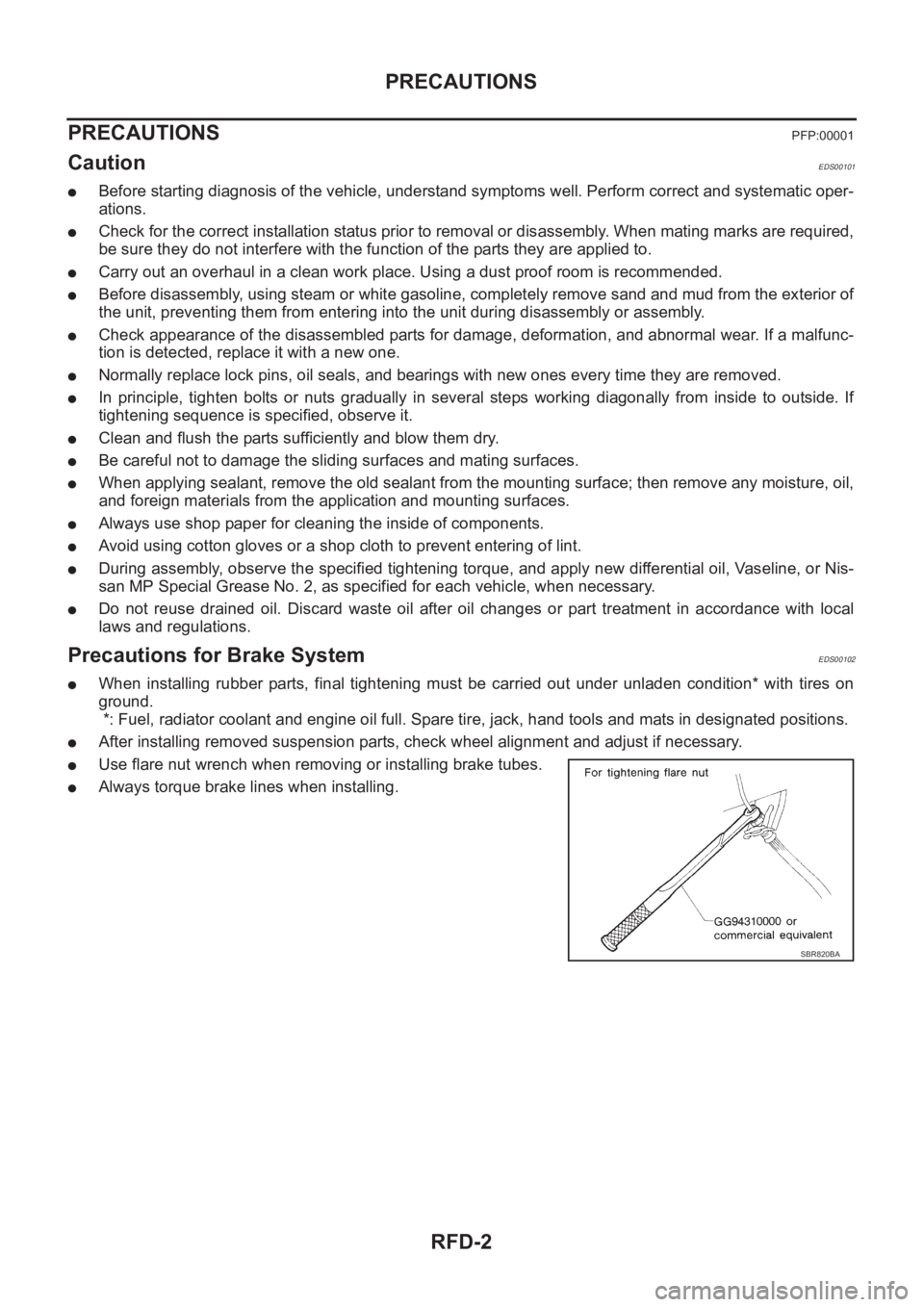
●Use flare nut wrench when removing or installing brake tubes.
●Always torque brake lines when installing.
SBR820BA
Page 2709 of 3833
PREPARATION
FSU-3
C
D
F
G
H
I
J
K
L
MA
B
FSU
PREPARATIONPFP:00002
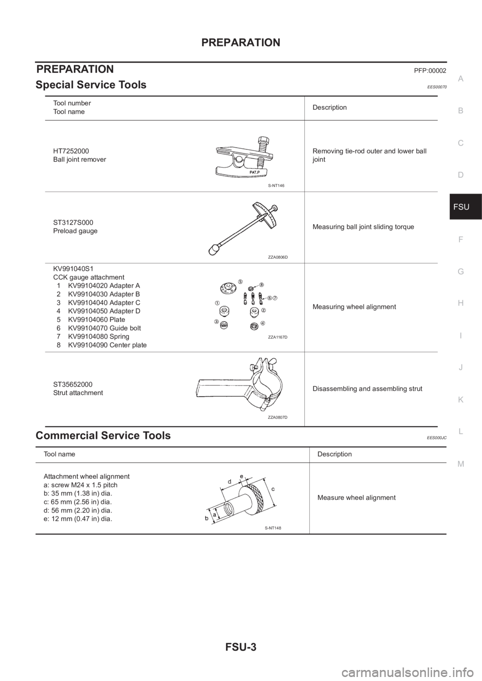
Special Service ToolsEES00070
Commercial Service ToolsEES000JC
Tool number
Tool nameDescription
HT7252000
Ball joint removerRemoving tie-rod outer and lower ball
joint
ST3127S000
Preload gaugeMeasuring ball joint sliding torque
KV991040S1
CCK gauge attachment
1 KV99104020 Adapter A
2 KV99104030 Adapter B
3 KV99104040 Adapter C
4 KV99104050 Adapter D
5 KV99104060 Plate
6 KV99104070 Guide bolt
7 KV99104080 Spring
8 KV99104090 Center plateMeasuring wheel alignment
ST35652000
Strut attachmentDisassembling and assembling strut
S-NT146
ZZA0806D
ZZA1167D
ZZA0807D
To o l n a m eDescription
Attachment wheel alignment
a: screw M24 x 1.5 pitch
b: 35 mm (1.38 in) dia.
c: 65 mm (2.56 in) dia.
d: 56 mm (2.20 in) dia.
e: 12 mm (0.47 in) dia.Measure wheel alignment
S-NT148
Page 2714 of 3833
FSU-8
COIL SPRING AND SHOCK ABSORBER
COIL SPRING AND SHOCK ABSORBER
PFP:54302
Removal and InstallationEES00074
REMOVAL
1. Remove tires. Remove brake caliper and hung it aside.
CAUTION:
Avoid depressing brake pedal with brake caliper removed.
2. Remove electrical wires of ABS wheel speed sensor from strut.
3. Remove brake hose lock plate.
4. Remove mounting bolts and nuts securing steering knuckle to strut.
5. Remove mounting nuts on upper mounting plate and remove upper mounting plate and strut from vehicle.
INSTALLATION
●Refer to FSU-5, "Components" in “Front Suspension Assembly” for tightening torque. Tighten in the
reverse order of removal.
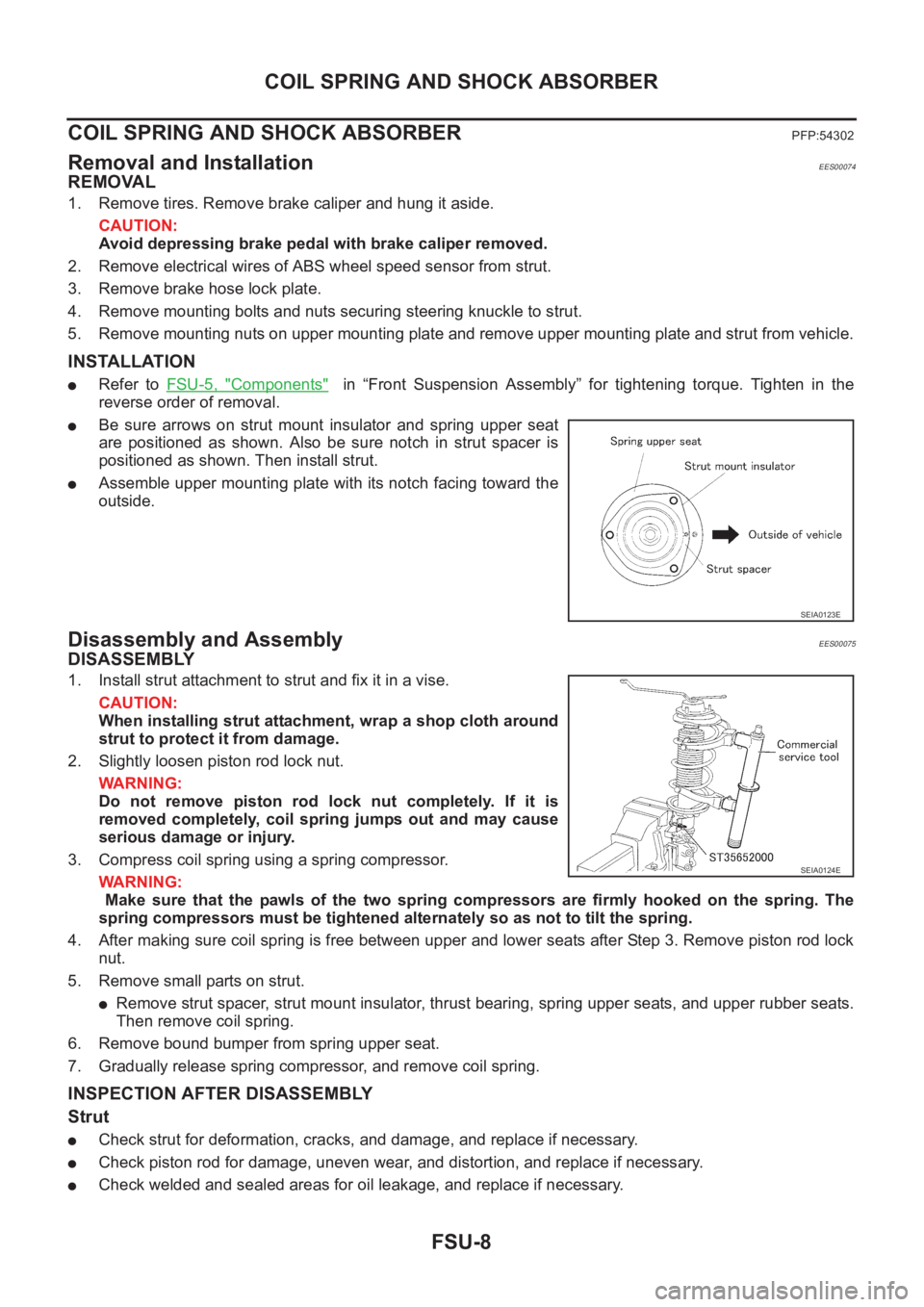
●Be sure arrows on strut mount insulator and spring upper seat
are positioned as shown. Also be sure notch in strut spacer is
positioned as shown. Then install strut.
●Assemble upper mounting plate with its notch facing toward the
outside.
Disassembly and AssemblyEES00075
DISASSEMBLY
1. Install strut attachment to strut and fix it in a vise.
CAUTION:
When installing strut attachment, wrap a shop cloth around
strut to protect it from damage.
2. Slightly loosen piston rod lock nut.
WARNING:
Do not remove piston rod lock nut completely. If it is
removed completely, coil spring jumps out and may cause
serious damage or injury.
3. Compress coil spring using a spring compressor.
WARNING:
Make sure that the pawls of the two spring compressors are firmly hooked on the spring. The
spring compressors must be tightened alternately so as not to tilt the spring.
4. After making sure coil spring is free between upper and lower seats after Step 3. Remove piston rod lock
nut.
5. Remove small parts on strut.
●Remove strut spacer, strut mount insulator, thrust bearing, spring upper seats, and upper rubber seats.
Then remove coil spring.
6. Remove bound bumper from spring upper seat.
7. Gradually release spring compressor, and remove coil spring.
INSPECTION AFTER DISASSEMBLY
Strut
●Check strut for deformation, cracks, and damage, and replace if necessary.
●Check piston rod for damage, uneven wear, and distortion, and replace if necessary.
●Check welded and sealed areas for oil leakage, and replace if necessary.
SEIA0123E
SEIA0124E