2001 NISSAN X-TRAIL Nats system
[x] Cancel search: Nats systemPage 3 of 3833

GI-1
GENERAL INFORMATION
A GENERAL INFORMATION
CONTENTS
C
D
E
F
G
H
I
J
K
L
MB
GI
SECTION
GENERAL INFORMATION
PRECAUTIONS .......................................................... 3
Description ............................................................... 3
Precautions for Supplemental Restraint System
(SRS) “AIR BAG” and “SEAT BELT PRE-TEN-
SIONER” .................................................................. 3
Precautions for NATS (NISSAN ANTI-THEFT SYS-
TEM) ........................................................................ 3
General Precautions ................................................ 4
Precautions for All Mode 4 × 4 System .................... 5
Precautions for Three Way Catalyst ......................... 5
Precautions for Fuel ................................................. 5
GASOLINE ENGINE ............................................. 5
DIESEL ENGINE ................................................... 5
Precautions for Multiport Fuel Injection System or
Engine Control System ............................................ 6
Precautions for Turbocharger (If Equipped) ............. 6
Precautions for Hoses .............................................. 6
HOSE REMOVAL AND INSTALLATION ............... 6
HOSE CLAMPING ................................................ 7
Precautions for Engine Oils ...................................... 7
HEALTH PROTECTION PRECAUTIONS ............. 7
ENVIRONMENTAL PROTECTION PRECAU-
TIONS ................................................................... 7
Precautions for Air Conditioning ............................... 7
HOW TO USE THIS MANUAL ................................... 8
Description ............................................................... 8
Terms ....................................................................... 8
Units ......................................................................... 8
Contents ................................................................... 8
Components ............................................................. 8
SYMBOLS ............................................................. 9
How to Follow Trouble Diagnoses ............................ 9
DESCRIPTION ...................................................... 9
HOW TO FOLLOW TEST GROUPS IN TROU-
BLE DIAGNOSES ............................................... 10
HARNESS WIRE COLOR AND CONNECTOR
NUMBER INDICATION ........................................ 11
KEY TO SYMBOLS SIGNIFYING MEASURE-
MENTS OR PROCEDURES ............................... 12
How to Read Wiring Diagrams ............................... 14CONNECTOR SYMBOLS ................................... 14
SAMPLE/WIRING DIAGRAM - EXAMPL - .......... 15
DESCRIPTION .................................................... 16
Abbreviations .......................................................... 22
SERVICE INFORMATION FOR ELECTRICAL INCI-
DENT ......................................................................... 23
How to Perform Efficient Diagnosis for an Electrical
Incident ................................................................... 23
WORK FLOW ...................................................... 23
INCIDENT SIMULATION TESTS ........................ 23
CIRCUIT INSPECTION ....................................... 26
Control Units and Electrical Parts ........................
... 31
PRECAUTIONS .................................................. 31
CONSULT-II CHECKING SYSTEM .......................... 33
Description .............................................................. 33
Function and System Application ........................... 33
Nickel Metal Hydride Battery Replacement ............ 33
Checking Equipment .............................................. 34
CONSULT-II Data Link Connector (DLC) Circuit .... 34
INSPECTION PROCEDURE .............................. 34
LIFTING POINT ......................................................... 35
Special Service Tools ............................................. 35
Garage Jack and Safety Stand ............................... 35
2-pole Lift ................................................................ 36
Board-on Lift ........................................................... 37
TOW TRUCK TOWING ............................................. 38
Tow Truck Towing ................................................... 38
TOWING AN AUTOMATIC TRANSAXLE
MODEL WITH FOUR WHEELS ON GROUND ... 38
T O W I N G T H E V E H I C L E W I T H R E A R W H E E L S
R A I S E D ( W I T H F R O N T W H E E L S O N G R O U N D )
OR FRONT WHEELS RAISED ........................... 39
Vehicle Recovery (Freeing a stuck vehicle) ............ 39
TIGHTENING TORQUE OF STANDARD BOLTS .... 40
Tightening Torque Table ......................................... 40
IDENTIFICATION INFORMATION ............................ 41
Model Variation ....................................................... 41
IDENTIFICATION NUMBER ................................ 42
IDENTIFICATION PLATE .................................... 43
ENGINE SERIAL NUMBER ................................ 43
Page 35 of 3833

CONSULT-II CHECKING SYSTEM
GI-33
C
D
E
F
G
H
I
J
K
L
MB
GI
CONSULT-II CHECKING SYSTEMPFP:00000
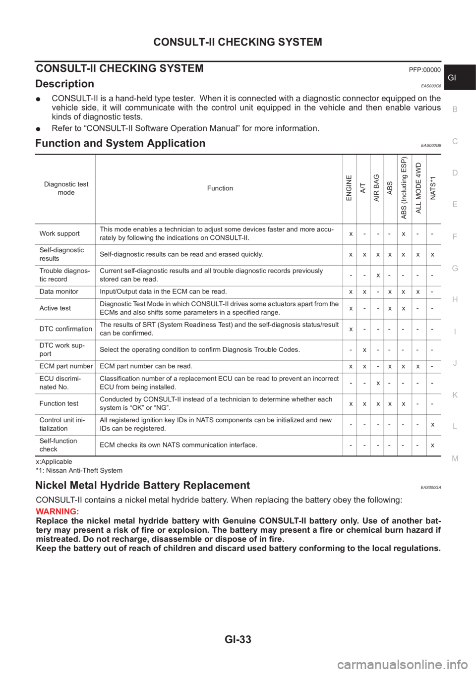
DescriptionEAS000G8
●CONSULT-II is a hand-held type tester. When it is connected with a diagnostic connector equipped on the
vehicle side, it will communicate with the control unit equipped in the vehicle and then enable various
kinds of diagnostic tests.
●Refer to “CONSULT-II Software Operation Manual” for more information.
Function and System Application EAS000G9
x:Applicable
*1: Nissan Anti-Theft System
Nickel Metal Hydride Battery Replacement EAS000GA
CONSULT-II contains a nickel metal hydride battery. When replacing the battery obey the following:
WARNING:
Replace the nickel metal hydride battery with Genuine CONSULT-II battery only. Use of another bat-
tery may present a risk of fire or explosion. The battery may present a fire or chemical burn hazard if
mistreated. Do not recharge, disassemble or dispose of in fire.
Keep the battery out of reach of children and discard used battery conforming to the local regulations.
Diagnostic test
modeFunction
ENGINE
A/T
AIR BAG
ABS
ABS (Including ESP)
ALL MODE 4WD
NATS*1
Work supportThis mode enables a technician to adjust some devices faster and more accu-
rately by following the indications on CONSULT-II.x- -- x- -
Self-diagnostic
resultsSelf-diagnostic results can be read and erased quickly. x x x x x x x
Trouble diagnos-
tic recordCurrent self-diagnostic results and all trouble diagnostic records previously
stored can be read.--x----
Data monitor Input/Output data in the ECM can be read. x x - x x x -
Active testDiagnostic Test Mode in which CONSULT-II drives some actuators apart from the
ECMs and also shifts some parameters in a specified range.x- -xx- -
DTC confirmationThe results of SRT (System Readiness Test) and the self-diagnosis status/result
can be confirmed.x------
DTC work sup-
portSelect the operating condition to confirm Diagnosis Trouble Codes. -x-----
ECM part number ECM part number can be read. x x - x x x -
ECU discrimi-
nated No.Classification number of a replacement ECU can be read to prevent an incorrect
ECU from being installed.--x----
Function testConducted by CONSULT-II instead of a technician to determine whether each
system is “OK” or “NG”.xxxxx - -
Control unit ini-
tializationAll registered ignition key IDs in NATS components can be initialized and new
IDs can be registered.------x
Self-function
checkECM checks its own NATS communication interface. - - - - - - x
Page 36 of 3833

GI-34
CONSULT-II CHECKING SYSTEM
Checking Equipment
EAS000GB
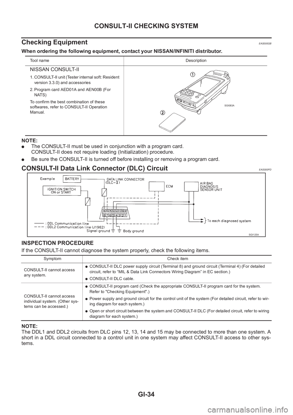
When ordering the following equipment, contact your NISSAN/INFINITI distributor.
NOTE:
●The CONSULT-II must be used in conjunction with a program card.
CONSULT-II does not require loading (Initialization) procedure.
●Be sure the CONSULT-II is turned off before installing or removing a program card.
CONSULT-II Data Link Connector (DLC) CircuitEAS000PD
INSPECTION PROCEDURE
If the CONSULT-II cannot diagnose the system properly, check the following items.
NOTE:
The DDL1 and DDL2 circuits from DLC pins 12, 13, 14 and 15 may be connected to more than one system. A
short in a DDL circuit connected to a control unit in one system may affect CONSULT-II access to other sys-
tems.
To o l n a m eDescription
NISSAN CONSULT-II
1. CONSULT-II unit (Tester internal soft: Resident
version 3.3.0) and accessories
2. Program card AED01A and AEN00B (For
NATS)
To confirm the best combination of these
softwares, refer to CONSULT-II Operation
Manual.
SGI083A
SGI125A
Symptom Check item
CONSULT-II cannot access
any system.
●CONSULT-II DLC power supply circuit (Terminal 8) and ground circuit (Terminal 4) (For detailed
circuit, refer to “MIL & Data Link Connectors Wiring Diagram” in EC section.)
●CONSULT-II DLC cable.
CONSULT-II cannot access
individual system. (Other sys-
tems can be accessed.)
●CONSULT-II program card (Check the appropriate CONSULT-II program card for the system.
Refer to "Checking Equipment".)
●Power supply and ground circuit for the control unit of the system (For detailed circuit, refer to wir-
ing diagram for each system.)
●Open or short circuit between the system and CONSULT-II DLC (For detailed circuit, refer to wiring
diagram for each system.)
Page 351 of 3833

EC-1
ENGINE CONTROL SYSTEM
B ENGINE
CONTENTS
C
D
E
F
G
H
I
J
K
L
M
SECTION
A
EC
ENGINE CONTROL SYSTEM
QR25(WITH EURO-OBD)
INDEX FOR DTC ...................................................... 20
Alphabetical Index .................................................. 20
DTC No. Index ....................................................... 22
PRECAUTIONS ........................................................ 25
Precautions for Supplemental Restraint System
(SRS) “AIR BAG” and “SEAT BELT PRE-TEN-
SIONER” ................................................................ 25
On Board Diagnostic (OBD) System of Engine and
A/T .......................................................................... 25
Precaution .............................................................. 25
Wiring Diagrams and Trouble Diagnosis ................ 28
PREPARATION ......................................................... 29
Special Service Tools ............................................. 29
Commercial Service Tools ...................................... 29
ENGINE CONTROL SYSTEM .................................. 31
System Diagram ..................................................... 31
Vacuum Hose Drawing ........................................... 32
System Chart ......................................................... 33
Multiport Fuel Injection (MFI) System .................... 33
Electronic Ignition (EI) System ............................... 35
Air Conditioning Cut Control ................................... 36
Fuel Cut Control (at No Load and High Engine
Speed) .................................................................... 37
CAN Communication .............................................. 37
BASIC SERVICE PROCEDURE .............................. 38
Idle Speed and Ignition Timing Check .................... 38
Accelerator Pedal Released Position Learning ...... 39
Throttle Valve Closed Position Learning ................ 39
Idle Air Volume Learning ........................................ 39
Fuel Pressure Check .............................................. 42
ON BOARD DIAGNOSTIC (OBD) SYSTEM ............ 44
Introduction ............................................................ 44
Two Trip Detection Logic ........................................ 44
Emission-related Diagnostic Information ................ 45
NATS (Nissan Anti-theft System) ........................... 58
Malfunction Indicator (MI) ....................................... 58
OBD System Operation Chart ................................ 61
TROUBLE DIAGNOSIS ............................................ 67
Trouble Diagnosis Introduction ............................... 67DTC Inspection Priority Chart ................................. 70
Fail-safe Chart ........................................................ 71
Basic Inspection ..................................................... 73
Symptom Matrix Chart ............................................ 77
Engine Control Component Parts Location ............ 81
Circuit Diagram ....................................................... 85
ECM Harness Connector Terminal Layout ............. 87
ECM Terminals and Reference Value ..................
... 87
CONSULT-II Function ............................................. 94
Generic Scan Tool (GST) Function .......................104
CONSULT-II Reference Value in Data Monitor .....106
Major Sensor Reference Graph in Data Monitor
Mode .....................................................................109
TROUBLE DIAGNOSIS - SPECIFICATION VALUE ..111
Description .............................................................111
Testing Condition ...................................................111
Inspection Procedure .............................................111
Diagnostic Procedure ...........................................112
TROUBLE DIAGNOSIS FOR INTERMITTENT INCI-
DENT .......................................................................115
Description ............................................................115
Diagnostic Procedure ...........................................115
POWER SUPPLY CIRCUIT FOR ECM ...................116
Wiring Diagram .....................................................116
ECM Terminals and Reference Value ...................117
Diagnostic Procedure ...........................................117
Component Inspection ..........................................121
DTC U1000 CAN COMMUNICATION LINE ............122
Description ............................................................122
On Board Diagnosis Logic ....................................122
DTC Confirmation Procedure ...............................122
Wiring Diagram .....................................................123
Diagnostic Procedure ...........................................124
DTC P0011 IVT CONTROL .....................................125
Description ............................................................125
CONSULT-II Reference Value in Data Monitor Mode
.125
ECM Terminals and Reference Value ...................125
On Board Diagnosis Logic ....................................126
Page 356 of 3833

EC-6
DATA LINK CONNECTOR ......................................424
Wiring Diagram .....................................................424
EVAPORATIVE EMISSION SYSTEM .....................425
Description ............................................................425
Component Inspection ..........................................427
POSITIVE CRANKCASE VENTILATION ...............428
Description ............................................................428
Component Inspection ..........................................428
SERVICE DATA AND SPECIFICATIONS (SDS) ....430
Fuel Pressure .......................................................430
Idle Speed and Ignition Timing .............................430
Calculated Load Value ..........................................430
Mass Air Flow Sensor ...........................................430
Intake Air Temperature Sensor .............................430
Engine Coolant Temperature Sensor ...................430
Heated Oxygen Sensor 1 Heater .........................430
Heated Oxygen sensor 2 Heater ..........................430
Crankshaft Position Sensor (POS) .......................430
Camshaft Position Sensor (PHASE) ....................431
Throttle Control Motor ...........................................431
Injector ..................................................................431
Fuel Pump ............................................................431
QR25(WITHOUT EURO-OBD)
INDEX FOR DTC .....................................................432
Alphabetical Index ................................................432
DTC No. Index ......................................................433
PRECAUTIONS .......................................................435
Precautions for Supplemental Restraint System
(SRS) “AIR BAG” and “SEAT BELT PRE-TEN-
SIONER” ...............................................................435
On Board Diagnostic (OBD) System of Engine and
A/T ........................................................................435
Precaution ............................................................435
Wiring Diagrams and Trouble Diagnosis ..............438
PREPARATION .......................................................439
Special Service Tools ...........................................439
Commercial Service Tools ....................................439
ENGINE CONTROL SYSTEM ................................441
System Diagram ...................................................441
Vacuum Hose Drawing .........................................442
System Chart ........................................................443
Multiport Fuel Injection (MFI) System ...................443
Electronic Ignition (EI) System .............................445
Air Conditioning Cut Control .................................446
Fuel Cut Control (at No Load and High Engine
Speed) ..................................................................447
CAN Communication ............................................447
BASIC SERVICE PROCEDURE .............................448
Idle Speed and Ignition Timing Check ..................448
Accelerator Pedal Released Position Learning ....449
Throttle Valve Closed Position Learning ...............449
Idle Air Volume Learning ......................................450
Fuel Pressure Check ............................................452
ON BOARD DIAGNOSTIC (OBD) SYSTEM ..........454
Introduction ...........................................................454
Two Trip Detection Logic ......................................454
Emission-related Diagnostic Information ..............454NATS (Nissan Anti-theft System) ..........................456
Malfunction Indicator (MI) .....................................457
TROUBLE DIAGNOSIS ..........................................460
Trouble Diagnosis Introduction .............................460
DTC Inspection Priority Chart ...............................463
Fail-safe Chart ......................................................464
Basic Inspection ....................................................465
Symptom Matrix Chart ..........................................469
Engine Control Component Parts Location ...........473
Circuit Diagram .....................................................477
ECM Harness Connector Terminal Layout ............479
ECM Terminals and Reference Value ...................479
CONSULT-II Function ...........................................486
CONSULT-II Reference Value in Data Monitor .....496
Major Sensor Reference Graph in Data Monitor
Mode .....................................................................499
TROUBLE DIAGNOSIS - SPECIFICATION VALUE .502
Description ............................................................502
Testing Condition ..................................................502
Inspection Procedure ........................................... .502
Diagnostic Procedure ............................................503
TROUBLE DIAGNOSIS FOR INTERMITTENT INCI-
DENT .......................................................................506
Description ............................................................506
Diagnostic Procedure ............................................506
POWER SUPPLY CIRCUIT FOR ECM ...................507
Wiring Diagram .....................................................507
ECM Terminals and Reference Value ...................508
Diagnostic Procedure ............................................508
Component Inspection ..........................................512
DTC U1000 CAN COMMUNICATION LINE ............513
Description ............................................................513
On Board Diagnosis Logic ....................................513
DTC Confirmation Procedure ................................513
Wiring Diagram .....................................................514
Diagnostic Procedure ............................................515
DTC P0102, P0103 MAF SENSOR .........................516
Component Description ........................................516
CONSULT-II Reference Value in Data Monitor Mode
.516
ECM Terminals and Reference Value ...................516
On Board Diagnosis Logic ....................................516
DTC Confirmation Procedure ................................517
Wiring Diagram .....................................................519
Diagnostic Procedure ............................................520
Component Inspection ..........................................522
Removal and Installation .......................................522
DTC P0117, P0118 ECT SENSOR ..........................523
Component Description ........................................523
On Board Diagnosis Logic ....................................523
DTC Confirmation Procedure ................................524
Wiring Diagram .....................................................525
Diagnostic Procedure ............................................526
Component Inspection ..........................................527
Removal and Installation .......................................527
DTC P0122, P0123 TP SENSOR ............................528
Component Description ........................................528
CONSULT-II Reference Value in Data Monitor Mode
.528
Page 360 of 3833

EC-10
Injector ..................................................................752
Fuel Pump ............................................................752
QR20(WITH EURO-OBD)
INDEX FOR DTC .....................................................753
Alphabetical Index ................................................753
DTC No. Index ......................................................755
PRECAUTIONS .......................................................757
Precautions for Supplemental Restraint System
(SRS) “AIR BAG” and “SEAT BELT PRE-TEN-
SIONER” ...............................................................757
On Board Diagnostic (OBD) System of Engine and
A/T ........................................................................757
Precaution ............................................................757
Wiring Diagrams and Trouble Diagnosis ..............760
PREPARATION .......................................................761
Special Service Tools ...........................................761
Commercial Service Tools ....................................761
ENGINE CONTROL SYSTEM ................................763
System Diagram ...................................................763
Vacuum Hose Drawing .........................................764
System Chart ........................................................765
Multiport Fuel Injection (MFI) System ...................765
Electronic Ignition (EI) System .............................768
Air Conditioning Cut Control .................................768
Fuel Cut Control (at No Load and High Engine
Speed) ..................................................................769
CAN Communication ............................................769
BASIC SERVICE PROCEDURE .............................771
Idle Speed and Ignition Timing Check ..................771
Accelerator Pedal Released Position Learning ....772
Throttle Valve Closed Position Learning ...............772
Idle Air Volume Learning ......................................772
Fuel Pressure Check ............................................775
ON BOARD DIAGNOSTIC (OBD) SYSTEM ..........777
Introduction ...........................................................777
Two Trip Detection Logic ......................................777
Emission-related Diagnostic Information ..............778
NATS (Nissan Anti-theft System) ..........................790
Malfunction Indicator (MI) .....................................790
OBD System Operation Chart ..............................793
TROUBLE DIAGNOSIS ..........................................799
Trouble Diagnosis Introduction .............................799
DTC Inspection Priority Chart ...............................802
Fail-safe Chart ......................................................803
Basic Inspection ...................................................805
Symptom Matrix Chart ..........................................809
Engine Control Component Parts Location ..........813
Circuit Diagram .....................................................817
ECM Harness Connector Terminal Layout ...........819
ECM Terminals and Reference Value ...................819
CONSULT-II Function ...........................................826
Generic Scan Tool (GST) Function .......................836
CONSULT-II Reference Value in Data Monitor .....838
Major Sensor Reference Graph in Data Monitor
Mode .....................................................................840
TROUBLE DIAGNOSIS - SPECIFICATION VALUE .843
Description ............................................................843Testing Condition ..................................................843
Inspection Procedure ........................................... .843
Diagnostic Procedure ............................................844
TROUBLE DIAGNOSIS FOR INTERMITTENT INCI-
DENT .......................................................................847
Description ............................................................847
Diagnostic Procedure ............................................847
POWER SUPPLY CIRCUIT FOR ECM ...................848
Wiring Diagram .....................................................848
ECM Terminals and Reference Value ...................849
Diagnostic Procedure ............................................849
Component Inspection ..........................................853
DTC U1000 CAN COMMUNICATION LINE ............854
Description ............................................................854
On Board Diagnosis Logic ....................................854
DTC Confirmation Procedure ................................854
Wiring Diagram .....................................................855
Diagnostic Procedure ............................................856
DTC P0011 IVT CONTROL .....................................857
Description ............................................................857
CONSULT-II Reference Value in Data Monitor Mode
.857
ECM Terminals and Reference Value ...................857
On Board Diagnosis Logic ....................................858
DTC Confirmation Procedure ................................858
Diagnostic Procedure ............................................859
DTC P0031, P0032 HO2S1 HEATER ......................860
Description ............................................................860
CONSULT-II Reference Value in Data Monitor Mode
.860
ECM Terminals and Reference Value ...................860
On Board Diagnosis Logic ....................................861
DTC Confirmation Procedure ................................861
Wiring Diagram .....................................................862
Diagnostic Procedure ............................................863
Component Inspection ..........................................864
Removal and Installation .......................................864
DTC P0037, P0038 HO2S2 HEATER .....................
.865
Description ............................................................865
CONSULT-II Reference Value in Data Monitor Mode
.865
ECM Terminals and Reference Value ...................865
On Board Diagnosis Logic ....................................866
DTC Confirmation Procedure ................................866
Wiring Diagram .....................................................867
Diagnostic Procedure ............................................868
Component Inspection ..........................................869
Removal and Installation .......................................869
DTC P0102, P0103 MAF SENSOR .........................870
Component Description ........................................870
CONSULT-II Reference Value in Data Monitor Mode
.870
ECM Terminals and Reference Value ...................870
On Board Diagnosis Logic ....................................870
DTC Confirmation Procedure ................................871
Wiring Diagram .....................................................872
Diagnostic Procedure ............................................873
Component Inspection ..........................................874
Removal and Installation .......................................875
Page 364 of 3833

EC-14
Component Inspection .........................................1097
Removal and Installation .....................................1098
REFRIGERANT PRESSURE SENSOR .................1099
Component Description .......................................1099
ECM Terminals and Reference Value ..................1099
Wiring Diagram ....................................................11 0 0
Diagnostic Procedure ..........................................11 0 1
Removal and Installation .....................................11 0 2
ELECTRICAL LOAD SIGNAL ...............................110 3
CONSULT-II Reference Value in Data Monitor Mode
11 0 3
ECM Terminals and Reference Value ..................11 0 3
Wiring Diagram ....................................................11 0 4
Diagnostic Procedure ..........................................11 0 6
DATA LINK CONNECTOR .....................................1111
Wiring Diagram ....................................................1111
EVAPORATIVE EMISSION SYSTEM ....................111 2
Description ...........................................................111 2
Component Inspection .........................................111 4
POSITIVE CRANKCASE VENTILATION ..............111 5
Description ...........................................................111 5
Component Inspection .........................................111 5
SERVICE DATA AND SPECIFICATIONS (SDS) ...111 7
Fuel Pressure ......................................................111 7
Idle Speed and Ignition Timing ............................111 7
Calculated Load Value .........................................111 7
Mass Air Flow Sensor ..........................................111 7
Intake Air Temperature Sensor ............................111 7
Engine Coolant Temperature Sensor ..................111 7
Heated Oxygen Sensor 1 Heater ........................111 7
Heated Oxygen sensor 2 Heater .........................111 7
Crankshaft Position Sensor (POS) ......................111 7
Camshaft Position Sensor (PHASE) ...................111 7
Throttle Control Motor ..........................................111 8
Injector .................................................................111 8
Fuel Pump ...........................................................111 8
QR20(WITHOUT EURO-OBD)
INDEX FOR DTC ....................................................111 9
Alphabetical Index ...............................................111 9
DTC No. Index .....................................................11 2 0
PRECAUTIONS ......................................................112 1
Precautions for Supplemental Restraint System
(SRS) “AIR BAG” and “SEAT BELT PRE-TEN-
SIONER” ..............................................................11 2 1
On Board Diagnostic (OBD) System of Engine and
A/T .......................................................................11 2 1
Precaution ...........................................................11 2 1
Wiring Diagrams and Trouble Diagnosis .............11 2 4
PREPARATION ......................................................112 5
Special Service Tools .......................................... 11 2 5
Commercial Service Tools ...................................11 2 5
ENGINE CONTROL SYSTEM ...............................112 7
System Diagram ..................................................11 2 7
Vacuum Hose Drawing ........................................11 2 8
System Chart .......................................................11 2 9
Multiport Fuel Injection (MFI) System ..................11 2 9
Electronic Ignition (EI) System ............................11 3 2Air Conditioning Cut Control ................................11 3 2
Fuel Cut Control (at No Load and High Engine
Speed) .................................................................11 3 3
CAN Communication ...........................................11 3 3
BASIC SERVICE PROCEDURE ............................11 35
Idle Speed and Ignition Timing Check .................11 3 5
Accelerator Pedal Released Position Learning ....11 3 6
Throttle Valve Closed Position Learning ..............11 3 6
Idle Air Volume Learning ......................................11 3 7
Fuel Pressure Check ...........................................11 3 9
ON BOARD DIAGNOSTIC (OBD) SYSTEM ..........11 41
Introduction ..........................................................11 4 1
Two Trip Detection Logic ......................................11 4 1
Emission-related Diagnostic Information .............11 4 1
NATS (Nissan Anti-theft System) .........................11 4 3
Malfunction Indicator (MI) ....................................11 4 4
TROUBLE DIAGNOSIS .........................................11 47
Trouble Diagnosis Introduction ............................11 4 7
DTC Inspection Priority Chart ..............................11 5 0
Fail-safe Chart .....................................................11 5 1
Basic Inspection ...................................................11 5 2
Symptom Matrix Chart .........................................11 5 6
Engine Control Component Parts Location ..........11 6 0
Circuit Diagram ....................................................11 6 4
ECM Harness Connector Terminal Layout ...........11 6 6
ECM Terminals and Reference Value ..................11 6 6
CONSULT-II Function ..........................................
11 7 3
CONSULT-II Reference Value in Data Monitor ....11 8 2
Major Sensor Reference Graph in Data Monitor
Mode ....................................................................11 8 5
TROUBLE DIAGNOSIS - SPECIFICATION VALUE 11 88
Description ...........................................................11 8 8
Testing Condition .................................................11 8 8
Inspection Procedure ........................................... 11 8 8
Diagnostic Procedure ........................................... 11 8 9
TROUBLE DIAGNOSIS FOR INTERMITTENT INCI-
DENT ......................................................................11 92
Description ...........................................................11 9 2
Diagnostic Procedure ........................................... 11 9 2
POWER SUPPLY CIRCUIT FOR ECM ..................11 93
Wiring Diagram ....................................................11 9 3
ECM Terminals and Reference Value ..................11 9 4
Diagnostic Procedure ........................................... 11 9 4
Component Inspection .........................................11 9 8
DTC U1000 CAN COMMUNICATION LINE ...........11 99
Description ...........................................................11 9 9
On Board Diagnosis Logic ...................................11 9 9
DTC Confirmation Procedure ...............................11 9 9
Wiring Diagram ....................................................1200
Diagnostic Procedure ........................................... 1201
DTC P0102, P0103 MAF SENSOR ........................1202
Component Description .......................................1202
CONSULT-II Reference Value in Data Monitor Mode
1202
ECM Terminals and Reference Value ..................1202
On Board Diagnosis Logic ...................................1203
DTC Confirmation Procedure ...............................1203
Wiring Diagram ....................................................1205
Diagnostic Procedure ........................................... 1206
Page 367 of 3833

EC-17
C
D
E
F
G
H
I
J
K
L
M
ECA INJECTOR CIRCUIT ..............................................1357
Component Description .......................................1357
CONSULT-II Reference Value in Data Monitor Mode
1357
ECM Terminals and Reference Value .................1357
Wiring Diagram ...................................................1358
Diagnostic Procedure ..........................................1359
Component Inspection ........................................1361
Removal and Installation .....................................1361
START SIGNAL .....................................................1362
CONSULT-II Reference Value in Data Monitor Mode
1362
ECM Terminals and Reference Value .................1362
Wiring Diagram ...................................................1363
Diagnostic Procedure ..........................................1364
FUEL PUMP CIRCUIT ...........................................1366
Description ..........................................................1366
CONSULT-II Reference Value in Data Monitor Mode
1366
ECM Terminals and Reference Value .................1366
Wiring Diagram ...................................................1368
Diagnostic Procedure ..........................................1369
Component Inspection ........................................1371
Removal and Installation .....................................1372
REFRIGERANT PRESSURE SENSOR ................1373
Component Description .......................................1373
ECM Terminals and Reference Value .................1373
Wiring Diagram ...................................................1374
Diagnostic Procedure ..........................................1375
Removal and Installation .....................................1376
ELECTRICAL LOAD SIGNAL ...............................1377
CONSULT-II Reference Value in Data Monitor Mode
1377
ECM Terminals and Reference Value .................1377
Wiring Diagram ...................................................1378
Diagnostic Procedure ..........................................1380
DATA LINK CONNECTOR ....................................1385
Wiring Diagram ...................................................1385
EVAPORATIVE EMISSION SYSTEM ....................1386
Description ..........................................................1386
Component Inspection ........................................1388
POSITIVE CRANKCASE VENTILATION ..............1389
Description ..........................................................1389
Component Inspection ........................................1389
SERVICE DATA AND SPECIFICATIONS (SDS) ...1391
Fuel Pressure ......................................................1391
Idle Speed and Ignition Timing ............................1391
Calculated Load Value ........................................1391
Mass Air Flow Sensor .........................................1391
Intake Air Temperature Sensor ...........................1391
Engine Coolant Temperature Sensor ..................1391
Heated Oxygen Sensor 1 Heater ........................1391
Heated Oxygen sensor 2 Heater .........................1391
Crankshaft Position Sensor (POS) ......................1391
Camshaft Position Sensor (PHASE) ...................1391
Throttle Control Motor ......................................... 1392
Injector ................................................................1392
Fuel Pump ...........................................................1392
YD
INDEX FOR DTC ....................................................1393
Alphabetical Index ...............................................1393
DTC No. Index .....................................................1393
PRECAUTIONS .....................................................1395
Precautions for Supplemental Restraint System
(SRS) “AIR BAG” and “SEAT BELT PRE-TEN-
SIONER” ..............................................................1395
Precautions ..........................................................1395
Wiring Diagrams and Trouble Diagnosis .............1397
ENGINE CONTROL SYSTEM ...............................1398
System Diagram ..................................................1398
System Chart .......................................................1399
Fuel Injection Control System ..............................1399
Fuel Injection Timing Control System ..................1401
Air Conditioning Cut Control ................................1401
F u e l C u t C o n t r o l ( A t N o L o a d & H i g h E n g i n e S p e e d ) 1401
Crankcase Ventilation System .............................1402
CAN Communication ...........................................1402
BASIC SERVICE PROCEDURE ............................1404
Fuel Filter .............................................................1404
Accelerator Pedal Released Position Learning ...1404
Fuel Pressure Relief Valve ..................................1405
ON BOARD DIAGNOSTIC (OBD) SYSTEM .........1406
DTC and MI Detection Logic ...............................1406
Diagnostic Trouble Code (DTC) ..........................1406
NATS (Nissan Anti-theft System) ........................1406
Malfunction Indicator (MI) ....................................1407
TROUBLE DIAGNOSIS .........................................1409
Trouble Diagnosis Introduction ............................1409
Basic Inspection ..................................................1412
Symptom Matrix Chart .........................................1416
Engine Control Component Parts Location .........1420
Circuit Diagram ....................................................1423
ECM Harness Connector Terminal Layout ..........1425
ECM Terminals And Reference Value .................1425
CONSULT-II Function ..........................................1431
CONSULT-II Reference Value in Data Monitor Mode
1437
Major Sensor Reference Graph in Data Monitor
Mode ....................................................................1440
TROUBLE DIAGNOSIS FOR INTERMITTENT INCI-
DENT ......................................................................1441
Description ...........................................................1441
Diagnostic Procedure ..........................................1441
POWER SUPPLY CIRCUIT FOR ECM ..................1442
ECM Terminals and Reference Value ..................1442
Wiring Diagram ....................................................1443
Diagnostic Procedure ..........................................1444
Component Inspection .........................................1447
DTC U1000 CAN COMMUNICATION LINE ...........1448
Description ...........................................................1448
On Board Diagnosis Logic ...................................1448
DTC Confirmation Procedure ..............................1448
Wiring Diagram ....................................................1449
Diagnostic Procedure ..........................................1450
DTC P0100 MASS AIR FLOW SENSOR (MAFS) .1451
Component Description .......................................1451