2001 NISSAN X-TRAIL Nats system
[x] Cancel search: Nats systemPage 3691 of 3833

AUDIO
AV-3
C
D
E
F
G
H
I
J
L
MA
B
AV
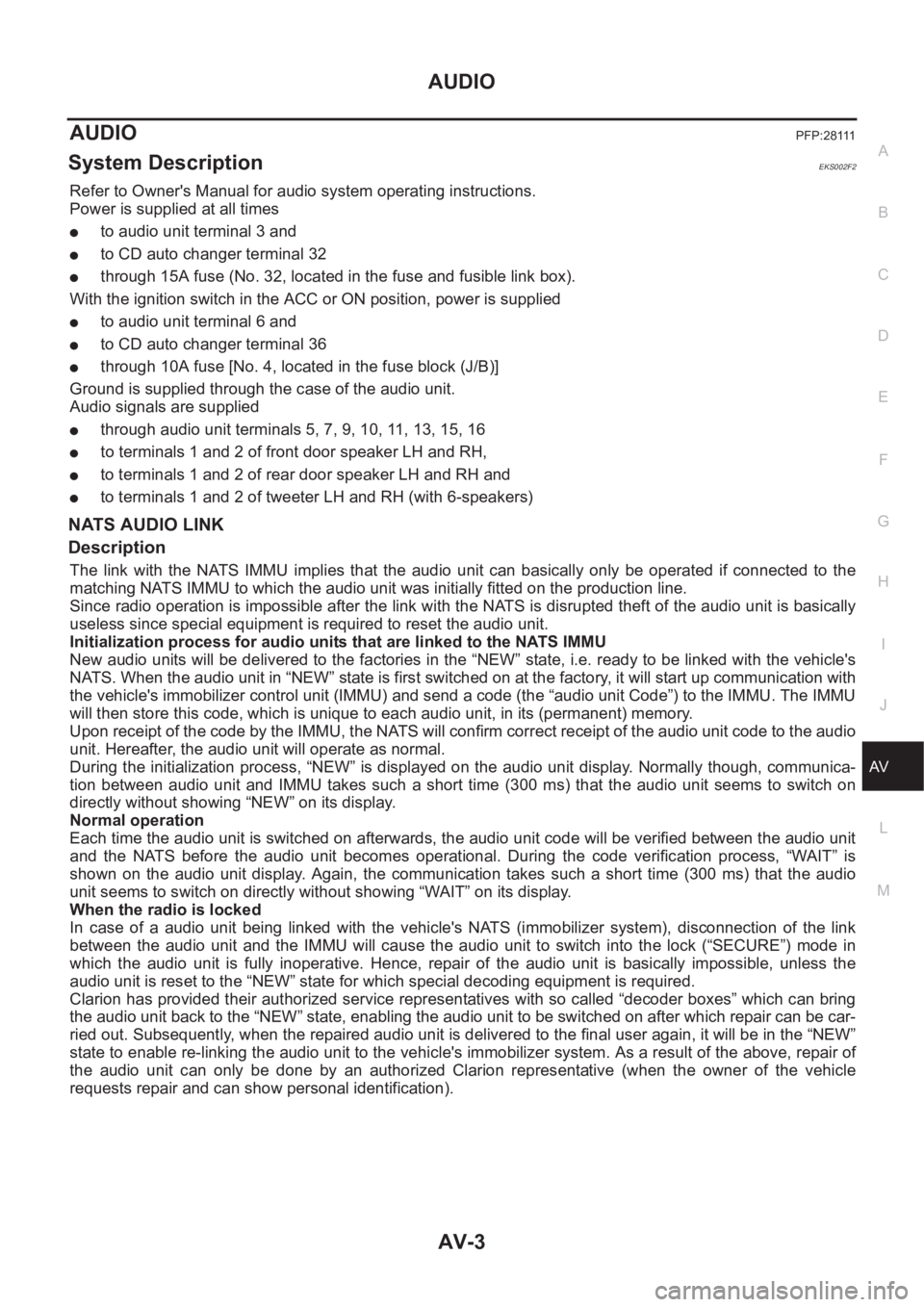
AUDIOPFP:28111
System DescriptionEKS002F2
Refer to Owner's Manual for audio system operating instructions.
Power is supplied at all times
●to audio unit terminal 3 and
●to CD auto changer terminal 32
●through 15A fuse (No. 32, located in the fuse and fusible link box).
With the ignition switch in the ACC or ON position, power is supplied
●to audio unit terminal 6 and
●to CD auto changer terminal 36
●through 10A fuse [No. 4, located in the fuse block (J/B)]
Ground is supplied through the case of the audio unit.
Audio signals are supplied
●through audio unit terminals 5, 7, 9, 10, 11, 13, 15, 16
●to terminals 1 and 2 of front door speaker LH and RH,
●to terminals 1 and 2 of rear door speaker LH and RH and
●to terminals 1 and 2 of tweeter LH and RH (with 6-speakers)
NATS AUDIO LINK
Description
The link with the NATS IMMU implies that the audio unit can basically only be operated if connected to the
matching NATS IMMU to which the audio unit was initially fitted on the production line.
Since radio operation is impossible after the link with the NATS is disrupted theft of the audio unit is basically
useless since special equipment is required to reset the audio unit.
Initialization process for audio units that are linked to the NAT S I M M U
New audio units will be delivered to the factories in the “NEW” state, i.e. ready to be linked with the vehicle's
NATS. When the audio unit in “NEW” state is first switched on at the factory, it will start up communication with
the vehicle's immobilizer control unit (IMMU) and send a code (the “audio unit Code”) to the IMMU. The IMMU
will then store this code, which is unique to each audio unit, in its (permanent) memory.
Upon receipt of the code by the IMMU, the NATS will confirm correct receipt of the audio unit code to the audio
unit. Hereafter, the audio unit will operate as normal.
During the initialization process, “NEW” is displayed on the audio unit display. Normally though, communica-
tion between audio unit and IMMU takes such a short time (300 ms) that the audio unit seems to switch on
directly without showing “NEW” on its display.
Normal operation
Each time the audio unit is switched on afterwards, the audio unit code will be verified between the audio unit
and the NATS before the audio unit becomes operational. During the code verification process, “WAIT” is
shown on the audio unit display. Again, the communication takes such a short time (300 ms) that the audio
unit seems to switch on directly without showing “WAIT” on its display.
When the radio is locked
In case of a audio unit being linked with the vehicle's NATS (immobilizer system), disconnection of the link
between the audio unit and the IMMU will cause the audio unit to switch into the lock (“SECURE”) mode in
which the audio unit is fully inoperative. Hence, repair of the audio unit is basically impossible, unless the
audio unit is reset to the “NEW” state for which special decoding equipment is required.
Clarion has provided their authorized service representatives with so called “decoder boxes” which can bring
the audio unit back to the “NEW” state, enabling the audio unit to be switched on after which repair can be car-
ried out. Subsequently, when the repaired audio unit is delivered to the final user again, it will be in the “NEW”
state to enable re-linking the audio unit to the vehicle's immobilizer system. As a result of the above, repair of
the audio unit can only be done by an authorized Clarion representative (when the owner of the vehicle
requests repair and can show personal identification).
Page 3692 of 3833

AV-4
AUDIO
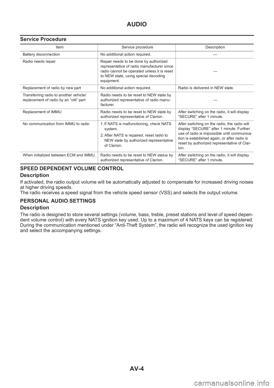
Service Procedure
SPEED DEPENDENT VOLUME CONTROL
Description
If activated, the radio output volume will be automatically adjusted to compensate for increased driving noises
at higher driving speeds.
The radio receives a speed signal from the vehicle speed sensor (VSS) and selects the output volume.
PERSONAL AUDIO SETTINGS
Description
The radio is designed to store several settings (volume, bass, treble, preset stations and level of speed depen-
dent volume control) with every NATS ignition key used. Up to a maximum of 4 NATS keys can be registered.
During the communication mentioned under “Anti-Theft System”, the radio will recognize the used ignition key
and select the accompanying settings.
Item Service procedure Description
Battery disconnection No additional action required. —
Radio needs repair Repair needs to be done by authorized
representative of radio manufacturer since
radio cannot be operated unless it is reset
to NEW state, using special decoding
equipment.—
Replacement of radio by new part No additional action required. Radio is delivered in NEW state.
Transferring radio to another vehicle/
replacement of radio by an “old” partRadio needs to be reset to NEW state by
authorized representative of radio manu-
facturer.—
Replacement of IMMU Radio needs to be reset to NEW state by
authorized representative of Clarion.After switching on the radio, it will display
“SECURE” after 1 minute.
No communication from IMMU to radio 1. If NATS is malfunctioning, check NATS
system.
2. After NATS is repaired, reset radio to
NEW state by authorized representative
of Clarion.After switching on the radio, the radio will
display “SECURE” after 1 minute. Further
use of radio is impossible until communica-
tion is established again, or after radio is
reset by authorized representative of Clar-
ion.
When initialized between ECM and IMMU. Radio needs to be reset to NEW status by
authorized representative of Clarion.After switching on the radio, it will display
“SECURE” after 1 minute.
Page 3765 of 3833

HARNESS
PG-61
C
D
E
F
G
H
I
J
L
MA
B
PG
FUEL EC Fuel Injection System Function
GLOW EC Glow Control System
H/AIM LT Headlamp Aiming Control System
H/LAMP LT Headlamp
H/SEAT SE Heated Seat
HEATER MTC Heater System
HLC WW Headlamp Cleaner
HO2S1 EC Heated Oxygen Sensor 1 (Front)
HO2S1H EC Heated Oxygen Sensor 1 Heater (Front)
HO2S2 EC Heated Oxygen Sensor 2 (Rear)
HO2S2H EC Heated Oxygen Sensor 2 Heater (Rear)
HORN WW Horn
IATS EC Intake Air Temperature Sensor
IATSEN EC Intake Air Temperature Sensor
IGN/SG EC Ignition Signal
IGNSYS EC Ignition Signal
ILL LT Illumination
INJECT EC Injector
INT/L LT Map Lamp
IVC EC Intake Valve Timing Control Solenoid Valve
IVC/V EC Intake Valve Timing Control Solenoid Valve
KS EC Knock Sensor (KS)
LOAD EC Electrical Load Signal
LPSV AT Line Pressure Solenoid Valve
MAFS EC Mass Air Flow Sensor (MAFS)
MAIN EC, AT Main Power Supply and Ground Circuit
METER DI Meter and Gauge
MIL EC Malfunction Indicator Lamp
MIL/DL EC MIL and Data Link Connector
MIRROR GW Door Mirror
MULTI BL Multi-Remote Control System
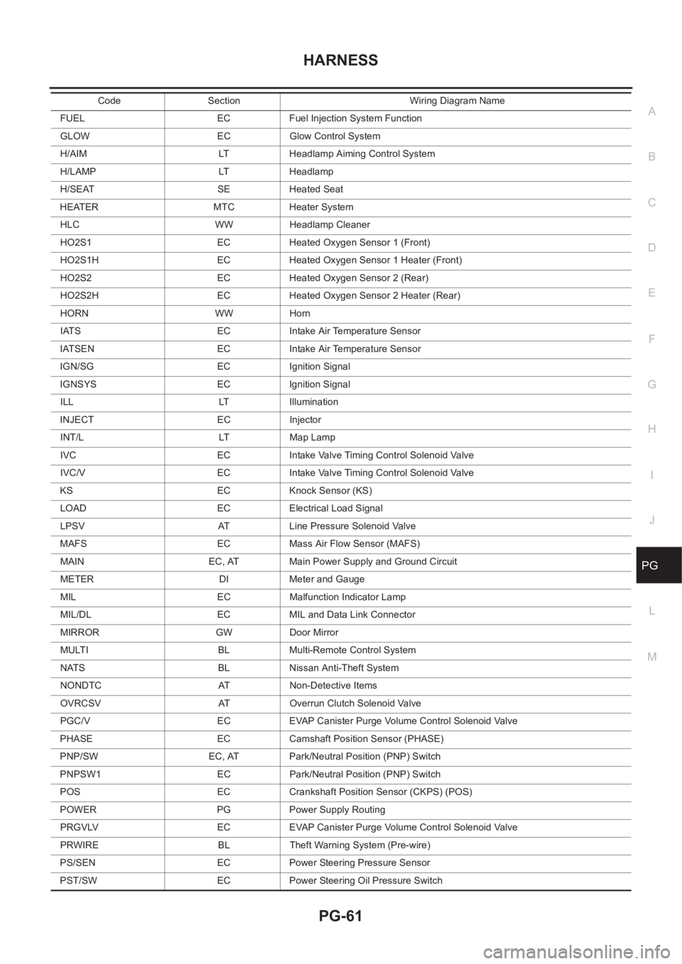
NATS BL Nissan Anti-Theft System
NONDTC AT Non-Detective Items
OVRCSV AT Overrun Clutch Solenoid Valve
PGC/V EC EVAP Canister Purge Volume Control Solenoid Valve
PHASE EC Camshaft Position Sensor (PHASE)
PNP/SW EC, AT Park/Neutral Position (PNP) Switch
PNPSW1 EC Park/Neutral Position (PNP) Switch
POS EC Crankshaft Position Sensor (CKPS) (POS)
POWER PG Power Supply Routing
PRGVLV EC EVAP Canister Purge Volume Control Solenoid Valve
PRWIRE BL Theft Warning System (Pre-wire)
PS/SEN EC Power Steering Pressure Sensor
PST/SW EC Power Steering Oil Pressure SwitchCode Section Wiring Diagram Name
Page 3831 of 3833

IDX-7
A
C
D
E
F
G
H
I
J
K
L B
IDX
ALPHABETICAL INDEX
Molding - See Exterior ................... EI-14,EI-16,EI-17
Mud guard - See Exterior .................................... EI-16
MULTI - Wiring diagram ..................................... BL-57
Multiport fuel injection (MFI) system ... EC-33,EC-443,
EC-765
,EC-1129
Multiport fuel injection precautions ....................... GI-6
Multi-remote control system ............................... BL-55
N
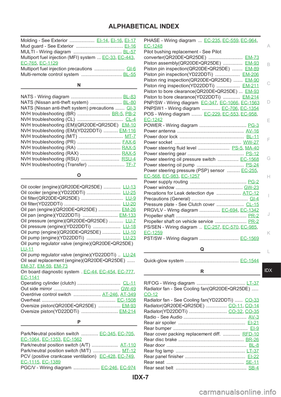
NATS - Wiring diagram ....................................... BL-83
NATS (Nissan anti-theft system) ........................ BL-80
NATS (Nissan anti-theft system) precautions ....... GI-3
NVH troubleshooting (BR) ......................... BR-5,PB-2
NVH troubleshooting (CL) ................................... CL-4
NVH troubleshooting (EM)(QR20DE•QR25DE) EM-10
NVH troubleshooting (EM)(YD22DDTi) ........... EM-116
NVH troubleshooting (M/T) .................................. MT-7
NVH troubleshooting (PR) ................................. FAX-6
NVH troubleshooting (RA) ................................. RAX-5
NVH troubleshooting (RAX) ............................... RAX-5
NVH troubleshooting (RSU) ............................. RSU-4
NVH troubleshooting (Transfer) ............................ TF-7
O
Oil cooler (engine)(QR20DE•QR25DE) ............. LU-13
Oil cooler (engine)(YD22DDTi) .......................... LU-25
Oil filter(QR20DE•QR25DE) ................................ LU-9
Oil filter(YD22DDTi) ........................................... LU-20
Oil pan (engine)(QR20DE•QR25DE) ................. EM-26
Oil pan (engine)(YD22DDTi) ........................... EM-133
Oil pressure (engine)(QR20DE•QR25DE) ........... LU-7
Oil pressure (engine)(YD22DDTi) ..................... LU-18
Oil pump (engine)(QR20DE•QR25DE) .............. LU-10
Oil pump (engine)(YD22DDTi) .......................... LU-23
Oil pump regulator valve (engine)(QR20DE•QR25DE)
LU-11
Oil pump regulator valve (engine)(YD22DDTi) .. LU-24
Oil seal replacement (engine)(QR20DE•QR25DE) ......
EM-37
,EM-59,EM-73
On board diagnostic system . EC-44,EC-454,EC-777,
EC-1141
Operating cylinder (clutch) ................................. CL-11
Out side mirror .................................................. GW-49
Overdrive control switch ..................... AT-246,AT-349
Overheat ........................................................ EC-1508
Oversize piston(QR20DE•QR25DE) ................. EM-93
Oversize piston(YD22DDTi) ............................ EM-214
P
Park/Neutral position switch ............. EC-345
,EC-705,
EC-1064
,EC-1353,EC-1562
Park/neutral position switch (A/T) .................... AT-110
Park/neutral position switch (M/T) ..................... MT-12
PCV (positive crankcase ventilation) EC-428,EC-749,
EC-1115
,EC-1389
PGC/V - Wiring diagram .................... EC-246,EC-974
PHASE - Wiring diagram ... EC-235,EC-559,EC-964,
EC-1248
Pilot bushing replacement - See Pilot
converter(QR20DE•QR25DE) .......................... EM-73
Piston assembly(QR20DE•QR25DE) ............... EM-93
Piston pin inspection(QR20DE•QR25DE) ........ EM-89
Piston pin inspection(YD22DDTi) ................... EM-206
Piston ring inspection(QR20DE•QR25DE) ....... EM-90
Piston ring inspection(YD22DDTi) .................. EM-211
Piston to bore clearance(QR20DE•QR25DE) ... EM-93
Piston to bore clearance(YD22DDTi) ............. EM-214
PNP/SW - Wiring diagram EC-347,EC-1066,EC-1563
PNPSW1 - Wiring diagram .............. EC-706,EC-1354
POS - Wiring diagram ........ EC-229,EC-553,EC-958,
EC-1242
POWER - Wiring diagram .................................... PG-3
Power antenna ................................................... AV-16
Power door lock ................................................. BL-11
Power socket ................................................... WW-27
Power steering fluid level ........................ PS-5,MA-40
Power steering gear ........................................... PS-12
Power steering oil pressure switch ................ EC-1568
Power steering oil pump .................................... PS-24
Power steering pressure (PSP) sensor .......... EC-255,
EC-568
,EC-983,EC-1257
Power supply routing ........................................... PG-2
Power window ................................................... GW-23
Precations for Leak detection dye ................... ATC-12
Precautions (General) ........................................... GI-4
Pressure plate - See Clutch cover ..................... CL-15
PRGVLV - Wirng diagram ................ EC-694,EC-1342
Propeller shaft ...................................................... PR-2
Propeller shaft on vehicle service ........................ PR-2
PS/SEN - Wiring diagram .. EC-257,EC-570,EC-985,
EC-1259
PST/SW - Wiring diagram .............................. EC-1569
Q
Quick-glow system ......................................... EC-1544
R
R/FOG - Wiring diagram ..................................... LT-37
Radiator fan - See Cooling fan(QR20DE•QR25DE) .....
CO-12
Radiator fan - See Cooling fan(YD22DDTi) ...... CO-33
Radiator(QR20DE•QR25DE) ................ CO-11,CO-14
Radiator(YD22DDTi) ............................. CO-32,CO-35
Radio - See Audio ................................................ AV-3
Rear air spoiler ................................................... EI-21
Rear bumper ......................................................... EI-9
Rear cover packing replacement diff. ............. RFD-10
Rear disc brake .................................................. BR-26
Rear door ............................................................. BL-8
Rear fog lamp ..................................................... LT-37
Rear panel finisher .............................................. EI-22
Rear seat ........................................................... SE-11
Rear seat belt ...................................................... SB-4