2001 NISSAN X-TRAIL air condition
[x] Cancel search: air conditionPage 1 of 3833

MODEL T30 SERIES
© 2002 NISSAN EUROPE S.A.S.
All rights reserved. No part of this Electronic Service Manual may be reproduced or stored in a retrieval system, or transmitted in any
form, or by any means, electronic, mechanical, photocopying, recording or otherwise, without the prior written permission of Nissan
Europe S.A.S., Paris, France.
A GENERAL INFORMATION
B ENGINE
C TRANSMISSION/
TRANSAXLE
D DRIVELINE/AXLE
E SUSPENSION
F BRAKES
G STEERING
H RESTRAINTS
IBODY
J AIR CONDITIONER
K ELECTRICAL
L MAINTENANCE
M INDEXGI General Information
EM Engine Mechanical
LU Engine Lubrication System
CO Engine Cooling System
EC Engine Control System
FL Fuel System
EX Exhaust System
ACC Accelerator Control System
CL Clutch
MT Manual Transaxle
AT Automatic Transaxle
TF Transfer
PR Propeller Shaft
RFD Rear Final Drive
FAX Front Axle
RAX Rear Axle
FSU Front Suspension
RSU Rear Suspension
WT Road Wheels & Tires
BR Brake System
PB Parking Brake System
BRC Brake Control System
PS Power Steering System
SB Seat Belts
SRS Supplemental Restraint System (SRS)
BL Body, Lock & Security System
GW Glasses, Window System & Mirrors
RF Roof
EI Exterior & Interior
IP Instrument Panel
SE Seat
ATC Automatic Air Conditioner
MTC Manual AIr Conditioner
SC Starting & Charging System
LT Lighting System
DI Driver Information System
WW Wiper, Washer & Horn
BCS Body Control System
LAN LAN System
AV Audio, Visual & Telephone System
PG Power Supply, Ground & Circuit Elements
MA Maintenance
IDX Alphabetical Index
QUICK REFERENCE INDEX
A
B
C
D
E
F
G
H
I
J
K
L
M
Page 3 of 3833

GI-1
GENERAL INFORMATION
A GENERAL INFORMATION
CONTENTS
C
D
E
F
G
H
I
J
K
L
MB
GI
SECTION
GENERAL INFORMATION
PRECAUTIONS .......................................................... 3
Description ............................................................... 3
Precautions for Supplemental Restraint System
(SRS) “AIR BAG” and “SEAT BELT PRE-TEN-
SIONER” .................................................................. 3
Precautions for NATS (NISSAN ANTI-THEFT SYS-
TEM) ........................................................................ 3
General Precautions ................................................ 4
Precautions for All Mode 4 × 4 System .................... 5
Precautions for Three Way Catalyst ......................... 5
Precautions for Fuel ................................................. 5
GASOLINE ENGINE ............................................. 5
DIESEL ENGINE ................................................... 5
Precautions for Multiport Fuel Injection System or
Engine Control System ............................................ 6
Precautions for Turbocharger (If Equipped) ............. 6
Precautions for Hoses .............................................. 6
HOSE REMOVAL AND INSTALLATION ............... 6
HOSE CLAMPING ................................................ 7
Precautions for Engine Oils ...................................... 7
HEALTH PROTECTION PRECAUTIONS ............. 7
ENVIRONMENTAL PROTECTION PRECAU-
TIONS ................................................................... 7
Precautions for Air Conditioning ............................... 7
HOW TO USE THIS MANUAL ................................... 8
Description ............................................................... 8
Terms ....................................................................... 8
Units ......................................................................... 8
Contents ................................................................... 8
Components ............................................................. 8
SYMBOLS ............................................................. 9
How to Follow Trouble Diagnoses ............................ 9
DESCRIPTION ...................................................... 9
HOW TO FOLLOW TEST GROUPS IN TROU-
BLE DIAGNOSES ............................................... 10
HARNESS WIRE COLOR AND CONNECTOR
NUMBER INDICATION ........................................ 11
KEY TO SYMBOLS SIGNIFYING MEASURE-
MENTS OR PROCEDURES ............................... 12
How to Read Wiring Diagrams ............................... 14CONNECTOR SYMBOLS ................................... 14
SAMPLE/WIRING DIAGRAM - EXAMPL - .......... 15
DESCRIPTION .................................................... 16
Abbreviations .......................................................... 22
SERVICE INFORMATION FOR ELECTRICAL INCI-
DENT ......................................................................... 23
How to Perform Efficient Diagnosis for an Electrical
Incident ................................................................... 23
WORK FLOW ...................................................... 23
INCIDENT SIMULATION TESTS ........................ 23
CIRCUIT INSPECTION ....................................... 26
Control Units and Electrical Parts ........................
... 31
PRECAUTIONS .................................................. 31
CONSULT-II CHECKING SYSTEM .......................... 33
Description .............................................................. 33
Function and System Application ........................... 33
Nickel Metal Hydride Battery Replacement ............ 33
Checking Equipment .............................................. 34
CONSULT-II Data Link Connector (DLC) Circuit .... 34
INSPECTION PROCEDURE .............................. 34
LIFTING POINT ......................................................... 35
Special Service Tools ............................................. 35
Garage Jack and Safety Stand ............................... 35
2-pole Lift ................................................................ 36
Board-on Lift ........................................................... 37
TOW TRUCK TOWING ............................................. 38
Tow Truck Towing ................................................... 38
TOWING AN AUTOMATIC TRANSAXLE
MODEL WITH FOUR WHEELS ON GROUND ... 38
T O W I N G T H E V E H I C L E W I T H R E A R W H E E L S
R A I S E D ( W I T H F R O N T W H E E L S O N G R O U N D )
OR FRONT WHEELS RAISED ........................... 39
Vehicle Recovery (Freeing a stuck vehicle) ............ 39
TIGHTENING TORQUE OF STANDARD BOLTS .... 40
Tightening Torque Table ......................................... 40
IDENTIFICATION INFORMATION ............................ 41
Model Variation ....................................................... 41
IDENTIFICATION NUMBER ................................ 42
IDENTIFICATION PLATE .................................... 43
ENGINE SERIAL NUMBER ................................ 43
Page 7 of 3833

PRECAUTIONS
GI-5
C
D
E
F
G
H
I
J
K
L
MB
GI
●Use approved bonding agent, sealants or their equivalents when required.
●Use tools and recommended special tools where specified for safe and efficient service repairs.
●When repairing the fuel, oil, water, vacuum or exhaust systems, check all affected lines for leaks.
●Before servicing the vehicle:
Protect fenders, upholstery and carpeting with appropriate cov-
ers.
Take caution that keys, buckles or buttons do not scratch paint.
WARNING:
To prevent ECM from storing the diagnostic trouble codes, do not carelessly disconnect the harness
connectors which are related to the engine control system and TCM (transmission control module)
system. The connectors should be disconnected only when working according to the WORK FLOW of
TROUBLE DIAGNOSES in EC and AT sections.
Precautions for All Mode 4 × 4 SystemEAS000GQ
Even if the 2WD mode is selected, the All mode 4 × 4 system occasionally changes from 2WD to 4WD auto-
matically depending on the driving conditions.
When spinning the front wheels by running the engine with the front wheels jacked up or mounted on the free
rollers / or a chassis dynamometer, be careful because the vehicle may suddenly move due to the driving
force from the rear wheels.
To avoid personal injury and vehicle damage, use one of the following methods when working with the front
wheels drive force and spinning freely.
● Remove the propeller shaft.
● Use free rollers / chassis dynamometer designed for 4WD vehicles.
Precautions for Three Way CatalystEAS000FR
If a large amount of unburned fuel flows into the catalyst, the catalyst temperature will be excessively high. To
prevent this, follow the instructions.
●Use unleaded gasoline only. Leaded gasoline will seriously damage the three way catalyst.
●When checking for ignition spark or measuring engine compression, make tests quickly and only when
necessary.
●Do not run engine when the fuel tank level is low, otherwise the engine may misfire, causing damage to
the catalyst.
Do not place the vehicle on flammable material. Keep flammable material off the exhaust pipe and the three
way catalyst.
Precautions for FuelEAS000P9
GASOLINE ENGINE
Use unleaded gasoline with an octane rating of at least 95 (RON).
CAUTION:
Do not use leaded gasoline. Using leaded gasoline will damage the three way catalyst. Using a fuel
other than that specified could adversely affect the emission control devices and systems, and could
also affect the warranty coverage validity.
DIESEL ENGINE
Diesel fuel of at least 50 cetane.
If two types of diesel fuel are available, use summer or winter fuel properly according to the following temper-
ature conditions.
●Above –7°C (20°F) ... Summer type diesel fuel.
●Below –7°C (20°F) ... Winter type diesel fuel.
SGI234
Page 9 of 3833
PRECAUTIONS
GI-7
C
D
E
F
G
H
I
J
K
L
MB
GI
HOSE CLAMPING
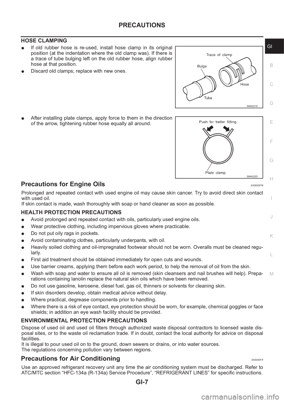
●If old rubber hose is re-used, install hose clamp in its original
position (at the indentation where the old clamp was). If there is
a trace of tube bulging left on the old rubber hose, align rubber
hose at that position.
●Discard old clamps; replace with new ones.
●After installing plate clamps, apply force to them in the direction
of the arrow, tightening rubber hose equally all around.
Precautions for Engine OilsEAS000FW
Prolonged and repeated contact with used engine oil may cause skin cancer. Try to avoid direct skin contact
with used oil.
If skin contact is made, wash thoroughly with soap or hand cleaner as soon as possible.
HEALTH PROTECTION PRECAUTIONS
●Avoid prolonged and repeated contact with oils, particularly used engine oils.
●Wear protective clothing, including impervious gloves where practicable.
●Do not put oily rags in pockets.
●Avoid contaminating clothes, particularly underpants, with oil.
●Heavily soiled clothing and oil-impregnated footwear should not be worn. Overalls must be cleaned regu-
larly.
●First aid treatment should be obtained immediately for open cuts and wounds.
●Use barrier creams, applying them before each work period, to help the removal of oil from the skin.
●Wash with soap and water to ensure all oil is removed (skin cleansers and nail brushes will help). Prepa-
rations containing lanolin replace the natural skin oils which have been removed.
●Do not use gasoline, kerosene, diesel fuel, gas oil, thinners or solvents for cleaning skin.
●If skin disorders develop, obtain medical advice without delay.
●Where practical, degrease components prior to handling.
●Where there is a risk of eye contact, eye protection should be worn, for example, chemical goggles or face
shields; in addition an eye wash facility should be provided.
ENVIRONMENTAL PROTECTION PRECAUTIONS
Dispose of used oil and used oil filters through authorized waste disposal contractors to licensed waste dis-
posal sites, or to the waste oil reclamation trade. If in doubt, contact the local authority for advice on disposal
facilities.
It is illegal to pour used oil on to the ground, down sewers or drains, or into water sources.
The regulations concerning pollution vary between regions.
Precautions for Air Conditioning EAS000FX
Use an approved refrigerant recovery unit any time the air conditioning system must be discharged. Refer to
ATC/MTC section “HFC-134a (R-134a) Service Procedure”, “REFRIGERANT LINES” for specific instructions.
SMA021D
SMA022D
Page 24 of 3833
GI-22
HOW TO USE THIS MANUAL
Abbreviations
EAS000G5
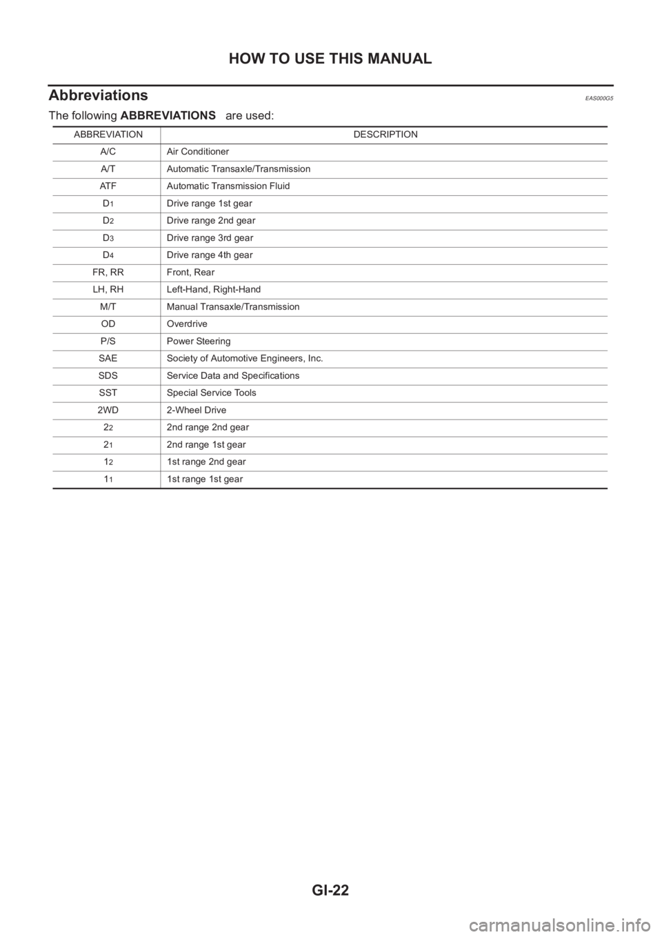
The following ABBREVIATIONS are used:
ABBREVIATION DESCRIPTION
A/C Air Conditioner
A/T Automatic Transaxle/Transmission
ATF Automatic Transmission Fluid
D
1Drive range 1st gear
D
2Drive range 2nd gear
D
3Drive range 3rd gear
D
4Drive range 4th gear
FR, RR Front, Rear
LH, RH Left-Hand, Right-Hand
M/T Manual Transaxle/Transmission
OD Overdrive
P/S Power Steering
SAE Society of Automotive Engineers, Inc.
SDS Service Data and Specifications
SST Special Service Tools
2WD 2-Wheel Drive
2
22nd range 2nd gear
2
12nd range 1st gear
1
21st range 2nd gear
1
11st range 1st gear
Page 25 of 3833
SERVICE INFORMATION FOR ELECTRICAL INCIDENT
GI-23
C
D
E
F
G
H
I
J
K
L
MB
GI
SERVICE INFORMATION FOR ELECTRICAL INCIDENTPFP:00000
How to Perform Efficient Diagnosis for an Electrical IncidentEAS000G6
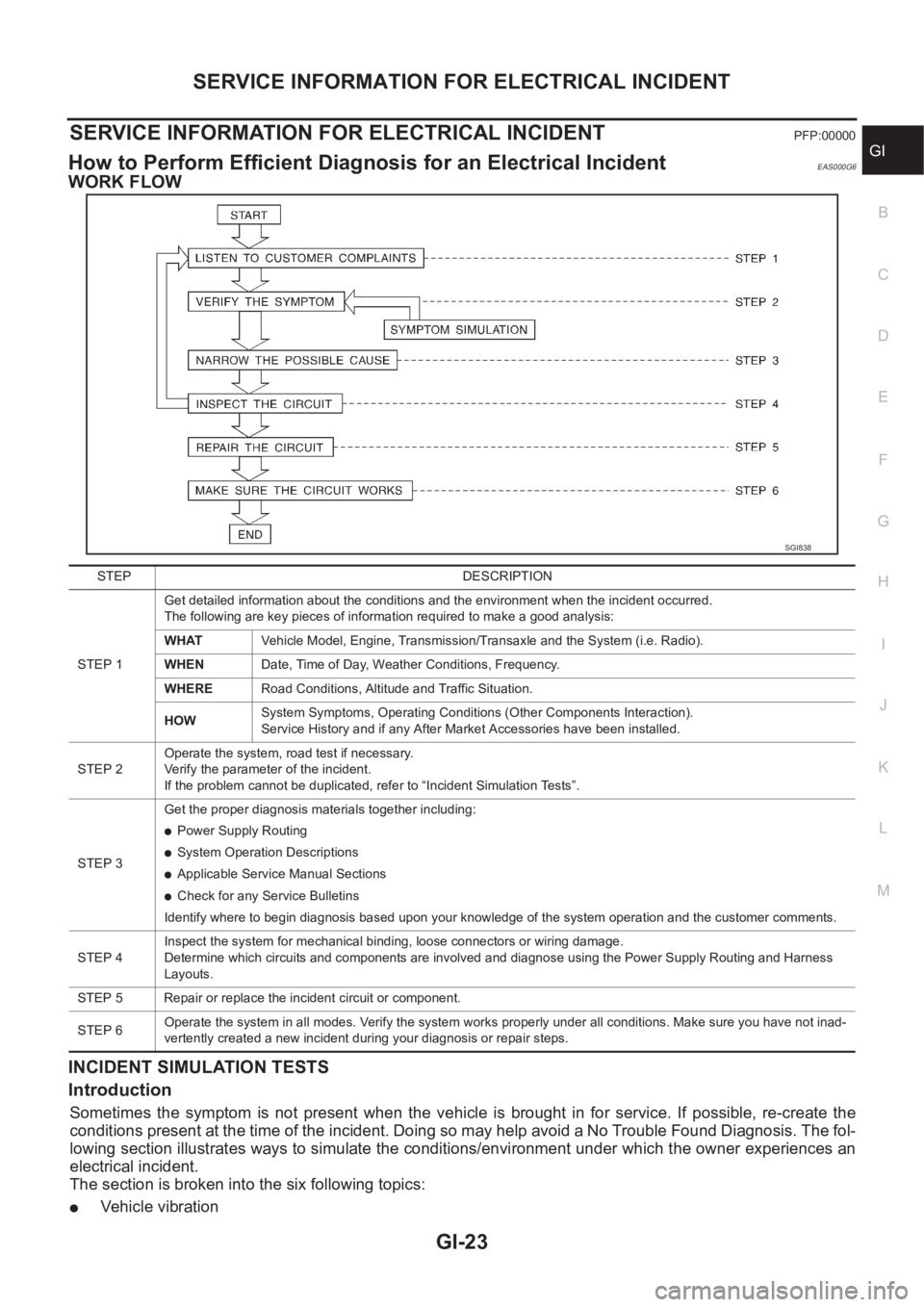
WORK FLOW
INCIDENT SIMULATION TESTS
Introduction
Sometimes the symptom is not present when the vehicle is brought in for service. If possible, re-create the
conditions present at the time of the incident. Doing so may help avoid a No Trouble Found Diagnosis. The fol-
lowing section illustrates ways to simulate the conditions/environment under which the owner experiences an
electrical incident.
The section is broken into the six following topics:
●Vehicle vibration
SGI838
STEP DESCRIPTION
STEP 1Get detailed information about the conditions and the environment when the incident occurred.
The following are key pieces of information required to make a good analysis:
WHATVehicle Model, Engine, Transmission/Transaxle and the System (i.e. Radio).
WHENDate, Time of Day, Weather Conditions, Frequency.
WHERERoad Conditions, Altitude and Traffic Situation.
HOWSystem Symptoms, Operating Conditions (Other Components Interaction).
Service History and if any After Market Accessories have been installed.
STEP 2Operate the system, road test if necessary.
Verify the parameter of the incident.
If the problem cannot be duplicated, refer to “Incident Simulation Tests”.
STEP 3Get the proper diagnosis materials together including:
●Power Supply Routing
●System Operation Descriptions
●Applicable Service Manual Sections
●Check for any Service Bulletins
Identify where to begin diagnosis based upon your knowledge of the system operation and the customer comments.
STEP 4Inspect the system for mechanical binding, loose connectors or wiring damage.
Determine which circuits and components are involved and diagnose using the Power Supply Routing and Harness
Layouts.
STEP 5 Repair or replace the incident circuit or component.
STEP 6Operate the system in all modes. Verify the system works properly under all conditions. Make sure you have not inad-
vertently created a new incident during your diagnosis or repair steps.
Page 27 of 3833
SERVICE INFORMATION FOR ELECTRICAL INCIDENT
GI-25
C
D
E
F
G
H
I
J
K
L
MB
GI
UNDER SEATING AREAS
An unclamped or loose harness can cause wiring to be pinched by seat components (such as slide guides)
during vehicle vibration. If the wiring runs under seating areas, inspect wire routing for possible damage or
pinching.
Heat Sensitive
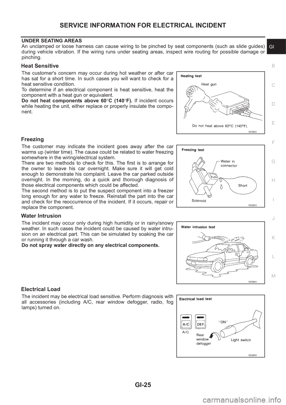
The customer's concern may occur during hot weather or after car
has sat for a short time. In such cases you will want to check for a
heat sensitive condition.
To determine if an electrical component is heat sensitive, heat the
component with a heat gun or equivalent.
Do not heat components above 60°C (140°F). If incident occurs
while heating the unit, either replace or properly insulate the compo-
nent.
Freezing
The customer may indicate the incident goes away after the car
warms up (winter time). The cause could be related to water freezing
somewhere in the wiring/electrical system.
There are two methods to check for this. The first is to arrange for
the owner to leave his car overnight. Make sure it will get cold
enough to demonstrate his complaint. Leave the car parked outside
overnight. In the morning, do a quick and thorough diagnosis of
those electrical components which could be affected.
The second method is to put the suspect component into a freezer
long enough for any water to freeze. Reinstall the part into the car
and check for the reoccurrence of the incident. If it occurs, repair or
replace the component.
Water Intrusion
The incident may occur only during high humidity or in rainy/snowy
weather. In such cases the incident could be caused by water intru-
sion on an electrical part. This can be simulated by soaking the car
or running it through a car wash.
Do not spray water directly on any electrical components.
Electrical Load
The incident may be electrical load sensitive. Perform diagnosis with
all accessories (including A/C, rear window defogger, radio, fog
lamps) turned on.
SGI842
SGI843
SGI844
SGI845
Page 35 of 3833
CONSULT-II CHECKING SYSTEM
GI-33
C
D
E
F
G
H
I
J
K
L
MB
GI
CONSULT-II CHECKING SYSTEMPFP:00000
DescriptionEAS000G8
●CONSULT-II is a hand-held type tester. When it is connected with a diagnostic connector equipped on the
vehicle side, it will communicate with the control unit equipped in the vehicle and then enable various
kinds of diagnostic tests.
●Refer to “CONSULT-II Software Operation Manual” for more information.
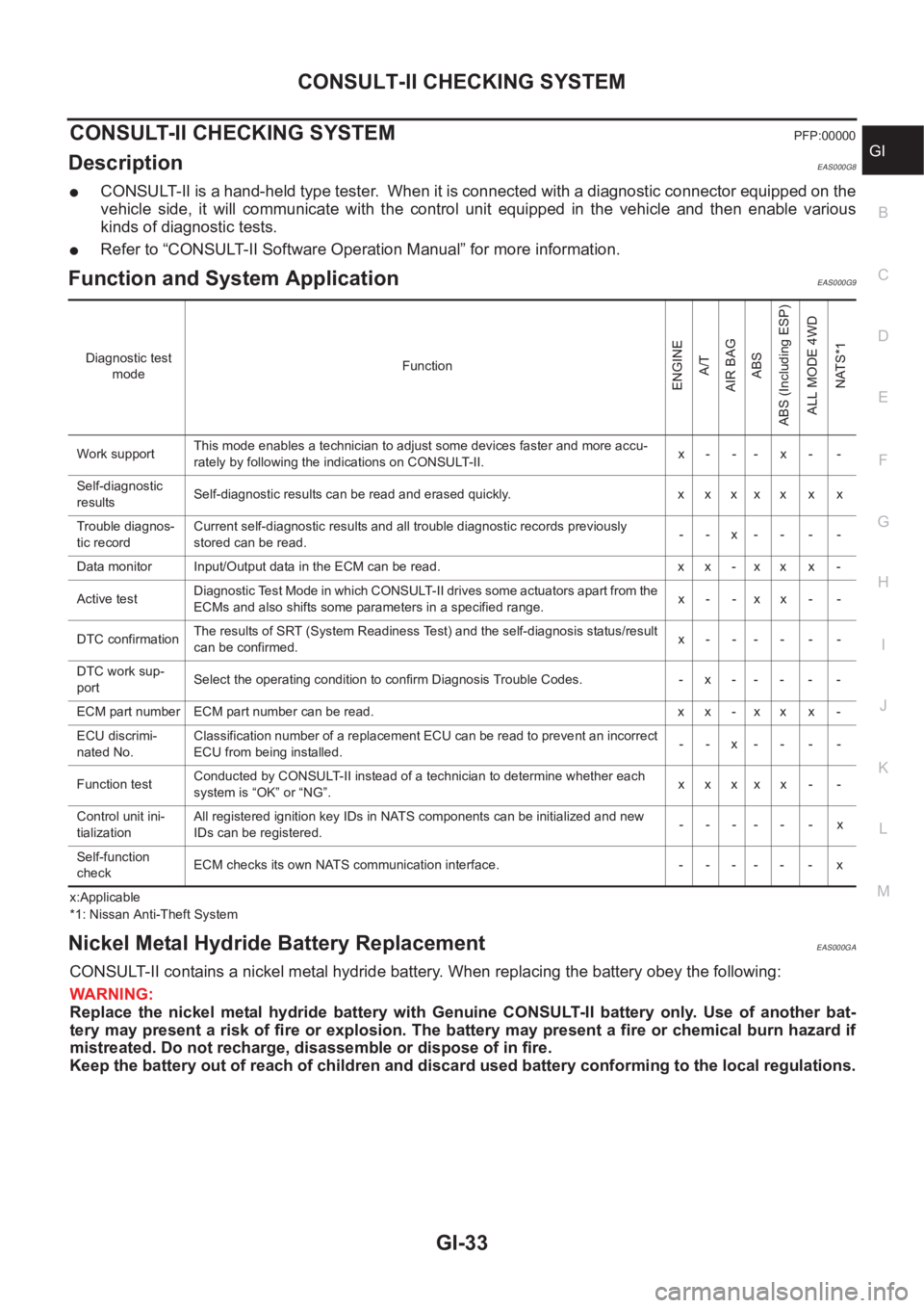
Function and System Application EAS000G9
x:Applicable
*1: Nissan Anti-Theft System
Nickel Metal Hydride Battery Replacement EAS000GA
CONSULT-II contains a nickel metal hydride battery. When replacing the battery obey the following:
WARNING:
Replace the nickel metal hydride battery with Genuine CONSULT-II battery only. Use of another bat-
tery may present a risk of fire or explosion. The battery may present a fire or chemical burn hazard if
mistreated. Do not recharge, disassemble or dispose of in fire.
Keep the battery out of reach of children and discard used battery conforming to the local regulations.
Diagnostic test
modeFunction
ENGINE
A/T
AIR BAG
ABS
ABS (Including ESP)
ALL MODE 4WD
NATS*1
Work supportThis mode enables a technician to adjust some devices faster and more accu-
rately by following the indications on CONSULT-II.x- -- x- -
Self-diagnostic
resultsSelf-diagnostic results can be read and erased quickly. x x x x x x x
Trouble diagnos-
tic recordCurrent self-diagnostic results and all trouble diagnostic records previously
stored can be read.--x----
Data monitor Input/Output data in the ECM can be read. x x - x x x -
Active testDiagnostic Test Mode in which CONSULT-II drives some actuators apart from the
ECMs and also shifts some parameters in a specified range.x- -xx- -
DTC confirmationThe results of SRT (System Readiness Test) and the self-diagnosis status/result
can be confirmed.x------
DTC work sup-
portSelect the operating condition to confirm Diagnosis Trouble Codes. -x-----
ECM part number ECM part number can be read. x x - x x x -
ECU discrimi-
nated No.Classification number of a replacement ECU can be read to prevent an incorrect
ECU from being installed.--x----
Function testConducted by CONSULT-II instead of a technician to determine whether each
system is “OK” or “NG”.xxxxx - -
Control unit ini-
tializationAll registered ignition key IDs in NATS components can be initialized and new
IDs can be registered.------x
Self-function
checkECM checks its own NATS communication interface. - - - - - - x