2001 NISSAN X-TRAIL Crank yd22
[x] Cancel search: Crank yd22Page 52 of 3833
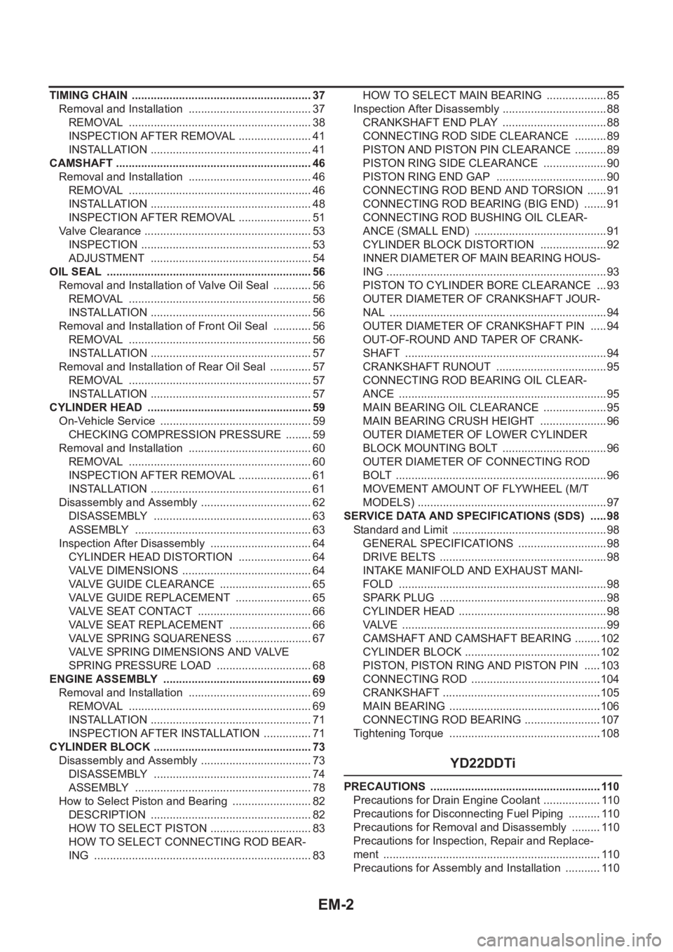
EM-2
TIMING CHAIN .......................................................... 37
Removal and Installation ........................................ 37
REMOVAL ........................................................... 38
INSPECTION AFTER REMOVAL ........................ 41
INSTALLATION .................................................... 41
CAMSHAFT ............................................................... 46
Removal and Installation ........................................ 46
REMOVAL ........................................................... 46
INSTALLATION .................................................... 48
INSPECTION AFTER REMOVAL ........................ 51
Valve Clearance ...................................................... 53
INSPECTION ....................................................... 53
ADJUSTMENT .................................................... 54
OIL SEAL .................................................................. 56
Removal and Installation of Valve Oil Seal ............. 56
REMOVAL ........................................................... 56
INSTALLATION .................................................... 56
Removal and Installation of Front Oil Seal ............. 56
REMOVAL ........................................................... 56
INSTALLATION .................................................... 57
Removal and Installation of Rear Oil Seal .............. 57
REMOVAL ........................................................... 57
INSTALLATION .................................................... 57
CYLINDER HEAD .................................................. ... 59
On-Vehicle Service ................................................. 59
CHECKING COMPRESSION PRESSURE ......... 59
Removal and Installation ........................................ 60
REMOVAL ........................................................... 60
INSPECTION AFTER REMOVAL ........................ 61
INSTALLATION .................................................... 61
Disassembly and Assembly .................................... 62
DISASSEMBLY ................................................... 63
ASSEMBLY ......................................................... 63
Inspection After Disassembly ................................. 64
CYLINDER HEAD DISTORTION ........................ 64
VALVE DIMENSIONS .......................................... 64
VALVE GUIDE CLEARANCE .............................. 65
VALVE GUIDE REPLACEMENT ......................... 65
VALVE SEAT CONTACT ..................................... 66
VALVE SEAT REPLACEMENT ........................... 66
VALVE SPRING SQUARENESS ......................... 67
VALVE SPRING DIMENSIONS AND VALVE
SPRING PRESSURE LOAD ............................... 68
ENGINE ASSEMBLY ................................................ 69
Removal and Installation ........................................ 69
REMOVAL .......................................................
.... 69
INSTALLATION .................................................... 71
INSPECTION AFTER INSTALLATION ................ 71
CYLINDER BLOCK ................................................... 73
Disassembly and Assembly .................................... 73
DISASSEMBLY ................................................... 74
ASSEMBLY ......................................................... 78
How to Select Piston and Bearing .......................... 82
DESCRIPTION .................................................... 82
HOW TO SELECT PISTON ................................. 83
HOW TO SELECT CONNECTING ROD BEAR-
ING ...................................................................... 83HOW TO SELECT MAIN BEARING .................... 85
Inspection After Disassembly .................................. 88
CRANKSHAFT END PLAY .................................. 88
CONNECTING ROD SIDE CLEARANCE ........... 89
PISTON AND PISTON PIN CLEARANCE ........... 89
PISTON RING SIDE CLEARANCE ..................... 90
PISTON RING END GAP .................................... 90
CONNECTING ROD BEND AND TORSION ....... 91
CONNECTING ROD BEARING (BIG END) ........ 91
CONNECTING ROD BUSHING OIL CLEAR-
ANCE (SMALL END) ........................................... 91
CYLINDER BLOCK DISTORTION ...................... 92
INNER DIAMETER OF MAIN BEARING HOUS-
ING ....................................................................... 93
PISTON TO CYLINDER BORE CLEARANCE .... 93
OUTER DIAMETER OF CRANKSHAFT JOUR-
NAL ...................................................................... 94
OUTER DIAMETER OF CRANKSHAFT PIN ...... 94
OUT-OF-ROUND AND TAPER OF CRANK-
SHAFT ................................................................. 94
CRANKSHAFT RUNOUT .................................... 95
CONNECTING ROD BEARING OIL CLEAR-
ANCE ................................................................... 95
MAIN BEARING OIL CLEARANCE ..................... 95
MAIN BEARING CRUSH HEIGHT ...................... 96
OUTER DIAMETER OF LOWER CYLINDER
BLOCK MOUNTING BOLT .................................. 96
OUTER DIAMETER OF CONNECTING ROD
BOLT .................................................................... 96
MOVEMENT AMOUNT OF FLYWHEEL (M/T
MODELS) ............................................................. 97
SERVICE DATA AND SPECIFICATIONS (SDS) ...... 98
Standard and Limit .................................................. 98
GENERAL SPECIFICATIONS ............................. 98
DRIVE BELTS ...................................................... 98
INTAKE MANIFOLD AND EXHAUST MANI-
FOLD ................................................................... 98
SPARK PLUG ...................................................... 98
CYLINDER HEAD ................................................ 98
VALVE .................................................................. 99
CAMSHAFT AND CAMSHAFT BEARING .........102
CYLINDER BLOCK ............................................102
PISTON, PISTON RING AND PISTON PIN .....
.103
CONNECTING ROD ..........................................104
CRANKSHAFT ...................................................105
MAIN BEARING .................................................106
CONNECTING ROD BEARING .........................107
Tightening Torque .................................................108
YD22DDTi
PRECAUTIONS .......................................................110
Precautions for Drain Engine Coolant ...................110
Precautions for Disconnecting Fuel Piping ...........110
Precautions for Removal and Disassembly ..........110
Precautions for Inspection, Repair and Replace-
ment ......................................................................110
Precautions for Assembly and Installation ............110
Page 160 of 3833
![NISSAN X-TRAIL 2001 Service Repair Manual EM-110
[YD22DDTi]
PRECAUTIONS
[YD22DDTi]PRECAUTIONSPFP:00001
Precautions for Drain Engine CoolantEBS00LQZ
Drain engine coolant when engine is cooled.
Precautions for Disconnecting Fuel PipingEBS00LR0](/manual-img/5/57405/w960_57405-159.png "NISSAN X-TRAIL 2001 Service Repair Manual EM-110
[YD22DDTi]
PRECAUTIONS
[YD22DDTi]PRECAUTIONSPFP:00001
Precautions for Drain Engine CoolantEBS00LQZ
Drain engine coolant when engine is cooled.
Precautions for Disconnecting Fuel PipingEBS00LR0")
EM-110
[YD22DDTi]
PRECAUTIONS
[YD22DDTi]PRECAUTIONSPFP:00001
Precautions for Drain Engine CoolantEBS00LQZ
Drain engine coolant when engine is cooled.
Precautions for Disconnecting Fuel PipingEBS00LR0
●Before starting work, make sure no fire or spark producing items are in the work area.
●Release fuel pressure before disassembly.
●After disconnecting pipes, plug openings to stop fuel leakage.
Precautions for Removal and DisassemblyEBS00LR1
●When instructed to use special service tools, use the specified tools. Always be careful to work safely,
avoid forceful or uninstructed operations.
●Exercise maximum care to avoid damage to mating or sliding surfaces.
●Cover openings of engine system with tape or the equivalent, if necessary, to seal out foreign materials.
●Mark and arrange disassembly parts in an organized way for easy troubleshooting and re-assembly.
●When loosening nuts and bolts, as a basic rule, start with the one furthest outside, then the one diagonally
opposite, and so on. If the order of loosening is specified, do exactly as specified.
Precautions for Inspection, Repair and ReplacementEBS00LR2
Before repairing or replacing, thoroughly inspect parts. Inspect new replacement parts in the same way, and
replace if necessary.
Precautions for Assembly and InstallationEBS00LR3
●Use torque wrench to tighten bolts or nuts to specification.
●When tightening nuts and bolts, as a basic rule, equally tighten in several different steps starting with the
ones in center, then ones on inside and outside diagonally in this order. If the order of tightening is speci-
fied, do exactly as specified.
●Replace with new liquid gasket, packing, oil seal or O-ring.
●Thoroughly wash, clean, and air-blow each part. Carefully check engine oil or engine coolant passages for
any restriction and blockage.
●Avoid damaging sliding or mating surfaces. Completely remove foreign materials such as cloth lint or dust.
Before assembly, engine oil sliding surfaces well.
●Release air within route when refilling after draining coolant.
●After repairing, start engine and increase engine speed to check engine coolant, fuel, engine oil, and
exhaust systems for leakage.
Parts Requiring Angular TighteningEBS00LR4
●Use an angle wrench for the final tightening of the following engine parts:
–Cylinder head bolts
–Main bearing cap bolts
–Connecting rod cap nuts
–Crankshaft pulley bolt (No angle wrench is required as the bolt flange is provided with notches for angular
tightening)
●Do not use a torque value for final tightening.
●The torque value for these parts are for a preliminary step.
●Ensure thread and seat surfaces are clean and coated with engine oil.
Page 162 of 3833
![NISSAN X-TRAIL 2001 Service Repair Manual EM-112
[YD22DDTi]
PREPARATION
PREPARATION
PFP:00002
Special Service ToolsEBS00LR6
Tool number
Tool nameDescription
ST0501S000
Engine stand assembly
1. ST05011000
Engine stand
2. ST05012000
BaseDisasse](/manual-img/5/57405/w960_57405-161.png "NISSAN X-TRAIL 2001 Service Repair Manual EM-112
[YD22DDTi]
PREPARATION
PREPARATION
PFP:00002
Special Service ToolsEBS00LR6
Tool number
Tool nameDescription
ST0501S000
Engine stand assembly
1. ST05011000
Engine stand
2. ST05012000
BaseDisasse")
EM-112
[YD22DDTi]
PREPARATION
PREPARATION
PFP:00002
Special Service ToolsEBS00LR6
Tool number
Tool nameDescription
ST0501S000
Engine stand assembly
1. ST05011000
Engine stand
2. ST05012000
BaseDisassembling and assembling
KV10106500
Engine stand shaft
KV11105900
Engine sub-attachmentUsed with KV10106500
KV10115600
Valve oil seal driftInstalling valve oil seal
Use side A.
Side A
a: 20 (0.79) dia.
b: 13 (0.51) dia.
c: 10.3 (0.406) dia.
d: 8 (0.31) dia.
e: 10.7 (0.421)
f: 5 (0.20)
Unit: mm (in)
KV10107902
Valve oil seal puller
1. KV10116100
Valve oil seal puller adapterRemoving valve oil seal
KV11103000
Injection pump drive gear pullerRemoving crankshaft pulley
NT042
NT028
NT799
NT603
S-NT605
NT676
Page 163 of 3833
![NISSAN X-TRAIL 2001 Service Repair Manual PREPARATION
EM-113
[YD22DDTi]
C
D
E
F
G
H
I
J
K
L
MA
EM
KV101056S0
Ring gear stopper
1. KV10105630
Adapter
2. KV10105610
PlatePreventing crankshaft from rotating
a: 3 (0.12)
b: 6.4 (0.252)
c: 2.8 (0.1](/manual-img/5/57405/w960_57405-162.png "NISSAN X-TRAIL 2001 Service Repair Manual PREPARATION
EM-113
[YD22DDTi]
C
D
E
F
G
H
I
J
K
L
MA
EM
KV101056S0
Ring gear stopper
1. KV10105630
Adapter
2. KV10105610
PlatePreventing crankshaft from rotating
a: 3 (0.12)
b: 6.4 (0.252)
c: 2.8 (0.1")
PREPARATION
EM-113
[YD22DDTi]
C
D
E
F
G
H
I
J
K
L
MA
EM
KV101056S0
Ring gear stopper
1. KV10105630
Adapter
2. KV10105610
PlatePreventing crankshaft from rotating
a: 3 (0.12)
b: 6.4 (0.252)
c: 2.8 (0.110)
d: 6.6 (0.260)
e: 107 (4.21)
f: 14 (0.55)
g: 20 (0.79)
h: 14 (0.55) dia.
Unit: mm (in)
KV101151S0
Lifter stopper set
1. KV10115110
Camshaft pliers
2. KV10115120
Lifter stopperChanging valve lifter shims
ST16610001
Pilot bushing pullerRemoving crankshaft pilot bushing
K V 1 0 1111 0 0
Seal cutterRemoving steel oil pan and rear timing chain
case
WS39930000
Tube presserPressing the tube of liquid gasket
KV10112100
Angle wrenchTightening bolts for bearing cap, cylinder
head, etc.
EM03470000
Piston ring compressorInstalling piston assembly into cylinder bore Tool number
To o l n a m eDescription
NT617
NT041
NT045
NT046
NT052
NT014
NT044
Page 167 of 3833
![NISSAN X-TRAIL 2001 Service Repair Manual NOISE, VIBRATION, AND HARSHNESS (NVH) TROUBLESHOOTING
EM-117
[YD22DDTi]
C
D
E
F
G
H
I
J
K
L
MA
EM
Use the Chart Below to Help You Find the Cause of the Symptom.EBS00LR9
1. Locate the area where noise](/manual-img/5/57405/w960_57405-166.png "NISSAN X-TRAIL 2001 Service Repair Manual NOISE, VIBRATION, AND HARSHNESS (NVH) TROUBLESHOOTING
EM-117
[YD22DDTi]
C
D
E
F
G
H
I
J
K
L
MA
EM
Use the Chart Below to Help You Find the Cause of the Symptom.EBS00LR9
1. Locate the area where noise")
NOISE, VIBRATION, AND HARSHNESS (NVH) TROUBLESHOOTING
EM-117
[YD22DDTi]
C
D
E
F
G
H
I
J
K
L
MA
EM
Use the Chart Below to Help You Find the Cause of the Symptom.EBS00LR9
1. Locate the area where noise occurs.
2. Confirm the type of noise.
3. Specify the operating condition of engine.
4. Check specified noise source.
If necessary, repair or replace these parts.
A: Closely related B: Related C: Sometimes related —: Not relatedLocation
of noiseType of
noiseOperating condition of engine
Source of
noiseCheck itemRefer-
ence page Before
warm-
upAfter
warm-
upWhen
start-
ingWhen
idlingWhen
racingWhile
driving
Top of
engine
Rocker
cover
Cylinder
headTicking or
clickingCA—AB—Tappet
noiseValve clearanceEM-163
Rattle C A — A B CCamshaft
bearing
noiseCamshaft oil clearance
Camshaft runoutEM-160EM-159
Crank-
shaft pul-
ley
Cylinder
block
(Side of
engine)
Oil panSlap or
knock—A—BB—Piston pin
noisePiston to piston pin
clearance
Connecting rod bush-
ing oil clearance (Small
end)EM-210
EM-212
Slap or
rapA ——BBAPiston
slap noisePiston to cylinder bore
clearance
Piston ring side clear-
ance
Piston ring end gap
Connecting rod bend
and torsionEM-214EM-211
EM-211
EM-212
Knock A B C B B BConnect-
ing rod
bearing
noiseConnecting rod bush-
ing oil clearance (Small
end)
Connecting rod bear-
ing oil clearance (Big
end)EM-212EM-216
Knock A B — A B CMain
bearing
noiseMain bearing oil clear-
ance
Crankshaft runoutEM-216EM-216
Front of
engine
Timing
chain
coverTapping or
tickingA A —BBBTiming
chain and
chain ten-
sioner
noiseTiming chain cracks
and wear
Timing chain tensioner
operationEM-167
EM-172
Front of
engineSqueak-
ing or fizz-
ingAB—B—CDrive belts
(Sticking
or slip-
ping)Drive belts deflection
EM-118
CreakingA B ABABDrive belts
(Slipping)Idler pulley bearing
operation
Squall
CreakA B —BABWater
pump
noiseWater pump operationCO-39,
"WATER
PUMP"
Page 168 of 3833
![NISSAN X-TRAIL 2001 Service Repair Manual EM-118
[YD22DDTi]
DRIVE BELTS
DRIVE BELTS
PFP:02117
Checking Drive BeltsEBS00LRA
●Before inspecting the engine, make sure the engine has cooled
down; wait approximately 30 minutes after the engine h](/manual-img/5/57405/w960_57405-167.png "NISSAN X-TRAIL 2001 Service Repair Manual EM-118
[YD22DDTi]
DRIVE BELTS
DRIVE BELTS
PFP:02117
Checking Drive BeltsEBS00LRA
●Before inspecting the engine, make sure the engine has cooled
down; wait approximately 30 minutes after the engine h")
EM-118
[YD22DDTi]
DRIVE BELTS
DRIVE BELTS
PFP:02117
Checking Drive BeltsEBS00LRA
●Before inspecting the engine, make sure the engine has cooled
down; wait approximately 30 minutes after the engine has been
stopped.
●Visually inspect all belts for wear, damage or cracks on contact-
ing surfaces and edge areas.
●When measuring deflection, apply 98 N (10 kg, 22 lb) at the
marked point ( ).
CAUTION:
●When checking belt deflection immediately after installa-
tion, first adjust it to the specified value. Then, after turn-
ing the crankshaft two turns or more, re-adjust to the
specified value to avoid variation in deflection between
pulleys.
●Tighten idler pulley lock nut by hand and measure deflection without looseness.
Belt Deflection:
*: When engine is cold.
Tension AdjustmentEBS00LRB
●Adjust belts with the parts shown below.
CAUTION:
●When a new belt is installed as a replacement, adjust it to the value specified under “New” value
because of insufficient adaptability with pulley grooves.
●If the belt deflection of the current belt is out of the “Limit for re-adjusting”, adjust to the
“Adjusted” value.
●When checking belt deflection immediately after installation, first adjust it to the specified value.
Then, after turning crankshaft two turns or more, re-adjust it to the specified value to avoid vari-
ation in deflection between pulleys.
●Make sure the belts are fully fitted into the pulley grooves during installation.
●Handle with care to avoid smearing the belts with engine oil or cooling water etc.
●Do not twist or bend the belts with strong force.
JEM249G
Applied beltBelt deflection with 98 N (10 kg, 22 lb) force applied* mm (in)
New Adjusted Limit for re-adjusting
Air conditioner compressor belt 4 - 5 (0.16 - 0.20) 6 - 7 (0.24 - 0.28) 8.5 (0.335)
Alternator and water pump belt 9.0 - 10.5 (0.354 - 0.413) 11.0 - 12.5 (0.433 - 0.492) 16.5 (0.650)
Applied belt Belt adjustment method
Air conditioner compressor belt Adjusting bolt on idler pulley
Alternator and water pump belt Adjusting bolt on alternator
Page 183 of 3833
![NISSAN X-TRAIL 2001 Service Repair Manual OIL PAN AND OIL STRAINER
EM-133
[YD22DDTi]
C
D
E
F
G
H
I
J
K
L
MA
EM
OIL PAN AND OIL STRAINERP F P : 1111 0
Removal and InstallationEBS00LRK
REMOVAL
WARNING:
To avoid the danger of being scalded, neve](/manual-img/5/57405/w960_57405-182.png "NISSAN X-TRAIL 2001 Service Repair Manual OIL PAN AND OIL STRAINER
EM-133
[YD22DDTi]
C
D
E
F
G
H
I
J
K
L
MA
EM
OIL PAN AND OIL STRAINERP F P : 1111 0
Removal and InstallationEBS00LRK
REMOVAL
WARNING:
To avoid the danger of being scalded, neve")
OIL PAN AND OIL STRAINER
EM-133
[YD22DDTi]
C
D
E
F
G
H
I
J
K
L
MA
EM
OIL PAN AND OIL STRAINERP F P : 1111 0
Removal and InstallationEBS00LRK
REMOVAL
WARNING:
To avoid the danger of being scalded, never drain the engine oil when the engine is hot.
1. Remove engine undercover at both side.
2. Drain engine oil. Refer to LU-19, "
Changing Engine Oil" .
3. Remove lower oil pan bolts, Loosen bolts in the reverse order of
that shown in the figure.
PBIC1140E
1. Rear plate cover 2. Oil pan upper 3. Oil strainer
4. Drain plug 5. Oil pan lower 6 Crankshaft position sensor (TDC)
SBIA0161E
Page 184 of 3833
![NISSAN X-TRAIL 2001 Service Repair Manual EM-134
[YD22DDTi]
OIL PAN AND OIL STRAINER
4. Remove lower oil pan.
a. Insert Tool (seal cutter) between upper oil pan and lower oil pan.
●Be careful not to damage aluminum mating surface.
●Do no](/manual-img/5/57405/w960_57405-183.png "NISSAN X-TRAIL 2001 Service Repair Manual EM-134
[YD22DDTi]
OIL PAN AND OIL STRAINER
4. Remove lower oil pan.
a. Insert Tool (seal cutter) between upper oil pan and lower oil pan.
●Be careful not to damage aluminum mating surface.
●Do no")
EM-134
[YD22DDTi]
OIL PAN AND OIL STRAINER
4. Remove lower oil pan.
a. Insert Tool (seal cutter) between upper oil pan and lower oil pan.
●Be careful not to damage aluminum mating surface.
●Do not insert screwdriver, or oil pan flange will be
deformed.
b. Slide Tool by tapping on the side of the Tool with a hammer.
c. Remove lower oil pan.
5. Remove drive belts.
6. Remove A/C compressor and bracket.
7. Remove front exhaust tube and its support.
8. Set a suitable transmission jack under transaxle and hoist
engine with engine slinger. Refer to EM-193, "
Removal and
Installation" .
9. Remove center member.
10. Remove crankshaft position sensor (TDC) from transaxle.
CAUTION:
●Avoid impacts such as a dropping.
●Do not disassemble.
●Keep it away from metal particles.
●Do not place sensor close to magnetic materials.
11. Remove rear plate cover and four engine-to transaxle bolts.
12. Remove catalyst and rear diffuser. Refer to EM-126, "
Removal
and Installation" .
SEM544G
SEM545G
JEM553G
PBIB0416E