2001 NISSAN X-TRAIL tires
[x] Cancel search: tiresPage 1 of 3833

MODEL T30 SERIES
© 2002 NISSAN EUROPE S.A.S.
All rights reserved. No part of this Electronic Service Manual may be reproduced or stored in a retrieval system, or transmitted in any
form, or by any means, electronic, mechanical, photocopying, recording or otherwise, without the prior written permission of Nissan
Europe S.A.S., Paris, France.
A GENERAL INFORMATION
B ENGINE
C TRANSMISSION/
TRANSAXLE
D DRIVELINE/AXLE
E SUSPENSION
F BRAKES
G STEERING
H RESTRAINTS
IBODY
J AIR CONDITIONER
K ELECTRICAL
L MAINTENANCE
M INDEXGI General Information
EM Engine Mechanical
LU Engine Lubrication System
CO Engine Cooling System
EC Engine Control System
FL Fuel System
EX Exhaust System
ACC Accelerator Control System
CL Clutch
MT Manual Transaxle
AT Automatic Transaxle
TF Transfer
PR Propeller Shaft
RFD Rear Final Drive
FAX Front Axle
RAX Rear Axle
FSU Front Suspension
RSU Rear Suspension
WT Road Wheels & Tires
BR Brake System
PB Parking Brake System
BRC Brake Control System
PS Power Steering System
SB Seat Belts
SRS Supplemental Restraint System (SRS)
BL Body, Lock & Security System
GW Glasses, Window System & Mirrors
RF Roof
EI Exterior & Interior
IP Instrument Panel
SE Seat
ATC Automatic Air Conditioner
MTC Manual AIr Conditioner
SC Starting & Charging System
LT Lighting System
DI Driver Information System
WW Wiper, Washer & Horn
BCS Body Control System
LAN LAN System
AV Audio, Visual & Telephone System
PG Power Supply, Ground & Circuit Elements
MA Maintenance
IDX Alphabetical Index
QUICK REFERENCE INDEX
A
B
C
D
E
F
G
H
I
J
K
L
M
Page 41 of 3833
TOW TRUCK TOWING
GI-39
C
D
E
F
G
H
I
J
K
L
MB
GI
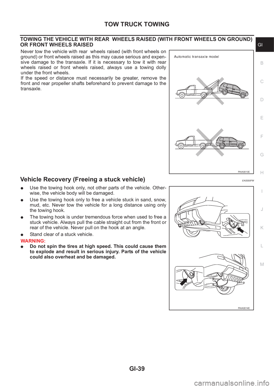
TOWING THE VEHICLE WITH REAR WHEELS RAISED (WITH FRONT WHEELS ON GROUND)
OR FRONT WHEELS RAISED
Never tow the vehicle with rear wheels raised (with front wheels on
ground) or front wheels raised as this may cause serious and expen-
sive damage to the transaxle. If it is necessary to tow it with rear
wheels raised or front wheels raised, always use a towing dolly
under the front wheels.
If the speed or distance must necessarily be greater, remove the
front and rear propeller shafts beforehand to prevent damage to the
transaxle.
Vehicle Recovery (Freeing a stuck vehicle) EAS000FM
●Use the towing hook only, not other parts of the vehicle. Other-
wise, the vehicle body will be damaged.
●Use the towing hook only to free a vehicle stuck in sand, snow,
mud, etc. Never tow the vehicle for a long distance using only
the towing hook.
●The towing hook is under tremendous force when used to free a
stuck vehicle. Always pull the cable straight out from the front or
rear of the vehicle. Never pull on the hook at an angle.
●Stand clear of a stuck vehicle.
WARNING:
●Do not spin the tires at high speed. This could cause them
to explode and result in serious injury. Parts of the vehicle
could also overheat and be damaged.
PAIA0013E
PAIA0014E
Page 46 of 3833
GI-44
IDENTIFICATION INFORMATION
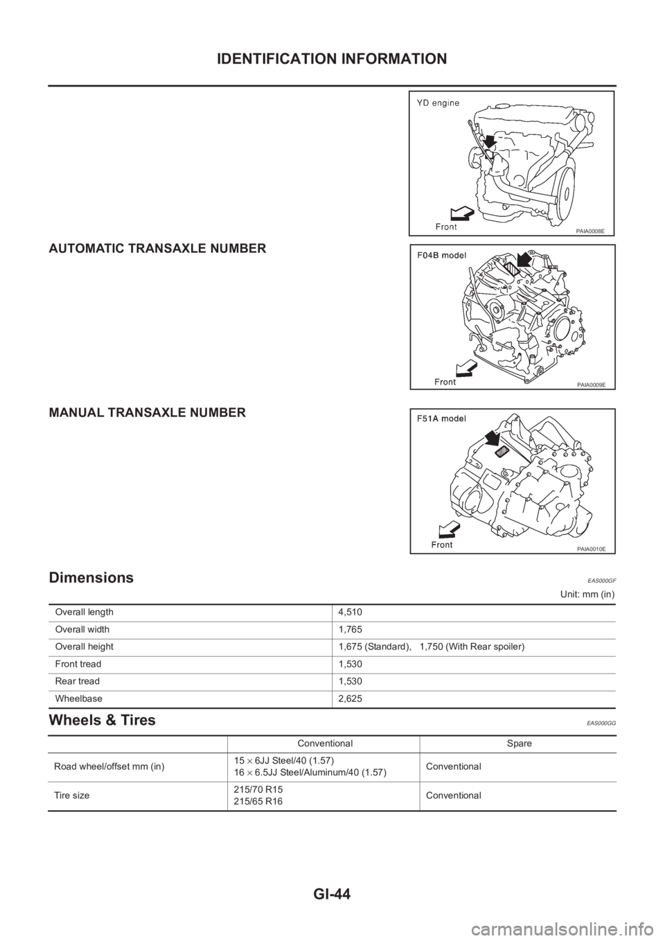
AUTOMATIC TRANSAXLE NUMBER
MANUAL TRANSAXLE NUMBER
Dimensions EAS000GF
Unit: mm (in)
Wheels & Tires EAS000GG
PAIA0008E
PAIA0009E
PAIA0010E
Overall length 4,510
Overall width 1,765
Overall height 1,675 (Standard), 1,750 (With Rear spoiler)
Front tread 1,530
Rear tread 1,530
Wheelbase 2,625
Conventional Spare
Road wheel/offset mm (in)15 × 6JJ Steel/40 (1.57)
16 × 6.5JJ Steel/Aluminum/40 (1.57)Conventional
Tir e s iz e215/70 R15
215/65 R16Conventional
Page 312 of 3833
![NISSAN X-TRAIL 2001 Service Repair Manual CO-6
[QR]
OVERHEATING CAUSE ANALYSIS
Except cool-
ing system
parts mal-
function— Overload on engineAbusive drivingHigh engine rpm under no
load
Driving in low gear for
extended time
Driving at e NISSAN X-TRAIL 2001 Service Repair Manual CO-6
[QR]
OVERHEATING CAUSE ANALYSIS
Except cool-
ing system
parts mal-
function— Overload on engineAbusive drivingHigh engine rpm under no
load
Driving in low gear for
extended time
Driving at e](/manual-img/5/57405/w960_57405-311.png)
CO-6
[QR]
OVERHEATING CAUSE ANALYSIS
Except cool-
ing system
parts mal-
function— Overload on engineAbusive drivingHigh engine rpm under no
load
Driving in low gear for
extended time
Driving at extremely high
speed
Powertrain system mal-
function
— Installed improper size
wheels and tires
Dragging brakes
Improper ignition timing
Blocked or restricted air
flowBlocked bumper —
— Blocked radiator grilleInstalled car brassiere
Mud contamination or
paper clogging
Blocked radiator —
Blocked condenser
Blocked air flow
Installed large fog lamp Symptom Check items
Page 332 of 3833
![NISSAN X-TRAIL 2001 Service Repair Manual CO-26
[YD22DDTi]
OVERHEATING CAUSE ANALYSIS
Except cool-
ing system
parts mal-
function— Overload on engineAbusive drivingHigh engine rpm under no
load
Driving in low gear for
extended time
Drivi NISSAN X-TRAIL 2001 Service Repair Manual CO-26
[YD22DDTi]
OVERHEATING CAUSE ANALYSIS
Except cool-
ing system
parts mal-
function— Overload on engineAbusive drivingHigh engine rpm under no
load
Driving in low gear for
extended time
Drivi](/manual-img/5/57405/w960_57405-331.png)
CO-26
[YD22DDTi]
OVERHEATING CAUSE ANALYSIS
Except cool-
ing system
parts mal-
function— Overload on engineAbusive drivingHigh engine rpm under no
load
Driving in low gear for
extended time
Driving at extremely high
speed
Powertrain system mal-
function
— Installed improper size
wheels and tires
Dragging brakes
Improper ignition timing
Blocked or restricted air
flowBlocked bumper —
— Blocked radiator grilleInstalled car brassiere
Mud contamination or
paper clogging
Blocked radiator —
Blocked condenser
Blocked air flow
Installed large fog lamp Symptom Check items
Page 2641 of 3833
ALL MODE 4X4 SYSTEM
TF-31
C
E
F
G
H
I
J
K
L
MA
B
TF
4WD MODE SWITCH
AUTO mode (AUTO indicator lamp ON)
●Electronic control allows optimal distribution of torque to front/rear wheels to match road conditions.
●Makes possible stable driving, with no wheel spin, on snowy roads or other slippery surfaces.
●On roads which do not require 4WD, it contributes to improved fuel economy by driving in conditions close
to front-wheel drive.
●Sensors determine the vehicle's turning condition, and in response tight cornering/braking are controlled
by distributing optimum torque to rear wheels.
NOTE:
●When driving in AUTO mode or LOCK mode, if there is a large difference between front and rear wheel
speed which continues for a long time, oil temperature of drive system parts becomes too high and 4WD
warning lamp flashes rapidly. (When 4WD warning lamp flashes, vehicle changes to front-wheel drive
conditions.)
● When driving in AUTO mode, 4WD warning lamp may flash slowly if there is a significant difference in
pressure or wear between tires. At this time, vehicle performance is not fully available and cautious driving
is required. (Continues until engine is turned OFF.)
●If 4WD warning lamp is flashing rapidly, stop vehicle and allow it to idle for some time. Flashing will stop
and AUTO mode will be restored.
●If the warning lamp flashes slowly during driving but remains OFF after engine is restarted, the system is
normal. If it again flashes slowly after driving for some time, vehicle must be inspected.
●When the difference of revolution speed between the front and rear wheel with AUTO mode the shift
switch occasionally changes to LOCK mode automatically. This is not malfunction.
LOCK mode (LOCK indicator lamp and AUTO indicator lamp ON)
●Front/rear wheel torque distribution is fixed, ensuring stable driving when climbing slopes.
●When LOCK mode is selected, vehicle will switch automatically to AUTO mode if vehicle speed increases.
If vehicle speed then decreases, the vehicle automatically returns to direct 4-wheel driving conditions.
NOTE:
If there is a significant difference in pressure or wear between tires, full vehicle performance is not available.
Tire conditions are detected, and LOCK mode may be prohibited, or else speeds at which LOCK mode is
enabled may be restricted.
2WD mode (indicator lamps OFF)
Vehicle is in front-wheel drive.
NOTE:
● If front wheels are slipping in 2WD mode, do not switch to AUTO or LOCK. This can cause difficulties for
the system.
● The shift switch even if the shift switch is in 2WD mode, the sift switch occasionally automatically change
to 4WD mode depending on the driving condition (For example; Depressing the acceleration firmly). this is
not malfunction. How ever, 4WD mode indicator lamp dose not illuminate.
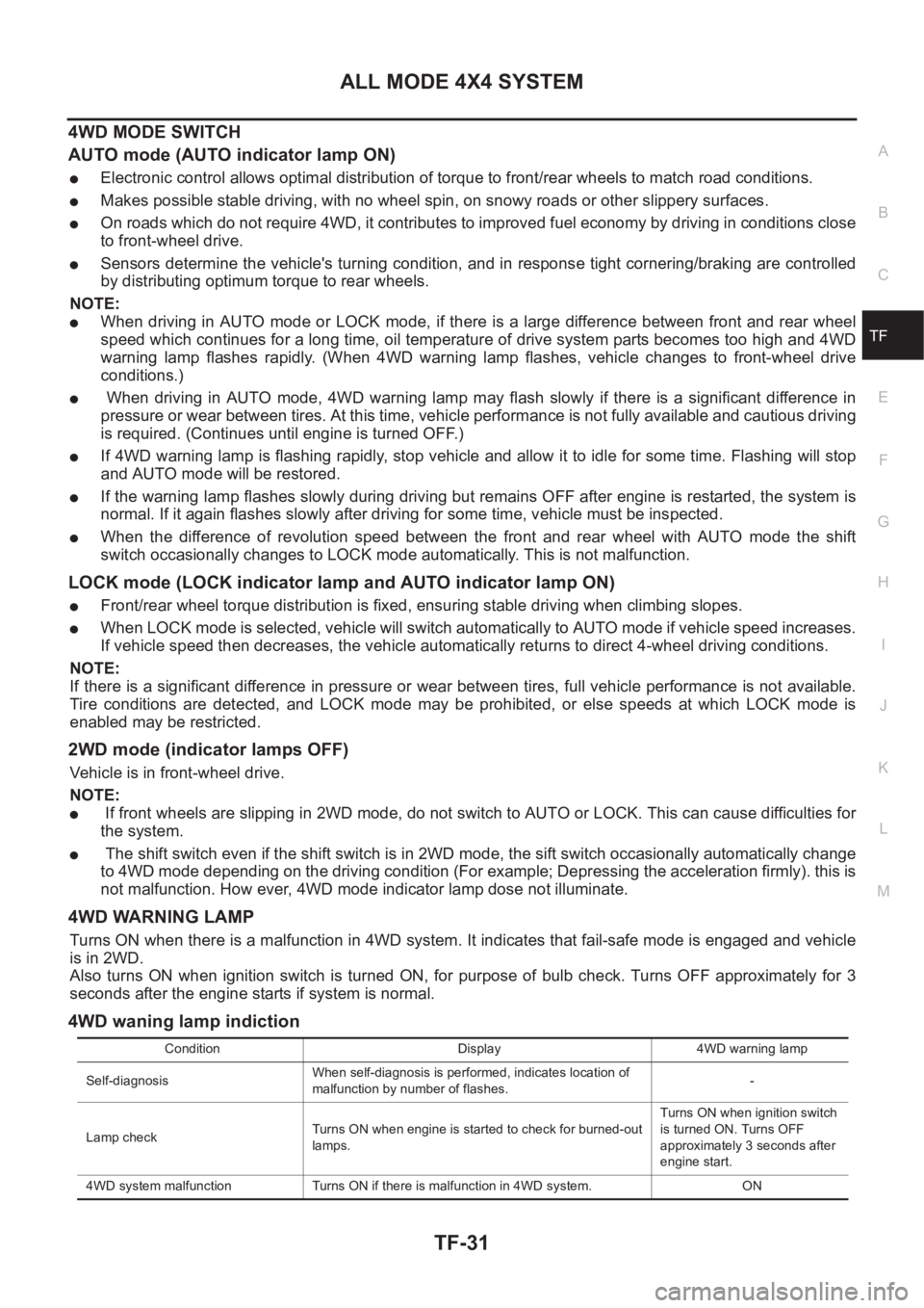
4WD WARNING LAMP
Turns ON when there is a malfunction in 4WD system. It indicates that fail-safe mode is engaged and vehicle
is in 2WD.
Also turns ON when ignition switch is turned ON, for purpose of bulb check. Turns OFF approximately for 3
seconds after the engine starts if system is normal.
4WD waning lamp indiction
Condition Display 4WD warning lamp
Self-diagnosisWhen self-diagnosis is performed, indicates location of
malfunction by number of flashes.-
Lamp checkTurns ON when engine is started to check for burned-out
lamps.Turns ON when ignition switch
is turned ON. Turns OFF
approximately 3 seconds after
engine start.
4WD system malfunction Turns ON if there is malfunction in 4WD system. ON
Page 2642 of 3833
TF-32
ALL MODE 4X4 SYSTEM
FAIL- SAFE FUNCTION
●If a malfunction occurs in 4WD electrical system, and control unit detects the malfunction, 4WD warning
lamp on gauge turns ON to inform driver of system malfunction.
●When 4WD warning lamp is ON, vehicle is in 2WD.
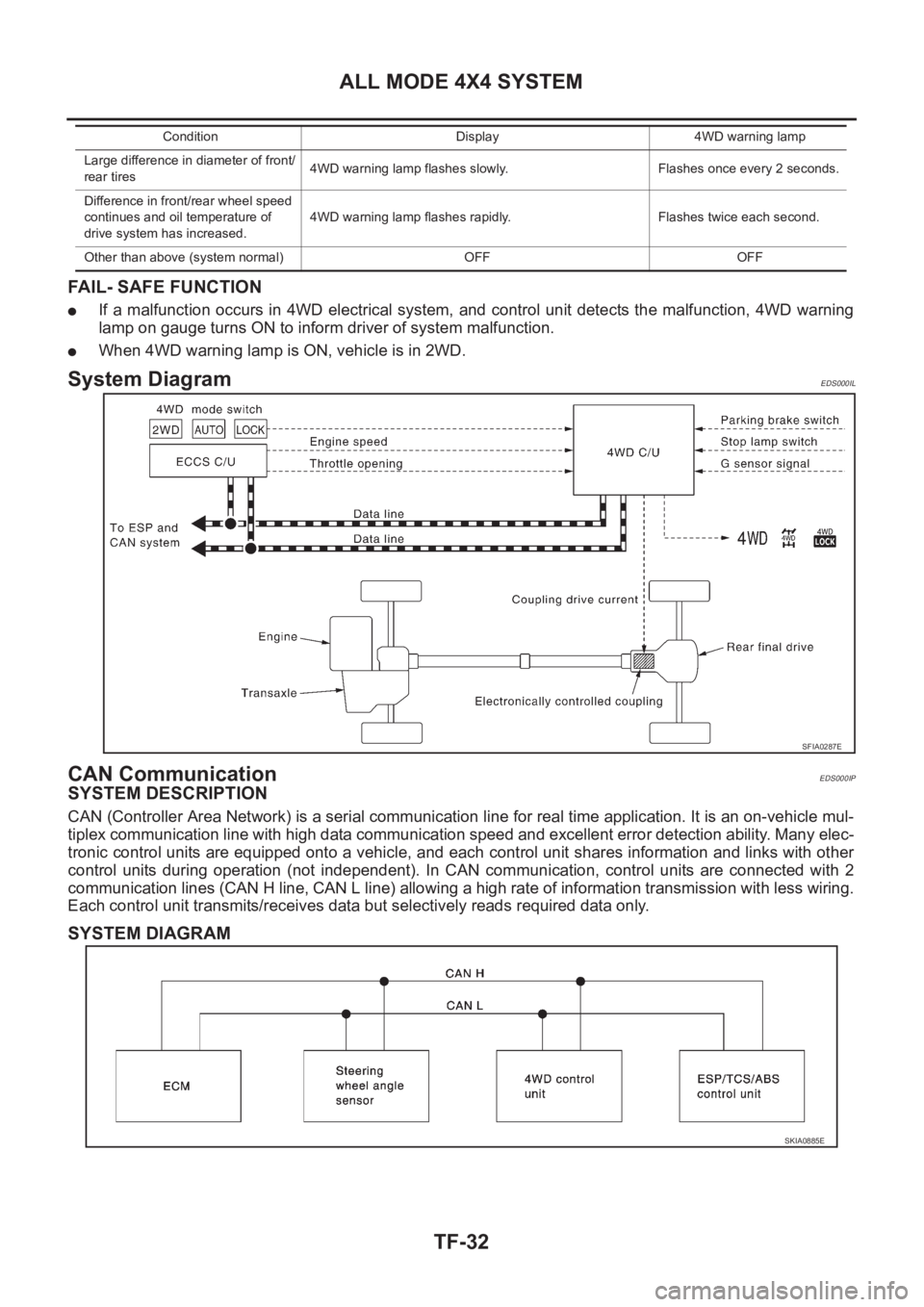
System DiagramEDS000IL
CAN CommunicationEDS000IP
SYSTEM DESCRIPTION
CAN (Controller Area Network) is a serial communication line for real time application. It is an on-vehicle mul-
tiplex communication line with high data communication speed and excellent error detection ability. Many elec-
tronic control units are equipped onto a vehicle, and each control unit shares information and links with other
control units during operation (not independent). In CAN communication, control units are connected with 2
communication lines (CAN H line, CAN L line) allowing a high rate of information transmission with less wiring.
Each control unit transmits/receives data but selectively reads required data only.
SYSTEM DIAGRAM
Large difference in diameter of front/
rear tires4WD warning lamp flashes slowly. Flashes once every 2 seconds.
Difference in front/rear wheel speed
continues and oil temperature of
drive system has increased.4WD warning lamp flashes rapidly. Flashes twice each second.
Other than above (system normal) OFF OFFCondition Display 4WD warning lamp
SFIA0287E
SKIA0885E
Page 2668 of 3833
TF-58
TROUBLE DIAGNOSIS
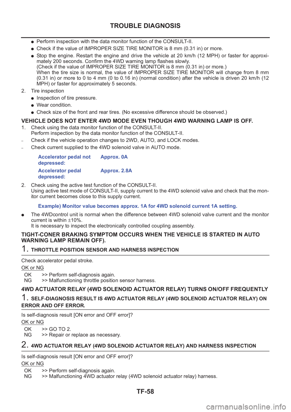
●Perform inspection with the data monitor function of the CONSULT- I I .
●Check if the value of IMPROPER SIZE TIRE MONITOR is 8 mm (0.31 in) or more.
●Stop the engine. Restart the engine and drive the vehicle at 20 km/h (12 MPH) or faster for approxi-
mately 200 seconds. Confirm the 4WD warning lamp flashes slowly.
(Check if the value of IMPROPER SIZE TIRE MONITOR is 8 mm (0.31 in) or more.)
When the tire size is normal, the value of IMPROPER SIZE TIRE MONITOR will change from 8 mm
(0.31 in) or more to 0 to 4 mm (0 to 0.16 in) (normal condition) after the vehicle is driven 20 km/h (12
MPH) or faster for approximately 5 seconds.
2. Tire inspection
●Inspection of tire pressure.
●Wear condition.
●Check size of the front and rear tires. (No excessive difference should be observed.)
VEHICLE DOES NOT ENTER 4WD MODE EVEN THOUGH 4WD WARNING LAMP IS OFF.
1. Check using the data monitor function of the CONSULT-II.
Perform inspection by the data monitor function of the CONSULT-II.
–Check if the vehicle operation changes to 2WD, AUTO, and LOCK modes.
–Check current supplied to the 4WD solenoid valve in AUTO mode.
2. Check using the active test function of the CONSULT-II.
Using active test mode of CONSULT-II, supply current to the 4WD solenoid valve and check that the mon-
itor current becomes close to this supply current.
●The 4WDcontrol unit is normal when the difference between 4WD solenoid valve current and the monitor
current is within ±10%.
It is necessary to inspect the electronically controlled coupling assembly.
TIGHT-CONER BRAKING SYMPTOM OCCURS WHEN THE VEHICLE IS STARTED IN AUTO
WARNING LAMP REMAIN OFF).
1. THROTTLE POSITION SENSOR AND HARNESS INSPECTION
Check accelerator pedal stroke.
OK or NG
OK >> Perform self-diagnosis again.
NG >> Malfunctioning throttle position sensor harness.
4WD ACTUATOR RELAY (4WD SOLENOID ACTUATOR RELAY) TURNS ON/OFF FREQUENTLY
1. SELF-DIAGNOSIS RESULT IS 4WD ACTUATOR RELAY (4WD SOLENOID ACTUATOR RELAY) ON
ERROR AND OFF ERROR.
Is self-diagnosis result [ON error and OFF error]?
OK or NG
OK >> GO TO 2.
NG >> Repair or replace as necessary.
2. 4WD ACTUATOR RELAY (4WD SOLENOID ACTUATOR RELAY) AND HARNESS INSPECTION
Is self-diagnosis result [ON error and OFF error]?
OK or NG
OK >> Perform self-diagnosis again.
NG >> Malfunctioning 4WD actuator relay (4WD solenoid actuator relay) harness. Accelerator pedal not
depressed:Approx. 0A
Accelerator pedal
depressed:Approx. 2.8A
Example) Monitor value becomes approx. 1A for 4WD solenoid current 1A setting.