2001 NISSAN X-TRAIL tires
[x] Cancel search: tiresPage 2733 of 3833
REAR SUSPENSION MEMBER
RSU-13
C
D
F
G
H
I
J
K
L
MA
B
RSU
REAR SUSPENSION MEMBERPFP:55501
Removal and InstallationEES0007M
REMOVAL
1. Remove tires. Raise vehicle.
2. Remove cotter pin. Remove wheel hub lock nut by using a wheel hub lock nut wrench.
3. Remove ABS wheel speed sensor and wiring (With ABS models).
4. Remove brake caliper and brake hose lock plate, and hang them aside.
5. Remove mounting bolts and nuts on lower portion of strut.
6. Remove axle-side mounting bolts of parallel link and remove rear drive shaft from axle housing.
7. Remove suspension member-side mounting bolt of parallel link and remove parallel link from suspension
member.
8. Remove mounting bolts and nuts on lower portion of strut.
CAUTION:
After removing drive shaft, position axle housing onto strut.
9. Remove propeller shaft.
10. Remove rear exhaust tube.
11. Remove electronically controlled coupling connector and air breather hose from final drive.
12. Set a transmission jack under rear final drive.
13. Remove front and rear mounting bolts from rear final drive.
14. Remove rear final drive from suspension member.
15. Place transmission jack onto rear suspension member. Remove rear suspension member mounting bolts.
Lower transmission jack slowly to remove rear suspension member from vehicle.
INSTALLATION
●Refer to RSU-5, "Components" for tightening torque. Install in the reverse order of removal.
●After installation, perform final tightening of each part under unladen conditions with tires on ground.
Check wheel alignment.RSU-6, "
Wheel Alignment" .
Page 2736 of 3833
WT-2
NOISE, VIBRATION, AND HARSHNESS (NVH) TROUBLESHOOTING
NOISE, VIBRATION, AND HARSHNESS (NVH) TROUBLESHOOTING
PFP:00003
NVH Troubleshooting ChartEES000J1
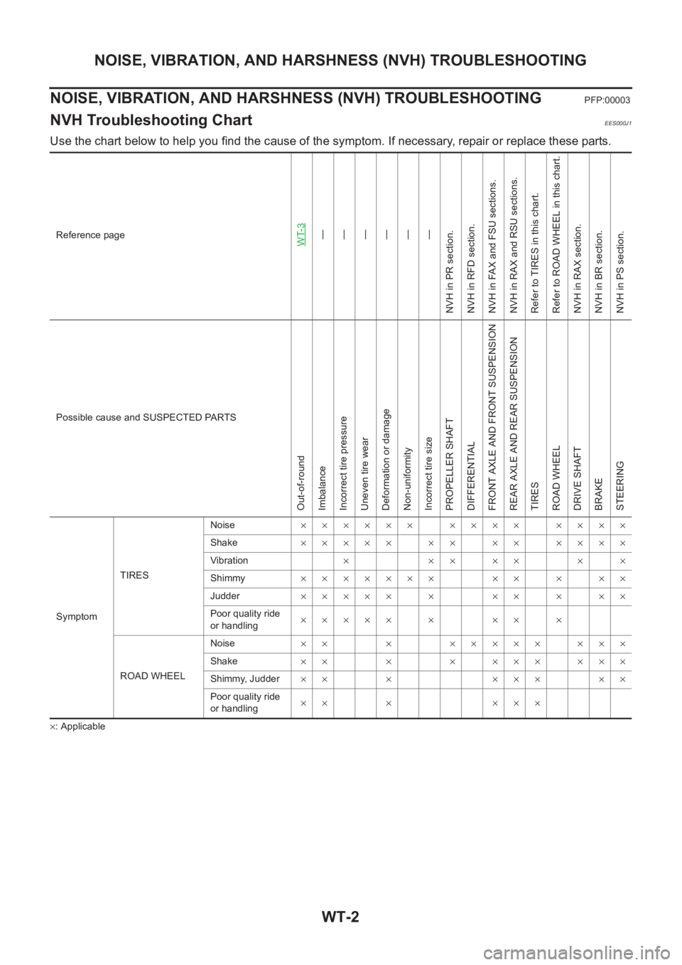
Use the chart below to help you find the cause of the symptom. If necessary, repair or replace these parts.
×: ApplicableReference page
WT-3—
—
—
—
—
—
NVH in PR section.
NVH in RFD section.
NVH in FAX and FSU sections.
NVH in RAX and RSU sections.
Refer to TIRES in this chart.
Refer to ROAD WHEEL in this chart.
NVH in RAX section.
NVH in BR section.
NVH in PS section.
Possible cause and SUSPECTED PARTS
Out-of-round
Imbalance
Incorrect tire pressure
Uneven tire wear
Deformation or damage
Non-uniformity
Incorrect tire size
PROPELLER SHAFT
DIFFERENTIAL
FRONT AXLE AND FRONT SUSPENSION
REAR AXLE AND REAR SUSPENSION
TIRES
ROAD WHEEL
DRIVE SHAFT
BRAKE
STEERING
SymptomTIRESNoise×××××× ×××× ××××
Shake××××× ×× ×× ××××
Vibration×××××××
Shimmy××××××× ×× × ××
Judder××××× × ×× × ××
Poor quality ride
or handling××××× × ×× ×
ROAD WHEELNoise×× × ××××× ×××
Shake×× × × ××× ×××
Shimmy, Judder×× × ××× ××
Poor quality ride
or handling×× × ×××
Page 2737 of 3833
ROAD WHEEL
WT-3
C
D
F
G
H
I
J
K
L
MA
B
WT
ROAD WHEELPFP:40300
InspectionEES000J2
ALUMINUM WHEEL
1. Check tires for wear and improper inflation.
2. Check wheels for deformation, cracks and other damage. If
deformed, remove wheel and check wheel runout.
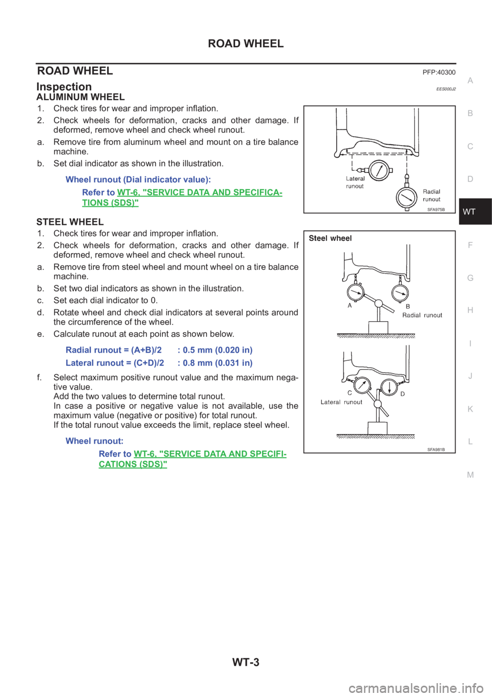
a. Remove tire from aluminum wheel and mount on a tire balance
machine.
b. Set dial indicator as shown in the illustration.
STEEL WHEEL
1. Check tires for wear and improper inflation.
2. Check wheels for deformation, cracks and other damage. If
deformed, remove wheel and check wheel runout.
a. Remove tire from steel wheel and mount wheel on a tire balance
machine.
b. Set two dial indicators as shown in the illustration.
c. Set each dial indicator to 0.
d. Rotate wheel and check dial indicators at several points around
the circumference of the wheel.
e. Calculate runout at each point as shown below.
f. Select maximum positive runout value and the maximum nega-
tive value.
Add the two values to determine total runout.
In case a positive or negative value is not available, use the
maximum value (negative or positive) for total runout.
If the total runout value exceeds the limit, replace steel wheel. Wheel runout (Dial indicator value):
Refer to WT-6, "
SERVICE DATA AND SPECIFICA-
TIONS (SDS)"SFA975B
Radial runout = (A+B)/2 : 0.5 mm (0.020 in)
Lateral runout = (C+D)/2 : 0.8 mm (0.031 in)
Wheel runout:
Refer to WT-6, "
SERVICE DATA AND SPECIFI-
CATIONS (SDS)"
SFA981B
Page 2739 of 3833
ROAD WHEEL TIRE ASSEMBLY
WT-5
C
D
F
G
H
I
J
K
L
MA
B
WT
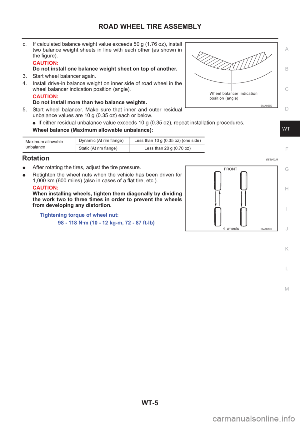
c. If calculated balance weight value exceeds 50 g (1.76 oz), install
two balance weight sheets in line with each other (as shown in
the figure).
CAUTION:
Do not install one balance weight sheet on top of another.
3. Start wheel balancer again.
4. Install drive-in balance weight on inner side of road wheel in the
wheel balancer indication position (angle).
CAUTION:
Do not install more than two balance weights.
5. Start wheel balancer. Make sure that inner and outer residual
unbalance values are 10 g (0.35 oz) each or below.
●If either residual unbalance value exceeds 10 g (0.35 oz), repeat installation procedures.
Wheel balance (Maximum allowable unbalance):
RotationEES000J3
●After rotating the tires, adjust the tire pressure.
●Retighten the wheel nuts when the vehicle has been driven for
1,000 km (600 miles) (also in cases of a flat tire, etc.).
CAUTION:
When installing wheels, tighten them diagonally by dividing
the work two to three times in order to prevent the wheels
from developing any distortion.
Maximum allowable
unbalanceDynamic (At rim flange) Less than 10 g (0.35 oz) (one side)
Static (At rim flange) Less than 20 g (0.70 oz)
SMA056D
Tightening torque of wheel nut:
98 - 118 N·m (10 - 12 kg-m, 72 - 87 ft-lb)
SMA829C
Page 2745 of 3833
NOISE, VIBRATION, AND HARSHNESS (NVH) TROUBLESHOOTING
BR-5
C
D
E
G
H
I
J
K
L
MA
B
BR
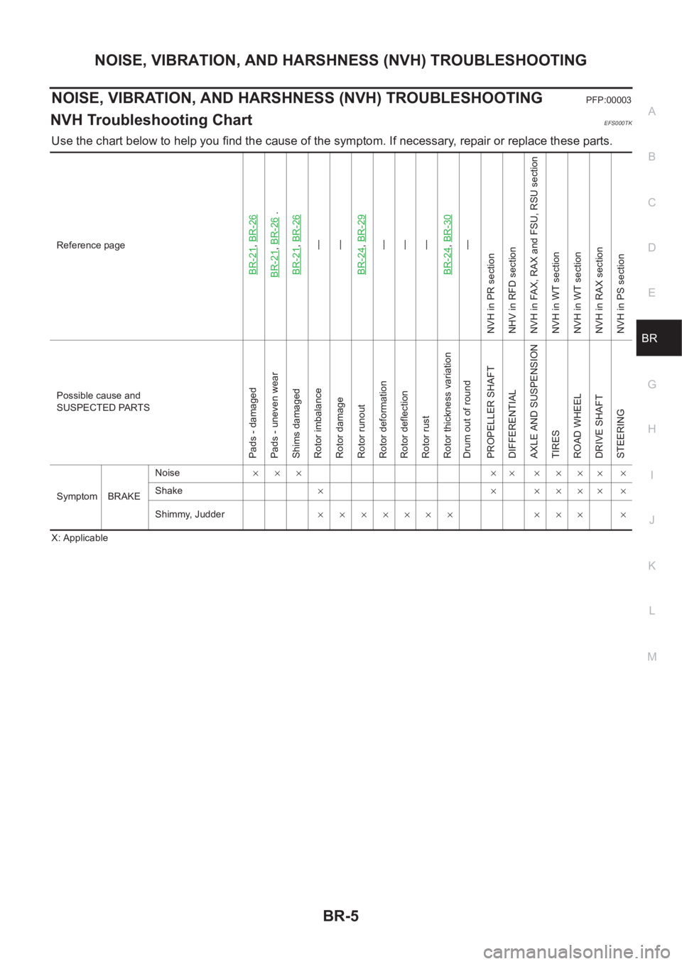
NOISE, VIBRATION, AND HARSHNESS (NVH) TROUBLESHOOTINGPFP:00003
NVH Troubleshooting ChartEFS000TK
Use the chart below to help you find the cause of the symptom. If necessary, repair or replace these parts.
X: ApplicableReference page
BR-21
,BR-26
BR-21
,BR-26
.
BR-21
,BR-26—
—
BR-24,BR-29—
—
—
BR-24,BR-30—
NVH in PR section
NHV in RFD section
NVH in FAX, RAX and FSU, RSU section
NVH in WT section
NVH in WT section
NVH in RAX section
NVH in PS section
Possible cause and
SUSPECTED PARTS
Pads - damaged
Pads - uneven wear
Shims damaged
Rotor imbalance
Rotor damage
Rotor runout
Rotor deformation
Rotor deflection
Rotor rust
Rotor thickness variation
Drum out of round
PROPELLER SHAFT
DIFFERENTIAL
AXLE AND SUSPENSION
TIRES
ROAD WHEEL
DRIVE SHAFT
STEERING
Symptom BRAKENoise××× ×× ×××
××
Shake×××××
××
Shimmy, Judder××××××× ××× ×
Page 2776 of 3833
PB-2
NOISE, VIBRATION, AND HARSHNESS (NVH) TROUBLESHOOTING
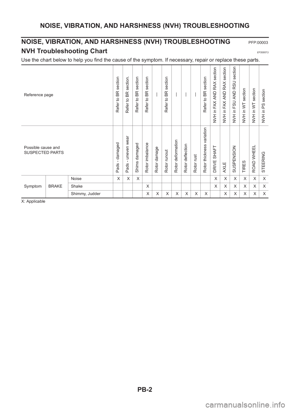
NOISE, VIBRATION, AND HARSHNESS (NVH) TROUBLESHOOTING
PFP:00003
NVH Troubleshooting ChartEFS000TJ
Use the chart below to help you find the cause of the symptom. If necessary, repair or replace these parts.
X: ApplicableReference page
Refer to BR section
Refer to BR section.
Refer to BR section
Refer to BR section
—
Refer to BR section
—
—
—
Refer to BR section
NVH in FAX AND RAX section
NVH in FAX AND RAX section
NVH in FSU AND RSU section
NVH in WT section
NVH in WT section
NVH in PS section
Possible cause and
SUSPECTED PARTS
Pads - damaged
Pads - uneven wear
Shims damaged
Rotor imbalance
Rotor damage
Rotor runout
Rotor deformation
Rotor deflection
Rotor rust
Rotor thickness variation
DRIVE SHAFT
AXLE
SUSPENSION
TIRES
ROAD WHEEL
STEERING
Symptom BRAKENoise XXX XXXXXX
Shake X XXXXXX
Shimmy, JudderXXXXXXX XXXXX
Page 2788 of 3833
![NISSAN X-TRAIL 2001 Service Repair Manual BRC-4
[4WD/ABS]
PRECAUTIONS
[4WD/ABS]PRECAUTIONSPFP:00001
Precautions for brake systemEFS001B6
●Recommended fluid is brake fluid “DOT 3 ”or “DOT 4”.
●Never reuse drained brake fluid.
●Be NISSAN X-TRAIL 2001 Service Repair Manual BRC-4
[4WD/ABS]
PRECAUTIONS
[4WD/ABS]PRECAUTIONSPFP:00001
Precautions for brake systemEFS001B6
●Recommended fluid is brake fluid “DOT 3 ”or “DOT 4”.
●Never reuse drained brake fluid.
●Be](/manual-img/5/57405/w960_57405-2787.png)
BRC-4
[4WD/ABS]
PRECAUTIONS
[4WD/ABS]PRECAUTIONSPFP:00001
Precautions for brake systemEFS001B6
●Recommended fluid is brake fluid “DOT 3 ”or “DOT 4”.
●Never reuse drained brake fluid.
●Be careful not to splash brake fluid on painted areas.
●To clean or wash all parts of master cylinder, disc brake caliper and wheel cylinder, use clean brake fluid.
●Never use mineral oils such as gasoline or kerosene. They will ruin rubber parts of the hydraulic system.
●Use flare nut wrench when removing and installing brake tube.
●Always torque brake lines when installing.
●Burnish the brake contact surfaces after refinishing or replacing
drums or rotors, after replacing pads or linings, or if a soft pedal
occurs at very low mileage. Refer to BR-10, "
Brake Burnishing
Procedure" .
●Before working, turn OFF ignition switch. Disconnect connectors
for ABS actuator and control module or battery terminals.
WARNING:
●Clean brake pads and shoes with a waste cloth, then wipe
with a dust collector.
Precautions for brake controlEFS001B7
●If malfunction is indicated by 4WD warning lamp and/or ABS warning lamp, collect necessary information
from customer (what symptoms are present under what conditions). Find out possible causes before start-
ing service. Besides electrical system inspection, check operation of ABS actuator.
●If malfunction is detected, proceed to trouble diagnosis after checking tire pressure and tire wear.
●Stopping distance or steering stability may be deteriorated by the following conditions. Tire size and type
are in improper combination. Brake pads are not Nissan genuine parts.
●Fitting tires of different size on vehicle can be cause of longitudinal vibration. Always use tires of the same
size and brand. Exchange front and rear tires on the following conditions: Longitudinal vibration occurs in
vehicle with tires of the same size and brand. After replacement, perform trouble diagnosis. 1580|None
●4WD/ABS function may have a failure or error under following condition: There is radio, antenna, or
antenna lead-in wire (including wiring) near control module.
●If aftermarket parts (e.g. Car stereo equipment, CD player) have been installed, check electrical har-
nesses for pinches, open, and improper wiring.
SBR820BA
Page 2825 of 3833
![NISSAN X-TRAIL 2001 Service Repair Manual TROUBLE DIAGNOSIS
BRC-41
[4WD/ABS]
C
D
E
G
H
I
J
K
L
MA
B
BRC
4WD MODES CANNOT BE SWITCHED AFTER ENGINE IS STARTED
1.INSPECTION USING 4WD MODE CHANGE-OVER SWITCH
●Drive modes cannot be switched afte NISSAN X-TRAIL 2001 Service Repair Manual TROUBLE DIAGNOSIS
BRC-41
[4WD/ABS]
C
D
E
G
H
I
J
K
L
MA
B
BRC
4WD MODES CANNOT BE SWITCHED AFTER ENGINE IS STARTED
1.INSPECTION USING 4WD MODE CHANGE-OVER SWITCH
●Drive modes cannot be switched afte](/manual-img/5/57405/w960_57405-2824.png)
TROUBLE DIAGNOSIS
BRC-41
[4WD/ABS]
C
D
E
G
H
I
J
K
L
MA
B
BRC
4WD MODES CANNOT BE SWITCHED AFTER ENGINE IS STARTED
1.INSPECTION USING 4WD MODE CHANGE-OVER SWITCH
●Drive modes cannot be switched after the engine is started.
●On data monitor screen of the CONSULT-II, check 4WD mode switch.
●Check if the display changes from ## to 2WD mode when the 2WD switch is pressed.
●Check if the display changes from ## to AUTO mode when the AUTO switch is pressed.
●Check if the display changes from ## to LOCK mode when the LOCK switch is pressed.
OK or NG
OK >> No malfunction detected.
NG >>
●CONSULT-II display does not change from ## when the 2WD switch is pressed. Check harness
of the 2WD switch.
●CONSULT-II display does not change from ## when the AUTO switch is pressed. Check har-
ness of the 2WD switch and LOCK switch.
●CONSULT-II display does not change from ## when the LOCK switch is pressed. Check har-
ness of the LOCK switch.
●Perform 4WD mode change-over switch inspection.
WHILE DRIVING, 4WD WARNING LAMP FLASHES RAPIDLY. (WHEN IT FLASHERS FOR
APPROX. ONE MINUTE, THEN DOES NOT ILLUMINATE.)
●While driving, 4WD warning lamp flashes rapidly. (When it flashes for Approx. One minute, then does not
illuminate.)
Rapid flashing: 2 times/second
This phenomenon protects drivetrain parts when a heavy load is applied to the electronically controlled
coupling and multiple disc clutch temperature increases. It is not a malfunction.
When the difference of revolution speed by or with the front and rear wheel with AUTO mode, the shift
switch occasionally changes to LOCK mode automatically. This is not a malfunction.
When the difference of revolution speed between the front and rear wheel with AUTO mode, the shift
switch occasionally changes to LOCK mode automatically. This is not a malfunction.
WHILE DRIVING, 4WD WARNING LAMP FLASHES SLOWLY. (WHEN IT CONTINUES TO ILLU-
MINATE UNTIL ENGINE TURNS OFF.)
1. Check using the data monitor function of the CONSULT-II.
●Perform inspection with the data monitor function of the CONSULT-II.
●Check if the value of IMPROPER SIZE TIRE MONITOR is 8 mm (0.31 in) or more.
●Stop the engine. Restart the engine and drive the vehicle at 20 km/h (12 MPH) or faster for approxi-
mately 200 seconds. Confirm the 4WD warning lamp flashes slowly.
(Check if the value of IMPROPER SIZE TIRE MONITOR is 8 mm (0.31 in) or more.)
When the tire size is normal, the value of IMPROPER SIZE TIRE MONITOR will change from 8 mm
(0.31 in) or more to 0 to 4 mm (0 to 0.16 in) (normal condition) after the vehicle is driven 20 km/h (12
MPH) or faster for approximately 5 seconds.
2. Tire inspection
●Inspection of tire pressure
●Wear condition
●Check size of the front and rear tires. (No excessive difference should be observed.) Refer to GI-44,
"Wheels & Tires"
VEHICLE DOES NOT ENTER 4WD MODE EVEN THOUGH 4WD WARNING LAMP IS OFF.
1. Check using the data monitor function of the CONSULT-II.
Perform inspection by the data monitor function of the CONSULT-II.
–Check if the vehicle operation changes to 2WD, AUTO, and LOCK modes.
–Check current supplied to the 4WD solenoid valve in AUTO mode.
2. Check using the active test function of the CONSULT-II.Accelerator pedal not depressed : Approx. 0 A
Accelerator pedal depressed : Approx. 2.8 A