2001 NISSAN X-TRAIL tires
[x] Cancel search: tiresPage 2830 of 3833
![NISSAN X-TRAIL 2001 Service Repair Manual BRC-46
[4WD/ABS]
TROUBLE DIAGNOSIS
●Stop the engine. Restart the engine and drive the vehicle at 20 km/h or faster for approximately 200
seconds. Confirm the 4WD warning lamp flashe NISSAN X-TRAIL 2001 Service Repair Manual BRC-46
[4WD/ABS]
TROUBLE DIAGNOSIS
●Stop the engine. Restart the engine and drive the vehicle at 20 km/h or faster for approximately 200
seconds. Confirm the 4WD warning lamp flashe](/manual-img/5/57405/w960_57405-2829.png)
BRC-46
[4WD/ABS]
TROUBLE DIAGNOSIS
●Stop the engine. Restart the engine and drive the vehicle at 20 km/h or faster for approximately 200
seconds. Confirm the 4WD warning lamp flashes slowly.
(Check if the value of IMPROPER SIZE TIRE MONITOR is 8 mm or more.)
When the tire size is normal, the value of IMPROPER SIZE TIRE MONITOR will change from 8 mm or
more to 0 - 4 mm (normal condition) after the vehicle is driven 20 km/h or faster for approximately 5
seconds.
2. Tire inspection
●Inspection of tire air pressure
●Wear condition
●Check size of the front and rear tires. (No excessive difference should be observed.) Refer to GI-44,
"Wheels & Tires"
Vehicle Does Not Enter 4WD Mode Even Though 4WD Warning Lamp Is OFF.EFS001BX
1. Check using the data monitor function of the CONSULT.
Perform inspection by the data monitor function of the CONSULT.
–Check if the vehicle operation changes to 2WD, AUTO, and LOCK modes.
–Check current supplied to the E-TS solenoid valve in AUTO mode.
2. Check using the active test function of the CONSULT.
Using active test mode of CONSULT, supply current to the E-TS solenoid valve and check that the monitor
current becomes close to this supply current.
●The 4WD/ABS control unit is normal when the difference between E-TS solenoid valve current and the
monitor current is within ±10%.
It is necessary to inspect the electronically controlled coupling assembly.
Tight-corner Braking Symptom Occurs When The Vehicle Is Started In Auto
Mode (4WD Warning Lamp Remain OFF).
EFS001BY
1. THROTTLE POSITION SENSOR AND HARNESS INSPECTION
Check accelerator pedal stroke.
Is inspection result OK?
YES >> Perform self-diagnosis again.
NO >> Malfunctioning throttle position sensor harness
E-TS Actuator Relay (4WD Solenoid Actuator Relay) Turns ON/OFF Frequently.EFS001BZ
1. SELF-DIAGNOSIS RESULT IS E-TS ACTUATOR RELAY (4WD ACTUATOR RELAY) ON ERROR AND
OFF ERROR
Is self-diagnosis result [ON error and OFF error]?
Is inspection result OK?
YES >> GO TO 2.
NO >> Repair or replace as necessary.
2. E-TS ACTUATOR RELAY (4WD SOLENOID ACTUATOR RELAY) AND HARNESS INSPECTION
Is self-diagnosis result [ON error and OFF error]?
Is inspection result OK?
YES >> Perform self-diagnosis again.
NO >> Malfunctioning E-TS actuator relay (4WD solenoid actuator relay) harness Accelerator pedal not depressed : Approx. 0 A
Accelerator pedal depressed : Approx. 2.8 A
Example) Monitor value becomes Approx. 1 A for E-TS solenoid current 1 A setting.
Page 2841 of 3833
![NISSAN X-TRAIL 2001 Service Repair Manual ON-VEHICLE SERVICE
BRC-57
[ESP/TCS/ABS]
C
D
E
G
H
I
J
K
L
MA
B
BRC
ON-VEHICLE SERVICEPFP:00000
Adjustment of Neutral Position of Steering Wheel Angle SensorEFS0019R
●After removing/installing or r NISSAN X-TRAIL 2001 Service Repair Manual ON-VEHICLE SERVICE
BRC-57
[ESP/TCS/ABS]
C
D
E
G
H
I
J
K
L
MA
B
BRC
ON-VEHICLE SERVICEPFP:00000
Adjustment of Neutral Position of Steering Wheel Angle SensorEFS0019R
●After removing/installing or r](/manual-img/5/57405/w960_57405-2840.png)
ON-VEHICLE SERVICE
BRC-57
[ESP/TCS/ABS]
C
D
E
G
H
I
J
K
L
MA
B
BRC
ON-VEHICLE SERVICEPFP:00000
Adjustment of Neutral Position of Steering Wheel Angle SensorEFS0019R
●After removing/installing or replacing the ESP/TCS/ABS control unit, steering wheel angle sensor, steer-
ing components, suspension components, and tires, or after adjusting the wheel alignment, make sure to
adjust the neutral position of the steering wheel angle sensor before running the vehicle.
CAUTION:
To adjust the neutral position of the steering wheel angle sensor, make sure to use CONSULT-II.
(Adjustment cannot be done other than CONSULT-II.)
1. Stop the vehicle with the front wheels in the straight-ahead position.
2. Connect CONSULT-II to data link connector on the vehicle, and
turn the ignition switch to ON position (engine not running).
3. Touch “START”, “ABS”, “WORK SUPPORT” and “ST ANGLE
SENSOR ADJUSTMENT” on the CONSULT-II screen in this
order.
PBIB0196E
SFIA0364E
SFIA0365E
SFIA0370E
Page 2874 of 3833
![NISSAN X-TRAIL 2001 Service Repair Manual BRC-90
[ESP/TCS/ABS]
TROUBLE DIAGNOSIS
ABS Warning Lamp
Touch “ON” and “OFF”on the “ABS WARNING LAMP” screen to check that the ABS warning lamp operates as
follows.
NOTE:
During the active NISSAN X-TRAIL 2001 Service Repair Manual BRC-90
[ESP/TCS/ABS]
TROUBLE DIAGNOSIS
ABS Warning Lamp
Touch “ON” and “OFF”on the “ABS WARNING LAMP” screen to check that the ABS warning lamp operates as
follows.
NOTE:
During the active](/manual-img/5/57405/w960_57405-2873.png)
BRC-90
[ESP/TCS/ABS]
TROUBLE DIAGNOSIS
ABS Warning Lamp
Touch “ON” and “OFF”on the “ABS WARNING LAMP” screen to check that the ABS warning lamp operates as
follows.
NOTE:
During the active test when “OFF” on the “ABS WARNING LAMP” screen is touched, all of the ESP OFF indi-
cator lamp, SLIP indicator lamp, and ABS warning lamp flash once. This is not abnormal.
For Correct and Quick DiagnosisEFS001A8
PRECAUTIONS FOR TROUBLE DIAGNOSIS
●Before performing the trouble diagnosis, always read the GI-3, "PRECAUTIONS" to confirm the general
precautions.
●After replacement of ESP/TCS/ABS control unit, steering wheel angle sensor, steering parts, suspension
parts, or tires, and adjustment of alignment, always adjust the neutral position of steering wheel angle
sensor before driving.
●When the ESP/TCS/ABS control unit is replaced, check that the label on the computer unit is identical
color.
●After completing the trouble diagnosis, always erase the malfunctioning memory. Refer to BRC-81, "Pro-
cedure" .
●When inspection of the continuity or voltage between units is performed, check the connector terminals for
disconnection, looseness, bend, or collapse. If any malfunction is detected, repair or replace the applica-
ble part.
●Intermittent problems may be caused by a malfunction on harness, connector, or terminal. Move the har-
nesses, harness connectors, or terminals by hand to make sure that there is no contact malfunction.
●If a circuit tester is used for the check, be careful not to forcibly extend any connector terminal.
●For self-diagnosis, active test, and work support of ESP/TCS/ABS control unit with CONSULT-II, stop and
connect CONSULT-II and select “ABS”.
●CONSULT-II self-diagnosis results are displayed without regard to occurrence timing. In some case, the
later ones (timing value is small) appear on the next screen.
●While the self-diagnosis results of CONSULT-II shows a malfunction, if CONSULT-II active test is per-
formed, an engine system malfunction may be indicated. In this case, start the engine to resume the nor-
mal screen.
●ESP/TCS/ABS system electronically controls the brake operation and engine output. The following symp-
toms may be caused by the normal operations.
Operation ON OFF
ABS WARNING LAMP ON (Lamp ON) OFF (Lamp OFF)
Symptom Symptom description Result
Motor operation noiseDuring ESP, TCS, or ABS operation, sometimes a faint noise can be
heard. This is a motor operation noise in the ESP actuator.
Normal
Just after the engine starts, the motor operating noise may be heard.
This is a normal status of the system operation check.
System operation check
noiseWhen the engine starts, a“click” noise may be heard from the engine
compartment. This is a normal status of the system operation check.Normal
Page 2914 of 3833
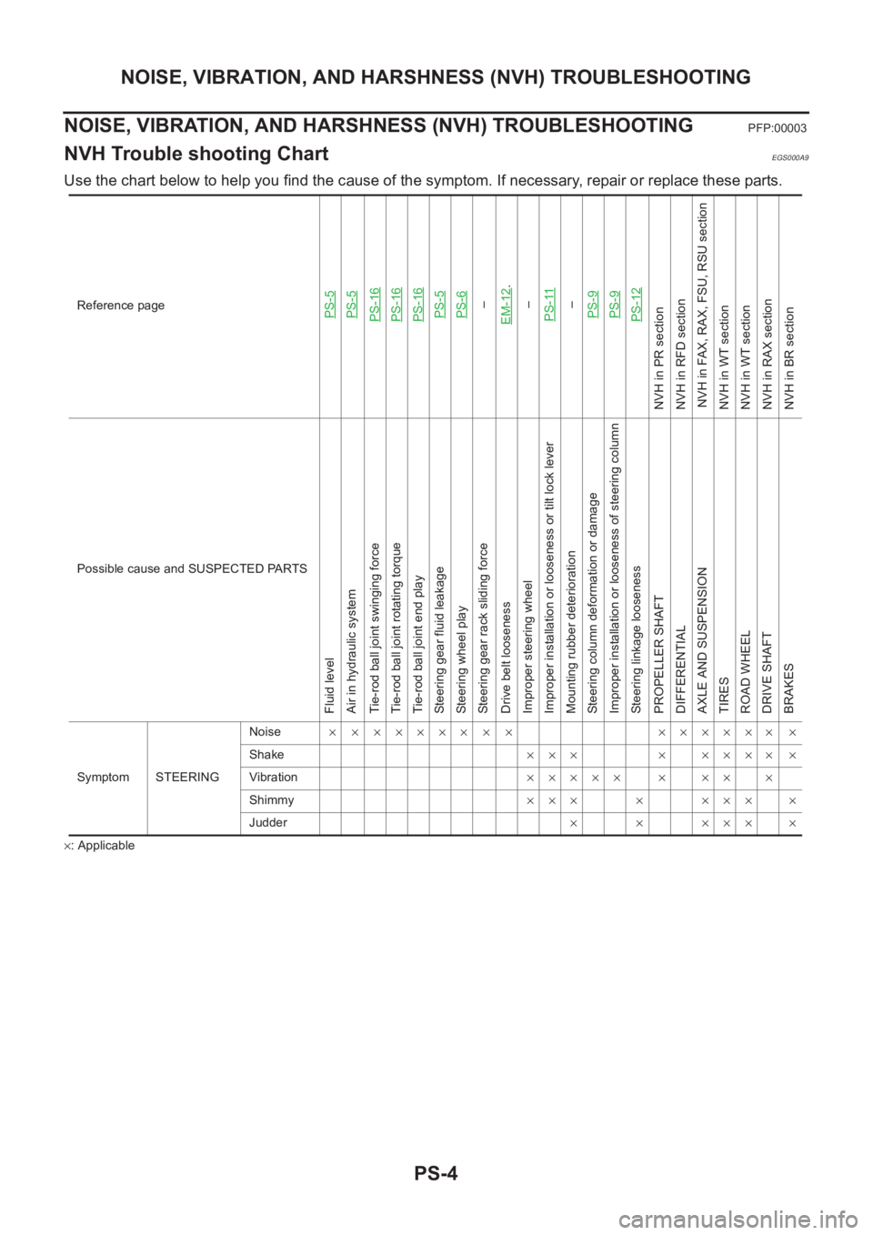
PS-4
NOISE, VIBRATION, AND HARSHNESS (NVH) TROUBLESHOOTING
NOISE, VIBRATION, AND HARSHNESS (NVH) TROUBLESHOOTING
PFP:00003
NVH Trouble shooting ChartEGS000A9
Use the chart below to help you find the cause of the symptom. If necessary, repair or replace these parts.
×: ApplicableReference page
PS-5PS-5PS-16PS-16PS-16PS-5PS-6–
EM-12
.
–
PS-11
–
PS-9PS-9PS-12
NVH in PR section
NVH in RFD section
NVH in FAX, RAX, FSU, RSU section
NVH in WT section
NVH in WT section
NVH in RAX section
NVH in BR section
Possible cause and SUSPECTED PARTS
Fluid level
Air in hydraulic system
Tie-rod ball joint swinging force
Tie-rod ball joint rotating torque
Tie-rod ball joint end play
Steering gear fluid leakage
Steering wheel play
Steering gear rack sliding force
Drive belt looseness
Improper steering wheel
Improper installation or looseness or tilt lock lever
Mounting rubber deterioration
Steering column deformation or damage
Improper installation or looseness of steering column
Steering linkage looseness
PROPELLER SHAFT
DIFFERENTIAL
AXLE AND SUSPENSION
TIRES
ROAD WHEEL
DRIVE SHAFT
BRAKES
Symptom STEERINGNoise× × ××××× × × ×××××× ×
Shake××× × ×××× ×
Vibration××××× × ×× ×
Shimmy××× × ××× ×
Judder× × ××× ×
Page 2950 of 3833
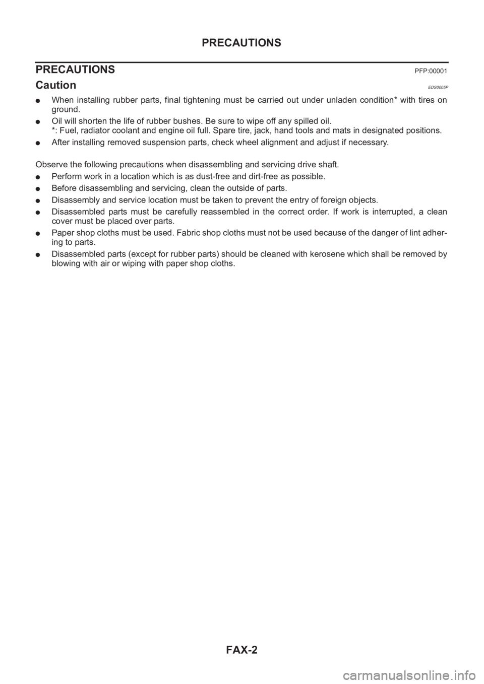
FAX-2
PRECAUTIONS
PRECAUTIONS
PFP:00001
CautionEDS0005P
●When installing rubber parts, final tightening must be carried out under unladen condition* with tires on
ground.
●Oil will shorten the life of rubber bushes. Be sure to wipe off any spilled oil.
*: Fuel, radiator coolant and engine oil full. Spare tire, jack, hand tools and mats in designated positions.
●After installing removed suspension parts, check wheel alignment and adjust if necessary.
Observe the following precautions when disassembling and servicing drive shaft.
●Perform work in a location which is as dust-free and dirt-free as possible.
●Before disassembling and servicing, clean the outside of parts.
●Disassembly and service location must be taken to prevent the entry of foreign objects.
●Disassembled parts must be carefully reassembled in the correct order. If work is interrupted, a clean
cover must be placed over parts.
●Paper shop cloths must be used. Fabric shop cloths must not be used because of the danger of lint adher-
ing to parts.
●Disassembled parts (except for rubber parts) should be cleaned with kerosene which shall be removed by
blowing with air or wiping with paper shop cloths.
Page 2954 of 3833
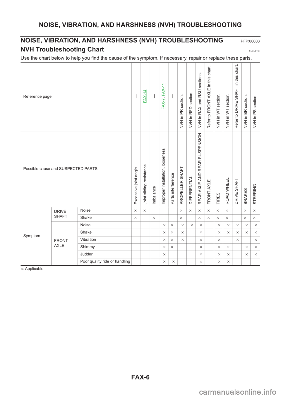
FAX-6
NOISE, VIBRATION, AND HARSHNESS (NVH) TROUBLESHOOTING
NOISE, VIBRATION, AND HARSHNESS (NVH) TROUBLESHOOTING
PFP:00003
NVH Troubleshooting ChartEDS00127
Use the chart below to help you find the cause of the symptom. If necessary, repair or replace these parts.
×: ApplicableReference page
—
FAX-14—
FAX-7,FA X -11—
NVH in PR section.
NVH in RFD section.
NVH in RAX and RSU sections.
Refer to FRONT AXLE in this chart.
NVH in WT section.
NVH in WT section.
Refer to DRIVE SHAFT in this chart.
NVH in BR section.
NVH in PS section.
Possible cause and SUSPECTED PARTS
Excessive joint angle
Joint sliding resistance
Imbalance
Improper installation, looseness
Parts interference
PROPELLER SHAFT
DIFFERENTIAL
REAR AXLE AND REAR SUSPENSION
FRONT AXLE
TIRES
ROAD WHEEL
DRIVE SHAFT
BRAKES
STEERING
SymptomDRIVE
SHAFTNoise×× ×××××× ××
Shake×× ×××××××
FRONT
AXLENoise×× ××× ×××××
Shake×××××××××
Vibration×××××××
Shimmy×× ×××××
Judder× × ×× ××
Poor quality ride or handling×× × ××
Page 2968 of 3833
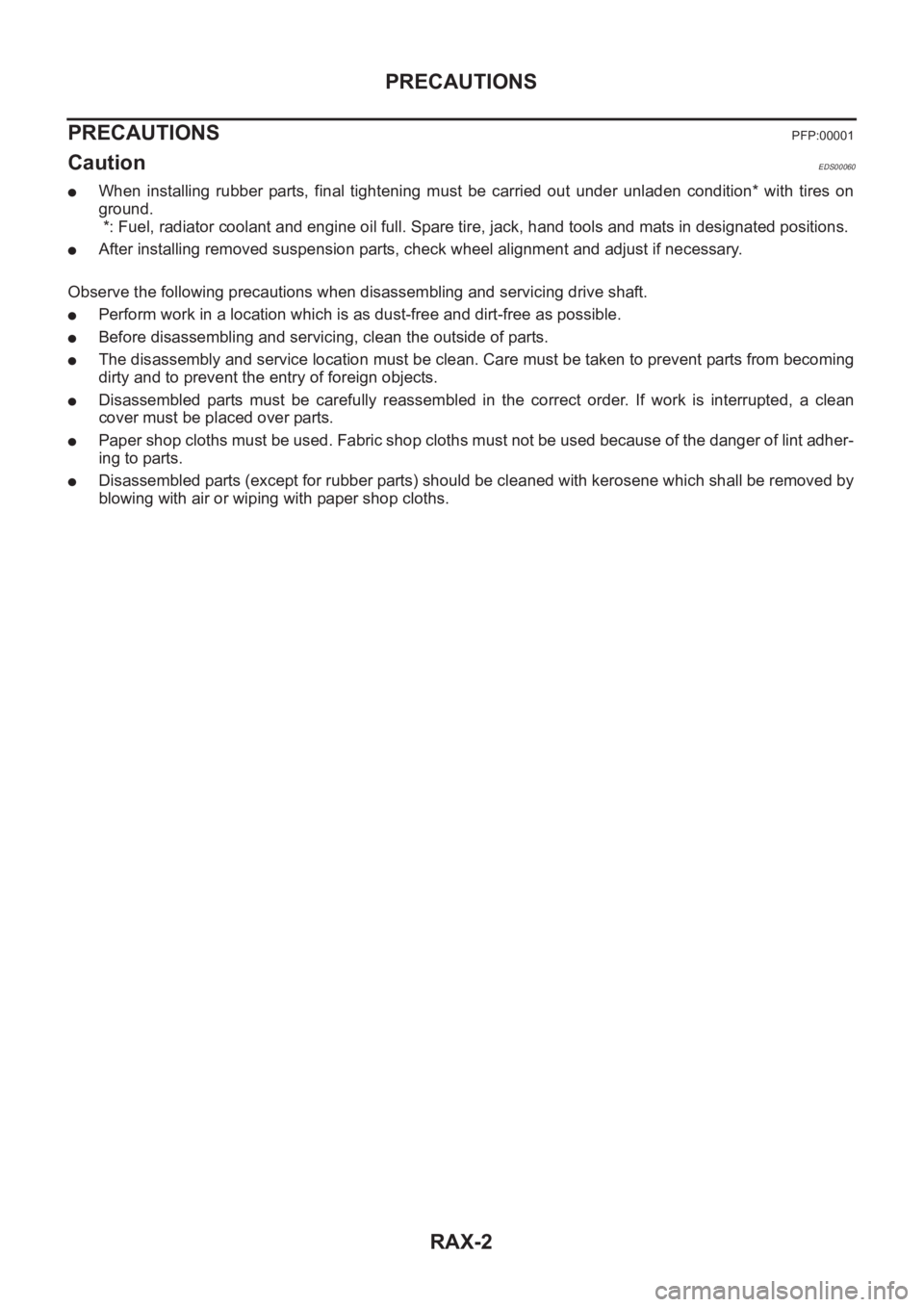
RAX-2
PRECAUTIONS
PRECAUTIONS
PFP:00001
CautionEDS00060
●When installing rubber parts, final tightening must be carried out under unladen condition* with tires on
ground.
*: Fuel, radiator coolant and engine oil full. Spare tire, jack, hand tools and mats in designated positions.
●After installing removed suspension parts, check wheel alignment and adjust if necessary.
Observe the following precautions when disassembling and servicing drive shaft.
●Perform work in a location which is as dust-free and dirt-free as possible.
●Before disassembling and servicing, clean the outside of parts.
●The disassembly and service location must be clean. Care must be taken to prevent parts from becoming
dirty and to prevent the entry of foreign objects.
●Disassembled parts must be carefully reassembled in the correct order. If work is interrupted, a clean
cover must be placed over parts.
●Paper shop cloths must be used. Fabric shop cloths must not be used because of the danger of lint adher-
ing to parts.
●Disassembled parts (except for rubber parts) should be cleaned with kerosene which shall be removed by
blowing with air or wiping with paper shop cloths.
Page 2971 of 3833
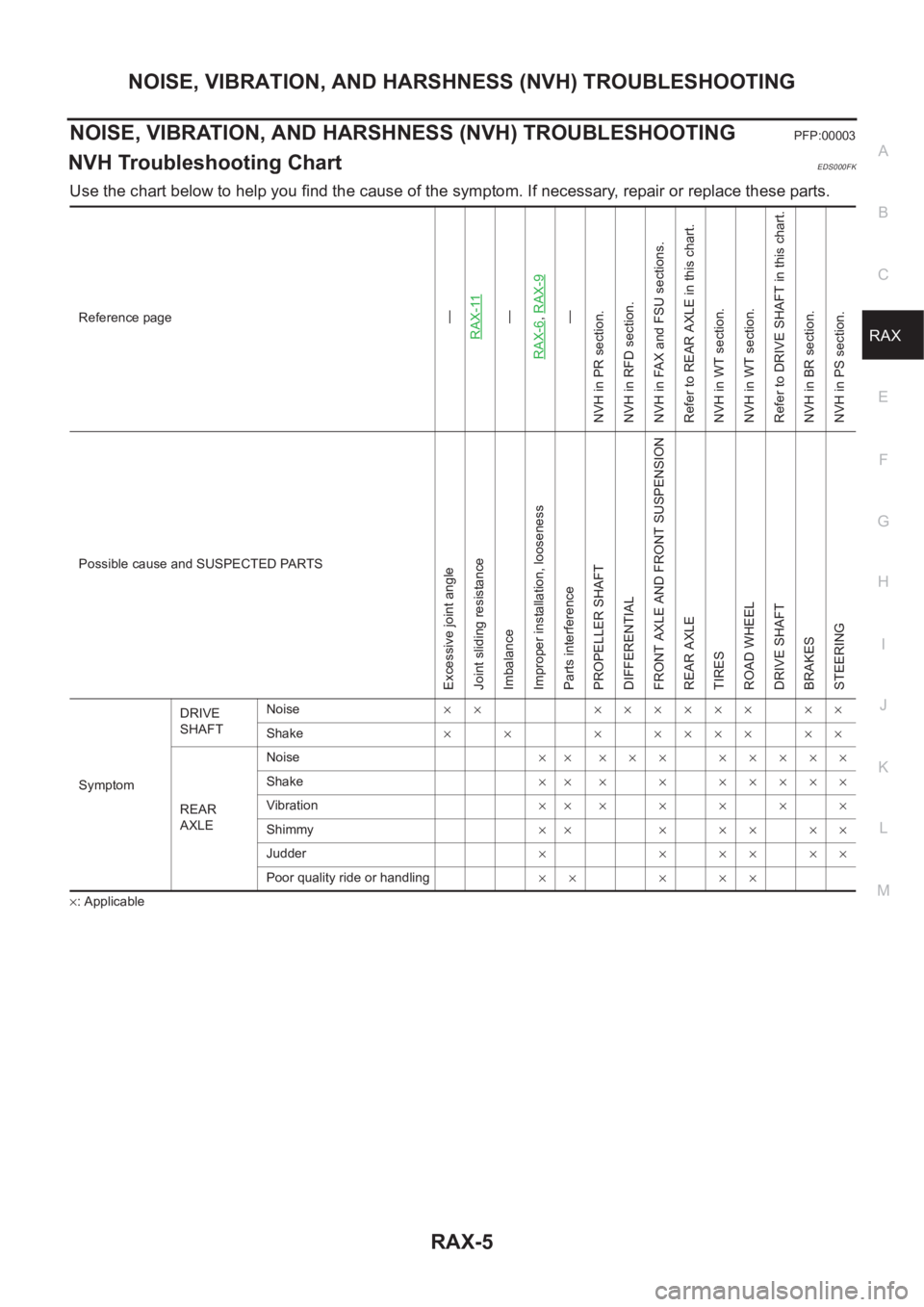
NOISE, VIBRATION, AND HARSHNESS (NVH) TROUBLESHOOTING
RAX-5
C
E
F
G
H
I
J
K
L
MA
B
RAX
NOISE, VIBRATION, AND HARSHNESS (NVH) TROUBLESHOOTINGPFP:00003
NVH Troubleshooting ChartEDS000FK
Use the chart below to help you find the cause of the symptom. If necessary, repair or replace these parts.
×: ApplicableReference page
—
RAX-11—
RAX-6,RAX-9—
NVH in PR section.
NVH in RFD section.
NVH in FAX and FSU sections.
Refer to REAR AXLE in this chart.
NVH in WT section.
NVH in WT section.
Refer to DRIVE SHAFT in this chart.
NVH in BR section.
NVH in PS section.
Possible cause and SUSPECTED PARTS
Excessive joint angle
Joint sliding resistance
Imbalance
Improper installation, looseness
Parts interference
PROPELLER SHAFT
DIFFERENTIAL
FRONT AXLE AND FRONT SUSPENSION
REAR AXLE
TIRES
ROAD WHEEL
DRIVE SHAFT
BRAKES
STEERING
SymptomDRIVE
SHAFTNoise×× ×××××× ××
Shake×× ×××××××
REAR
AXLENoise×× ××× ×××××
Shake×× × × ×××××
Vibration×××××××
Shimmy×× × × × × ×
Judder××××××
Poor quality ride or handling×× × ××