2001 NISSAN X-TRAIL light
[x] Cancel search: lightPage 1 of 3833

MODEL T30 SERIES
© 2002 NISSAN EUROPE S.A.S.
All rights reserved. No part of this Electronic Service Manual may be reproduced or stored in a retrieval system, or transmitted in any
form, or by any means, electronic, mechanical, photocopying, recording or otherwise, without the prior written permission of Nissan
Europe S.A.S., Paris, France.
A GENERAL INFORMATION
B ENGINE
C TRANSMISSION/
TRANSAXLE
D DRIVELINE/AXLE
E SUSPENSION
F BRAKES
G STEERING
H RESTRAINTS
IBODY
J AIR CONDITIONER
K ELECTRICAL
L MAINTENANCE
M INDEXGI General Information
EM Engine Mechanical
LU Engine Lubrication System
CO Engine Cooling System
EC Engine Control System
FL Fuel System
EX Exhaust System
ACC Accelerator Control System
CL Clutch
MT Manual Transaxle
AT Automatic Transaxle
TF Transfer
PR Propeller Shaft
RFD Rear Final Drive
FAX Front Axle
RAX Rear Axle
FSU Front Suspension
RSU Rear Suspension
WT Road Wheels & Tires
BR Brake System
PB Parking Brake System
BRC Brake Control System
PS Power Steering System
SB Seat Belts
SRS Supplemental Restraint System (SRS)
BL Body, Lock & Security System
GW Glasses, Window System & Mirrors
RF Roof
EI Exterior & Interior
IP Instrument Panel
SE Seat
ATC Automatic Air Conditioner
MTC Manual AIr Conditioner
SC Starting & Charging System
LT Lighting System
DI Driver Information System
WW Wiper, Washer & Horn
BCS Body Control System
LAN LAN System
AV Audio, Visual & Telephone System
PG Power Supply, Ground & Circuit Elements
MA Maintenance
IDX Alphabetical Index
QUICK REFERENCE INDEX
A
B
C
D
E
F
G
H
I
J
K
L
M
Page 19 of 3833

HOW TO USE THIS MANUAL
GI-17
C
D
E
F
G
H
I
J
K
L
MB
GI
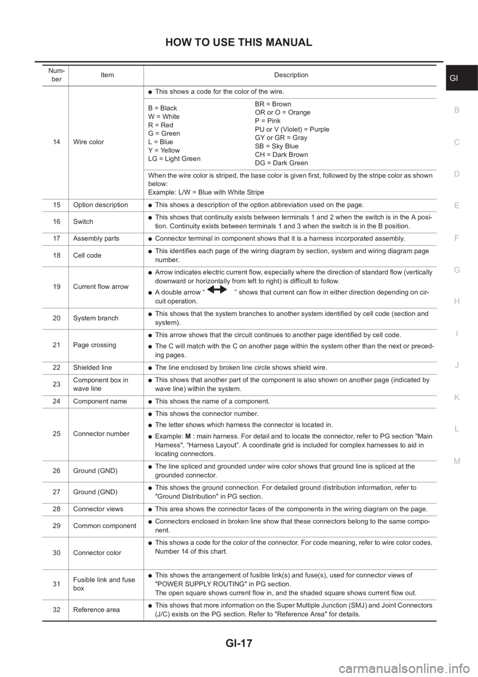
14 Wire color
●This shows a code for the color of the wire.
B = Black
W = White
R = Red
G = Green
L = Blue
Y = Yellow
LG = Light GreenBR = Brown
OR or O = Orange
P = Pink
PU or V (Violet) = Purple
GY or GR = Gray
SB = Sky Blue
CH = Dark Brown
DG = Dark Green
When the wire color is striped, the base color is given first, followed by the stripe color as shown
below:
Example: L/W = Blue with White Stripe
15 Option description
●This shows a description of the option abbreviation used on the page.
16 Switch
●This shows that continuity exists between terminals 1 and 2 when the switch is in the A posi-
tion. Continuity exists between terminals 1 and 3 when the switch is in the B position.
17 Assembly parts
●Connector terminal in component shows that it is a harness incorporated assembly.
18 Cell code
●This identifies each page of the wiring diagram by section, system and wiring diagram page
number.
19 Current flow arrow
●Arrow indicates electric current flow, especially where the direction of standard flow (vertically
downward or horizontally from left to right) is difficult to follow.
●A double arrow “ ” shows that current can flow in either direction depending on cir-
cuit operation.
20 System branch
●This shows that the system branches to another system identified by cell code (section and
system).
21 Page crossing
●This arrow shows that the circuit continues to another page identified by cell code.
●The C will match with the C on another page within the system other than the next or preced-
ing pages.
22 Shielded line
●The line enclosed by broken line circle shows shield wire.
23Component box in
wave line
●This shows that another part of the component is also shown on another page (indicated by
wave line) within the system.
24 Component name
●This shows the name of a component.
25 Connector number
●This shows the connector number.
●The letter shows which harness the connector is located in.
●Example: M : main harness. For detail and to locate the connector, refer to PG section "Main
Harness", “Harness Layout”. A coordinate grid is included for complex harnesses to aid in
locating connectors.
26 Ground (GND)
●The line spliced and grounded under wire color shows that ground line is spliced at the
grounded connector.
27 Ground (GND)
●This shows the ground connection. For detailed ground distribution information, refer to
"Ground Distribution" in PG section.
28 Connector views
●This area shows the connector faces of the components in the wiring diagram on the page.
29 Common component
●Connectors enclosed in broken line show that these connectors belong to the same compo-
nent.
30 Connector color
●This shows a code for the color of the connector. For code meaning, refer to wire color codes,
Number 14 of this chart.
31Fusible link and fuse
box
●This shows the arrangement of fusible link(s) and fuse(s), used for connector views of
"POWER SUPPLY ROUTING" in PG section.
The open square shows current flow in, and the shaded square shows current flow out.
32 Reference area
●This shows that more information on the Super Multiple Junction (SMJ) and Joint Connectors
(J/C) exists on the PG section. Refer to "Reference Area" for details. Num-
berItem Description
Page 26 of 3833

GI-24
SERVICE INFORMATION FOR ELECTRICAL INCIDENT
●Heat sensitive
●Freezing
●Water intrusion
●Electrical load
●Cold or hot start up
Get a thorough description of the incident from the customer. It is important for simulating the conditions of the
problem.
Vehicle Vibration
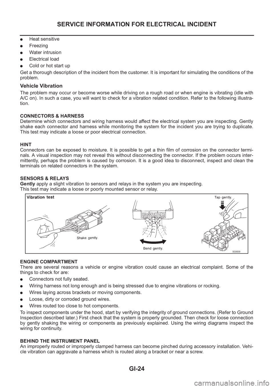
The problem may occur or become worse while driving on a rough road or when engine is vibrating (idle with
A/C on). In such a case, you will want to check for a vibration related condition. Refer to the following illustra-
tion.
CONNECTORS & HARNESS
Determine which connectors and wiring harness would affect the electrical system you are inspecting. Gently
shake each connector and harness while monitoring the system for the incident you are trying to duplicate.
This test may indicate a loose or poor electrical connection.
HINT
Connectors can be exposed to moisture. It is possible to get a thin film of corrosion on the connector termi-
nals. A visual inspection may not reveal this without disconnecting the connector. If the problem occurs inter-
mittently, perhaps the problem is caused by corrosion. It is a good idea to disconnect, inspect and clean the
terminals on related connectors in the system.
SENSORS & RELAYS
Gently apply a slight vibration to sensors and relays in the system you are inspecting.
This test may indicate a loose or poorly mounted sensor or relay.
ENGINE COMPARTMENT
There are several reasons a vehicle or engine vibration could cause an electrical complaint. Some of the
things to check for are:
●Connectors not fully seated.
●Wiring harness not long enough and is being stressed due to engine vibrations or rocking.
●Wires laying across brackets or moving components.
●Loose, dirty or corroded ground wires.
●Wires routed too close to hot components.
To inspect components under the hood, start by verifying the integrity of ground connections. (Refer to Ground
Inspection described later.) First check that the system is properly grounded. Then check for loose connection
by gently shaking the wiring or components as previously explained. Using the wiring diagrams inspect the
wiring for continuity.
BEHIND THE INSTRUMENT PANEL
An improperly routed or improperly clamped harness can become pinched during accessory installation. Vehi-
cle vibration can aggravate a harness which is routed along a bracket or near a screw.
SGI839
Page 30 of 3833

GI-28
SERVICE INFORMATION FOR ELECTRICAL INCIDENT
no voltage; short is further down the circuit than SW1.
●With SW1 closed, relay and solenoid disconnected and the DMM leads across both fuse terminals, check
for voltage.
voltage; short is between SW1 and the relay (point B).
no voltage; short is further down the circuit than the relay.
●With SW1 closed, relay contacts jumped with fused jumper wire check for voltage.
voltage; short is down the circuit of the relay or between the relay and the disconnected solenoid (point C).
no voltage; retrace steps and check power to fuse block.
Ground Inspection
Ground connections are very important to the proper operation of electrical and electronic circuits. Ground
connections are often exposed to moisture, dirt and other corrosive elements. The corrosion (rust) can
become an unwanted resistance. This unwanted resistance can change the way a circuit works.
Electronically controlled circuits are very sensitive to proper grounding. A loose or corroded ground can drasti-
cally affect an electronically controlled circuit. A poor or corroded ground can easily affect the circuit. Even
when the ground connection looks clean, there can be a thin film of rust on the surface.
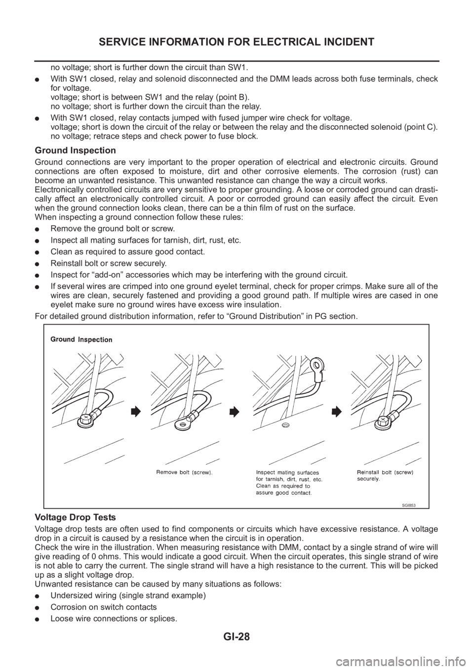
When inspecting a ground connection follow these rules:
●Remove the ground bolt or screw.
●Inspect all mating surfaces for tarnish, dirt, rust, etc.
●Clean as required to assure good contact.
●Reinstall bolt or screw securely.
●Inspect for “add-on” accessories which may be interfering with the ground circuit.
●If several wires are crimped into one ground eyelet terminal, check for proper crimps. Make sure all of the
wires are clean, securely fastened and providing a good ground path. If multiple wires are cased in one
eyelet make sure no ground wires have excess wire insulation.
For detailed ground distribution information, refer to “Ground Distribution” in PG section.
Voltage Drop Tests
Voltage drop tests are often used to find components or circuits which have excessive resistance. A voltage
drop in a circuit is caused by a resistance when the circuit is in operation.
Check the wire in the illustration. When measuring resistance with DMM, contact by a single strand of wire will
give reading of 0 ohms. This would indicate a good circuit. When the circuit operates, this single strand of wire
is not able to carry the current. The single strand will have a high resistance to the current. This will be picked
up as a slight voltage drop.
Unwanted resistance can be caused by many situations as follows:
●Undersized wiring (single strand example)
●Corrosion on switch contacts
●Loose wire connections or splices.
SGI853
Page 32 of 3833

GI-30
SERVICE INFORMATION FOR ELECTRICAL INCIDENT
Control Unit Circuit Test
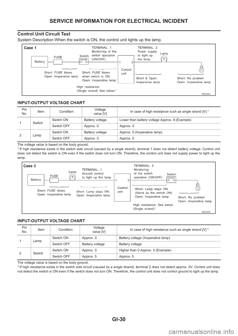
System Description:When the switch is ON, the control unit lights up the lamp.
INPUT-OUTPUT VOLTAGE CHART
The voltage value is based on the body ground.
*:If high resistance exists in the switch side circuit (caused by a single strand), terminal 1 does not detect battery voltage. Control unit
does not detect the switch is ON even if the switch does not turn ON. Therefore, the control unit does not supply power to light up the
lamp.
INPUT-OUTPUT VOLTAGE CHART
The voltage value is based on the body ground.
*:If high resistance exists in the switch side circuit (caused by a single strand), terminal 2 does not detect approx. 0V. Control unit does
not detect the switch is ON even if the switch does not turn ON. Therefore, the control unit does not control ground to light up the lamp.
MGI034A
Pin
No.Item ConditionVoltage
value [V]In case of high resistance such as single strand [V] *
1 SwitchSwitch ON Battery voltage Lower than battery voltage Approx. 8 (Example)
Switch OFF Approx. 0 Approx. 0
2LampSwitch ON Battery voltage Approx. 0 (Inoperative lamp)
Switch OFF Approx. 0 Approx. 0
MGI035A
Pin
No.Item ConditionVo l ta g e
value [V]In case of high resistance such as single strand [V] *
1LampSwitch ON Approx. 0 Battery voltage (Inoperative lamp)
Switch OFF Battery voltage Battery voltage
2 SwitchSwitch ON Approx. 0 Higher than 0 Approx. 4 (Example)
Switch OFF Approx. 5 Approx. 5
Page 48 of 3833

GI-46
TERMINOLOGY
Exhaust gas recirculation control-BPT
valveEGRC-BPT valve BPT valve
Exhaust gas recirculation control-solenoid
valveEGRC-solenoid valve EGR control solenoid valve
Exhaust gas recirculation temperature sen-
sor
EGRT sensor Exhaust gas temperature sensor
EGR temperature sensor
Flash electrically erasable programmable
read only memoryFEEPROM ***
Flash erasable programmable read only
memoryFEPROM ***
Flexible fuel sensor FFS ***
Flexible fuel system FF system ***
Fuel pressure regulator *** Pressure regulator
Fuel pressure regulator control solenoid
valve*** PRVR control solenoid valve
Fuel trim FT ***
Heated Oxygen sensor HO2S Exhaust gas sensor
Idle air control system IAC system Idle speed control
Idle air control valve-air regulator IACV-air regulator Air regulator
Idle air control valve-auxiliary air control
valveIACV-AAC valve Auxiliary air control (AAC) valve
Idle air control valve-FICD solenoid valve IACV-FICD solenoid valve FICD solenoid valve
Idle air control valve-idle up control sole-
noid valveIACV-idle up control solenoid valve Idle up control solenoid valve
Idle speed control-FI pot ISC-FI pot FI pot
Idle speed control system ISC system ***
Ignition control IC ***
Ignition control module ICM ***
Indirect fuel injection system IFI system ***
Intake air IA Air
Intake air temperature sensor IAT sensor Air temperature sensor
Knock *** Detonation
Knock sensor KS Detonation sensor
Malfunction indicator lamp MIL Check engine light
Manifold absolute pressure MAP ***
Manifold absolute pressure sensor MAPS ***
Manifold differential pressure MDP ***
Manifold differential pressure sensor MDPS ***
Manifold surface temperature MST ***
Manifold surface temperature sensor MSTS ***
Manifold vacuum zone MVZ ***
Manifold vacuum zone sensor MVZS ***
Mass air flow sensor MAFS Air flow meter
Mixture control solenoid valve MC solenoid valve Air-fuel ratio control solenoid valve
Multiport fuel injection System MFI system Fuel injection controlNEW TERMNEW ACRONYM /
ABBREVIATIONOLD TERM
Page 56 of 3833
![NISSAN X-TRAIL 2001 Service Repair Manual EM-6
[QR]
PRECAUTIONS
Precautions For Liquid Gasket
EBS00MRW
REMOVAL OF LIQUID GASKET
●After removing the mounting bolts and nuts, separate the mating
surface using a seal cutter and remove t NISSAN X-TRAIL 2001 Service Repair Manual EM-6
[QR]
PRECAUTIONS
Precautions For Liquid Gasket
EBS00MRW
REMOVAL OF LIQUID GASKET
●After removing the mounting bolts and nuts, separate the mating
surface using a seal cutter and remove t](/manual-img/5/57405/w960_57405-55.png)
EM-6
[QR]
PRECAUTIONS
Precautions For Liquid Gasket
EBS00MRW
REMOVAL OF LIQUID GASKET
●After removing the mounting bolts and nuts, separate the mating
surface using a seal cutter and remove the old liquid gasket
sealing.
CAUTION:
Be careful not to damage the mating surfaces.
●In areas where the cutter is difficult to use, use a plastic hammer
to lightly tap the areas where the liquid gasket is applied.
CAUTION:
If for some unavoidable reason a tool such as a flat-blade
screwdriver is used, be careful not to damage the mating
surfaces.
LIQUID GASKET APPLICATION PROCEDURE
1. Using a scraper, remove the old liquid gasket adhering to the liq-
uid gasket application surface and the mating surface.
●Remove the liquid gasket completely from the groove of the
liquid gasket application surface, mounting bolts and bolt
holes.
2. Wipe the liquid gasket application surface and the mating sur-
face with white gasoline (lighting and heating use) to remove
adhering moisture, grease and foreign materials.
3. Attach the liquid gasket to the tube presser.
Use Genuine Liquid Gasket or equivalent.
4. Apply the liquid gasket without breaks to the specified location
with the specified dimensions.
●If there is a groove for the liquid gasket application, apply the
liquid gasket to the groove.
●As for the bolt holes, normally apply the liquid gasket inside
the holes. If specified, it should be applied outside the holes.
Make sure to read the instruction in this manual.
●Within five minutes of liquid gasket application, install the mat-
ing component.
●If the liquid gasket protrudes, wipe it off immediately.
●Do not retighten after the installation.
●After 30 minutes or more have passed from the installation, fill
the engine oil and engine coolant.
CAUTION:
If there are instructions in this manual, observe them.
PBIC0275E
PBIC0003E
EMA0622D
SEM159F
Page 72 of 3833
![NISSAN X-TRAIL 2001 Service Repair Manual EM-22
[QR]
INTAKE MANIFOLD
3. Align center to insert quick connector straightly into fuel tube.
●Insert fuel tube into quick connector until the first spool on fuel
tubes is inserted completely and NISSAN X-TRAIL 2001 Service Repair Manual EM-22
[QR]
INTAKE MANIFOLD
3. Align center to insert quick connector straightly into fuel tube.
●Insert fuel tube into quick connector until the first spool on fuel
tubes is inserted completely and](/manual-img/5/57405/w960_57405-71.png)
EM-22
[QR]
INTAKE MANIFOLD
3. Align center to insert quick connector straightly into fuel tube.
●Insert fuel tube into quick connector until the first spool on fuel
tubes is inserted completely and the second one is positioned
slightly below the quick connectors bottom end.
CAUTION:
●Hold A position in illustration when inserting fuel tube
into quick connector.
●Carefully align center to avoid inclined insertion to pre-
vent damage to O-ring inside quick connector.
●Insert until you hear a “click” sound and actually feel
the engagement.
●To avoid misidentification of engagement with a similar sound, be sure to perform the next
step.
4. Before clamping fuel hose with hose clamps, pull quick connector hard by hand holding A position. Make
sure it is completely engaged (connected) so that it does not come out from fuel tube.
NOTE:
Recommended pulling force is 50 N (5.1 kg, 11.2 lb).
5. Install quick connector cap on quick connector joint.
●Direct arrow mark on quick connector cap to upper side.
6. Install fuel hose to hose clamp.
Connecting Quick Connector of Fuel Hose (Vehicle side)
Install quick connector as follows.
1. Make sure no foreign substances are deposited in and around tube and quick connector and no damage
on them.
2. Align center to insert quick connector straightly into fuel tube.
●Insert fuel tube until a click is heard.
●Install quick connector cap on quick connector joint. Direct
arrow mark on quick connector cap to upper side.
3. Install fuel hose to hose clamp.
INSPECTION AFTER INSTALLATION
Make sure there is no fuel leakage at connections in the following steps.
1. Apply fuel pressure to fuel lines with turning ignition switch ON (with engine stopped). Then check for fuel
leaks at connections.
2. Start the engine and rev it up and check for fuel leaks at connections.
NOTE:
Use mirrors for checking on invisible points.
CAUTION:
Do not touch the engine immediately after stopped as engine becomes extremely hot.
KBIA0272E
KBIA0298E
PBIC0662E