2001 NISSAN X-TRAIL belt
[x] Cancel search: beltPage 3658 of 3833
BCS-2
PRECAUTIONS
PRECAUTIONS
PFP:00011
Precautions for Supplemental Restraint System (SRS) “AIR BAG” and “SEAT
BELT PRE-TENSIONER”
EKS0079N
The Supplemental Restraint System such as “AIR BAG” and “SEAT BELT PRE-TENSIONER”, used along
with a front seat belt, helps to reduce the risk or severity of injury to the driver and front passenger for certain
types of collision. Information necessary to service the system safely is included in the SRS and SB section of
this Service Manual.
WARNING:
●To avoid rendering the SRS inoperative, which could increase the risk of personal injury or death
in the event of a collision which would result in air bag inflation, all maintenance must be per-
formed by an authorized NISSAN/INFINITI dealer.
●Improper maintenance, including incorrect removal and installation of the SRS, can lead to per-
sonal injury caused by unintentional activation of the system. For removal of Spiral Cable and Air
Bag Module, see the SRS section.
●Do not use electrical test equipment on any circuit related to the SRS unless instructed to in this
Service Manual. SRS wiring harnesses can be identified by yellow and/or orange harness connec-
tors.
Wiring Diagrams and Trouble Diagnosis EKS0079O
When you read wiring diagrams, refer to the followings:
●Refer to GI-13, "How to Read Wiring Diagrams" in GI section
●Refer to PG-2, "POWER SUPPLY ROUTING" for power distribution circuit in PG section
When you perform trouble diagnosis, refer to the followings:
●Refer to GI-10, "HOW TO FOLLOW TEST GROUPS IN TROUBLE DIAGNOSES" in PG section
●Refer to GI-23, "How to Perform Efficient Diagnosis for an Electrical Incident" in PG section
Page 3659 of 3833
TIME CONTROL UNIT
BCS-3
C
D
E
F
G
H
I
J
L
MA
B
BCS
TIME CONTROL UNITPFP:28491
DescriptionEKS002ZU
OUTLINE
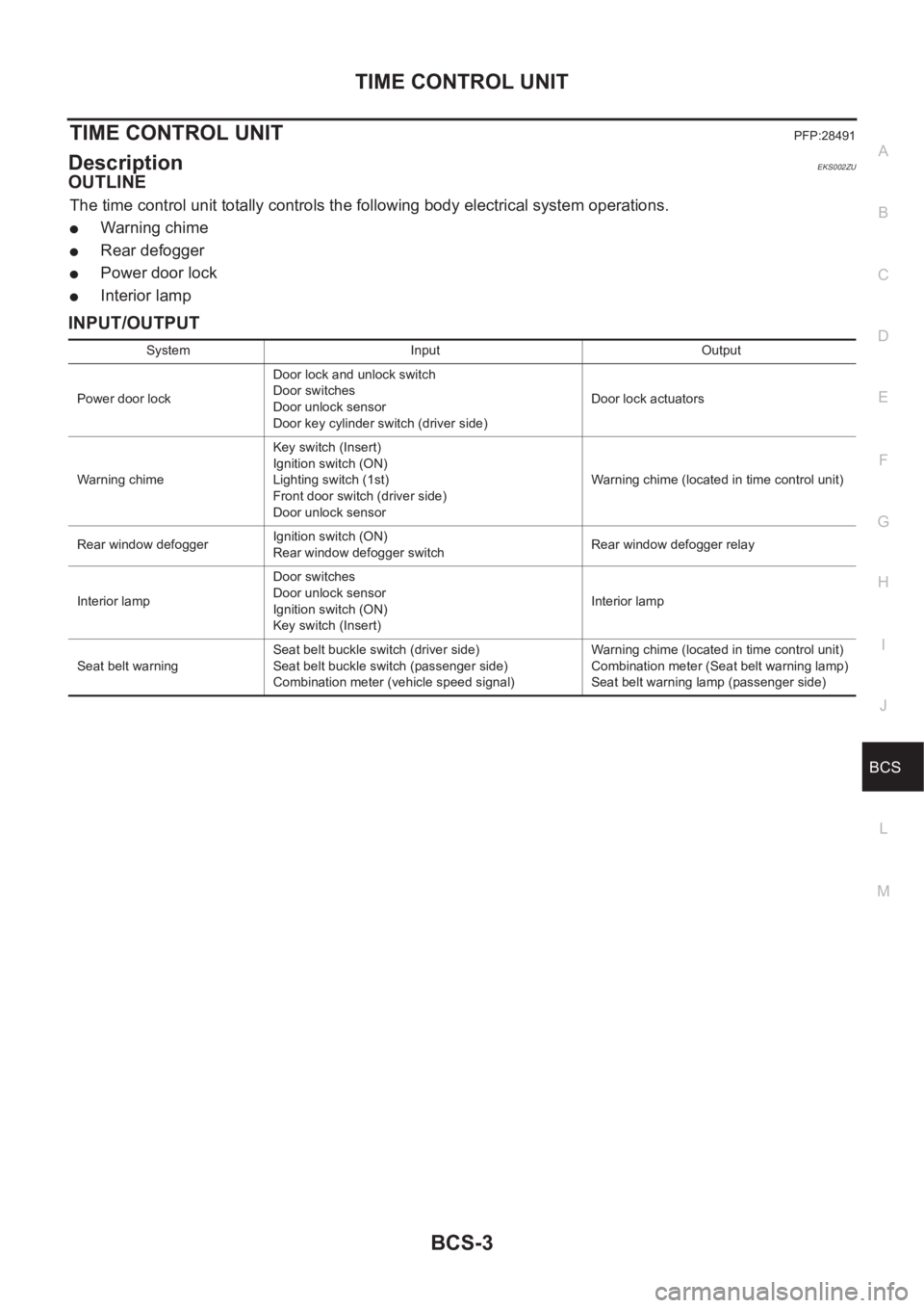
The time control unit totally controls the following body electrical system operations.
●Warning chime
●Rear defogger
●Power door lock
●Interior lamp
INPUT/OUTPUT
System Input Output
Power door lockDoor lock and unlock switch
Door switches
Door unlock sensor
Door key cylinder switch (driver side)Door lock actuators
Warning chimeKey switch (Insert)
Ignition switch (ON)
Lighting switch (1st)
Front door switch (driver side)
Door unlock sensorWarning chime (located in time control unit)
Rear window defoggerIgnition switch (ON)
Rear window defogger switchRear window defogger relay
Interior lampDoor switches
Door unlock sensor
Ignition switch (ON)
Key switch (Insert)Interior lamp
Seat belt warningSeat belt buckle switch (driver side)
Seat belt buckle switch (passenger side)
Combination meter (vehicle speed signal)Warning chime (located in time control unit)
Combination meter (Seat belt warning lamp)
Seat belt warning lamp (passenger side)
Page 3661 of 3833
TIME CONTROL UNIT
BCS-5
C
D
E
F
G
H
I
J
L
MA
B
BCS
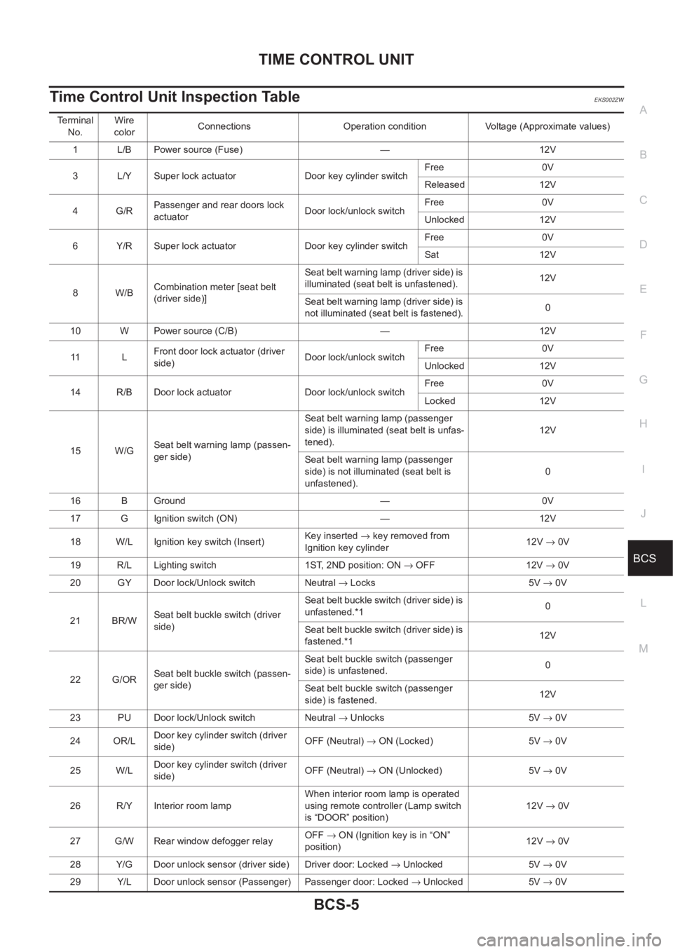
Time Control Unit Inspection TableEKS002ZW
Terminal
No.Wire
colorConnections Operation condition Voltage (Approximate values)
1 L/B Power source (Fuse) — 12V
3 L/Y Super lock actuator Door key cylinder switchFree 0V
Released 12V
4G/RPassenger and rear doors lock
actuatorDoor lock/unlock switchFree 0V
Unlocked 12V
6 Y/R Super lock actuator Door key cylinder switchFree 0V
Sat 12V
8W/BCombination meter [seat belt
(driver side)]Seat belt warning lamp (driver side) is
illuminated (seat belt is unfastened).12V
Seat belt warning lamp (driver side) is
not illuminated (seat belt is fastened).0
10 W Power source (C/B) — 12V
11 LFront door lock actuator (driver
side)Door lock/unlock switchFree 0V
Unlocked 12V
14 R/B Door lock actuator Door lock/unlock switchFree 0V
Locked 12V
15 W/GSeat belt warning lamp (passen-
ger side)Seat belt warning lamp (passenger
side) is illuminated (seat belt is unfas-
tened).12V
Seat belt warning lamp (passenger
side) is not illuminated (seat belt is
unfastened).0
16 B Ground — 0V
17 G Ignition switch (ON) — 12V
18 W/L Ignition key switch (Insert)Key inserted → key removed from
Ignition key cylinder12V → 0V
19 R/L Lighting switch 1ST, 2ND position: ON → OFF 12V → 0V
20 GY Door lock/Unlock switch Neutral → Locks 5V → 0V
21 BR/WSeat belt buckle switch (driver
side)Seat be lt buckle switch (d river side) is
unfastened.*10
Seat be lt buckle switch (d river side) is
fastened.*112V
22 G/ORSeat belt buckle switch (passen-
ger side)Seat belt buckle switch (passenger
side) is unfastened.0
Seat belt buckle switch (passenger
side) is fastened.12V
23 PU Door lock/Unlock switch Neutral → Unlocks 5V → 0V
24 OR/LDoor key cylinder switch (driver
side)OFF (Neutral) → ON (Locked) 5V → 0V
25 W/LDoor key cylinder switch (driver
side)OFF (Neutral) → ON (Unlocked) 5V → 0V
26 R/Y Interior room lampWhen interior room lamp is operated
using remote controller (Lamp switch
is “DOOR” position)12V → 0V
27 G/W Rear window defogger relayOFF→ ON (Ignition key is in “ON”
position)12V → 0V
28 Y/G Door unlock sensor (driver side) Driver door: Locked → Unlocked 5V → 0V
29 Y/L Door unlock sensor (Passenger) Passenger door: Locked → Unlocked 5V → 0V
Page 3663 of 3833
LAN-1
LAN SYSTEM
K ELECTRICAL
CONTENTS
C
D
E
F
G
H
I
J
L
M
SECTION
A
B
LAN
LAN SYSTEM
CAN
PRECAUTIONS .......................................................... 2
Precautions for Supplemental Restraint System
(SRS) “AIR BAG” and “SEAT BELT PRE-TEN-
SIONER” .................................................................. 2
Precautions For Trouble Diagnosis .......................... 2
CAN SYSTEM ....................................................... 2
Precautions For Harness Repair .............................. 2
CAN SYSTEM ....................................................... 2
CAN COMMUNICATION ............................................ 3
System Description .................................................. 3
FOR A/T MODELS ................................................ 3
FOR M/T MODELS ............................................... 3
CAN SYSTEM (FOR A/T MODELS) ........................... 5
System Description .................................................. 5
Component Parts and Harness Connector Location ..... 5
Wiring Diagram — CAN — ....................................... 6
Work Flow ................................................................ 7
CHECK SHEET ..................................................... 8
CHECK SHEET RESULTS (EXAMPLE) ............... 9
INSPECTION ........................................................ 9CAN Communication Circuit Check .......................... 9
Component Inspection ............................................ 11
ECM/TCM INTERNAL CIRCUIT INSPECTION ... 11
CAN SYSTEM (FOR M/T MODELS) ........................ 12
System Description ................................................. 12
Component Parts and Harness Connector Location ... 12
Wiring Diagram — CAN — ..................................... 13
Work Flow ............................................................... 14
CHECK SHEET ................................................... 15
CHECK SHEET RESULTS (EXAMPLE) ............. 16
INSPECTION ...................................................... 17
Circuit Check Between Steering Wheel Angle Sen-
sor and 4WD Control Unit ....................................... 17
ECM Circuit Check .............................................. ... 18
4WD Control Unit Circuit Check ............................. 19
Steering Wheel Angle Sensor Circuit Check .......... 20
ESP/TCS/ABS Control Unit Circuit Check .............. 20
CAN Communication Circuit Check ........................ 21
Component Inspection ............................................ 25
ECM / ESP/TCS/ABS CONTROL UNIT INTER-
NAL CIRCUIT INSPECTION ............................... 25
Page 3664 of 3833
![NISSAN X-TRAIL 2001 Service Repair Manual LAN-2
[CAN]
PRECAUTIONS
[CAN]PRECAUTIONSPFP:00001
Precautions for Supplemental Restraint System (SRS) “AIR BAG” and “SEAT
BELT PRE-TENSIONER”
EKS001U0
The Supplemental Restraint System su NISSAN X-TRAIL 2001 Service Repair Manual LAN-2
[CAN]
PRECAUTIONS
[CAN]PRECAUTIONSPFP:00001
Precautions for Supplemental Restraint System (SRS) “AIR BAG” and “SEAT
BELT PRE-TENSIONER”
EKS001U0
The Supplemental Restraint System su](/manual-img/5/57405/w960_57405-3663.png)
LAN-2
[CAN]
PRECAUTIONS
[CAN]PRECAUTIONSPFP:00001
Precautions for Supplemental Restraint System (SRS) “AIR BAG” and “SEAT
BELT PRE-TENSIONER”
EKS001U0
The Supplemental Restraint System such as “AIR BAG” and “SEAT BELT PRE-TENSIONER”, used along
with a front seat belt, helps to reduce the risk or severity of injury to the driver and front passenger for certain
types of collision. Information necessary to service the system safely is included in the SRS and SB section of
this Service Manual.
WARNING:
●To avoid rendering the SRS inoperative, which could increase the risk of personal injury or death
in the event of a collision which would result in air bag inflation, all maintenance must be per-
formed by an authorized NISSAN/INFINITI dealer.
●Improper maintenance, including incorrect removal and installation of the SRS, can lead to per-
sonal injury caused by unintentional activation of the system. For removal of Spiral Cable and Air
Bag Module, see the SRS section.
●Do not use electrical test equipment on any circuit related to the SRS unless instructed to in this
Service Manual. SRS wiring harnesses can be identified by yellow and/or orange harness connec-
tors.
Precautions For Trouble DiagnosisEKS001U1
CAN SYSTEM
●Do not apply voltage of 7.0V or higher to the measurement terminals.
●Use the tester with its open terminal voltage being 7.0V or less.
Precautions For Harness RepairEKS001U2
CAN SYSTEM
●Solder the repaired parts, and wrap with tape. [Frays of twisted
line must be within 110 mm (4.33 in)]
●Do not perform bypass wire connections for the repair parts.
(The spliced wire will become separated and the characteristics
of twisted line will be lost.)
PKIA0306E
PKIA0307E
Page 3689 of 3833
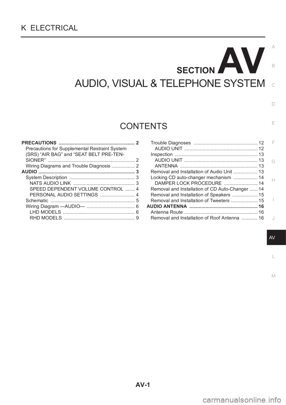
AV-1
AUDIO, VISUAL & TELEPHONE SYSTEM
K ELECTRICAL
CONTENTS
C
D
E
F
G
H
I
J
L
M
SECTION
A
B
AV
AUDIO, VISUAL & TELEPHONE SYSTEM
PRECAUTIONS .......................................................... 2
Precautions for Supplemental Restraint System
(SRS) “AIR BAG” and “SEAT BELT PRE-TEN-
SIONER” .................................................................. 2
Wiring Diagrams and Trouble Diagnosis .................. 2
AUDIO ......................................................................... 3
System Description .................................................. 3
NATS AUDIO LINK ............................................... 3
SPEED DEPENDENT VOLUME CONTROL ........ 4
PERSONAL AUDIO SETTINGS ........................... 4
Schematic ................................................................ 5
Wiring Diagram —AUDIO— ..................................... 6
LHD MODELS ....................................................... 6
RHD MODELS ...................................................... 9Trouble Diagnoses ................................................. 12
AUDIO UNIT ..................................................... ... 12
Inspection ............................................................... 13
AUDIO UNIT ..................................................... ... 13
ANTENNA ........................................................ ... 13
Removal and Installation of Audio Unit ................... 13
Locking CD auto-changer mechanism ................... 14
DAMPER LOCK PROCEDURE .......................... 14
Removal and Installation of CD Auto-Changer ....... 14
Removal and Installation of Speakers .................... 15
Removal and Installation of Tweeters ..................... 15
AUDIO ANTENNA .................................................... 16
Antenna Route ........................................................ 16
Removal and Installation of Roof Antenna ............. 16
Page 3690 of 3833
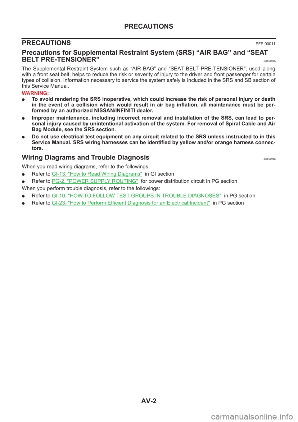
AV-2
PRECAUTIONS
PRECAUTIONS
PFP:00011
Precautions for Supplemental Restraint System (SRS) “AIR BAG” and “SEAT
BELT PRE-TENSIONER”
EKS0036C
The Supplemental Restraint System such as “AIR BAG” and “SEAT BELT PRE-TENSIONER”, used along
with a front seat belt, helps to reduce the risk or severity of injury to the driver and front passenger for certain
types of collision. Information necessary to service the system safely is included in the SRS and SB section of
this Service Manual.
WARNING:
●To avoid rendering the SRS inoperative, which could increase the risk of personal injury or death
in the event of a collision which would result in air bag inflation, all maintenance must be per-
formed by an authorized NISSAN/INFINITI dealer.
●Improper maintenance, including incorrect removal and installation of the SRS, can lead to per-
sonal injury caused by unintentional activation of the system. For removal of Spiral Cable and Air
Bag Module, see the SRS section.
●Do not use electrical test equipment on any circuit related to the SRS unless instructed to in this
Service Manual. SRS wiring harnesses can be identified by yellow and/or orange harness connec-
tors.
Wiring Diagrams and Trouble Diagnosis EKS0036D
When you read wiring diagrams, refer to the followings:
●Refer to GI-13, "How to Read Wiring Diagrams" in GI section
●Refer to PG-2, "POWER SUPPLY ROUTING" for power distribution circuit in PG section
When you perform trouble diagnosis, refer to the followings:
●Refer to GI-10, "HOW TO FOLLOW TEST GROUPS IN TROUBLE DIAGNOSES" in PG section
●Refer to GI-23, "How to Perform Efficient Diagnosis for an Electrical Incident" in PG section
Page 3766 of 3833
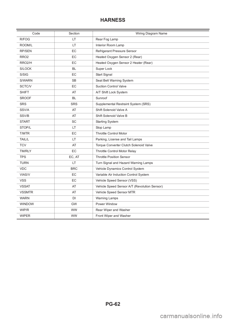
PG-62
HARNESS
R/FOG LT Rear Fog Lamp
ROOM/L LT Interior Room Lamp
RP/SEN EC Refrigerant Pressure Sensor
RRO2 EC Heated Oxygen Sensor 2 (Rear)
RRO2/H EC Heated Oxygen Sensor 2 Heater (Rear)
S/LOCK BL Super Lock
S/SIG EC Start Signal
S/WARN SB Seat Belt Warning System
SCTC/V EC Suction Control Valve
SHIFT AT A/T Shift Lock System
SROOF BL Sunroof
SRS SRS Supplemental Restraint System (SRS)
SSV/A AT Shift Solenoid Valve A
SSV/B AT Shift Solenoid Valve B
START SC Starting System
STOP/L LT Stop Lamp
T/MTR EC Throttle Control Motor
TAIL/L LT Parking, License and Tail Lamps
TCV AT Torque Converter Clutch Solenoid Valve
TM/RLY EC Throttle Control Motor Relay
TPS EC, AT Throttle Position Sensor
TURN LT Turn Signal and Hazard Warning Lamps
VDC BRC Vehicle Dynamics Control System
VIAS/V EC Variable Air Induction Control System
VSS EC Vehicle Speed Sensor (VSS)
VSSAT AT Vehicle Speed Sensor A/T (Revolution Sensor)
VSSMTR AT Vehicle Speed Sensor MTR
WARN DI Warning Lamps
WINDOW GW Power Window
WIP/R WW Rear Wiper and Washer
WIPER WW Front Wiper and WasherCode Section Wiring Diagram Name