2001 NISSAN X-TRAIL belt
[x] Cancel search: beltPage 3428 of 3833
MTC-2
PRECAUTIONS
PRECAUTIONS
PFP:00001
Precautions for Supplemental Restraint System (SRS) “AIR BAG” and “SEAT
BELT PRE-TENSIONER”
EJS0028D
The Supplemental Restraint System such as “AIR BAG” and “SEAT BELT PRE-TENSIONER”, used along
with a front seat belt, helps to reduce the risk or severity of injury to the driver and front passenger for certain
types of collision. Information necessary to service the system safely is included in the SRS and SB section of
this Service Manual.
WARNING:
●To avoid rendering the SRS inoperative, which could increase the risk of personal injury or death
in the event of a collision which would result in air bag inflation, all maintenance must be per-
formed by an authorized NISSAN/INFINITI dealer.
●Improper maintenance, including incorrect removal and installation of the SRS, can lead to per-
sonal injury caused by unintentional activation of the system. For removal of Spiral Cable and Air
Bag Module, see the SRS section.
●Do not use electrical test equipment on any circuit related to the SRS unless instructed to in this
Service Manual. SRS wiring harnesses can be identified by yellow and/or orange harness connec-
tors.
Wiring Diagrams and Trouble DiagnosisEJS000WA
When you read wiring diagrams, refer to the following:
●GI-13, "How to Read Wiring Diagrams" in GI section.
●PG-3, "Wiring Diagram — POWER —" in EL section.
When you perform trouble diagnosis, refer to the following:
●GI-9, "How to Follow Trouble Diagnoses" in GI section.
●GI-23, "How to Perform Efficient Diagnosis for an Electrical Incident" in GI section.
Page 3457 of 3833
SC-1
STARTING & CHARGING SYSTEM
K ELECTRICAL
CONTENTS
C
D
E
F
G
H
I
J
L
M
SECTION
A
B
SC
STARTING & CHARGING SYSTEM
PRECAUTIONS .......................................................... 2
Precautions for Supplemental Restraint System
(SRS) “AIR BAG” and “SEAT BELT PRE-TEN-
SIONER” .................................................................. 2
Wiring Diagrams and Trouble Diagnosis .................. 2
BATTERY .................................................................... 3
How to Handle Battery ............................................. 3
METHODS OF PREVENTING OVER-DIS-
CHARGE ............................................................... 3
CHECKING ELECTROLYTE LEVEL .................... 3
SPECIFIC GRAVITY CHECK ............................... 4
Battery Test and Charging Chart .............................. 5
CHART I ................................................................ 5
CHART II ............................................................... 6
A: SLOW CHARGE ............................................... 7
B: STANDARD CHARGE ...................................... 8
C: QUICK CHARGE ............................................ 10
Removal and Installation ......................................... 11
CHARGING SYSTEM ............................................... 12
System Description ................................................ 12
Wiring Diagram — CHARGE — ............................. 13
Trouble Diagnoses ................................................. 14
WITH IC REGULATOR ....................................... 14
MALFUNCTION INDICATOR .............................. 14
Removal and Installation ........................................ 15
REMOVAL (QR ENGINE MODELS) ................... 15
REMOVAL (YD ENGINE MODELS) ................... 15
INSTALLATION ................................................... 15
Disassembly and Assembly ................................... 16
Disassembly ........................................................... 17
REAR COVER .................................................... 17
REAR BEARING ................................................. 18Inspection ............................................................... 18
ROTOR CHECK .................................................. 18
BRUSH CHECK .................................................. 18
PULLEY CHECK(WITH CLUTCH TYPE) ............ 18
STATOR CHECK ................................................. 18
Assembly ................................................................ 19
RING FITTING IN REAR BEARING .................... 19
REAR COVER INSTALLATION ........................... 19
STARTING SYSTEM ................................................. 20
System Description ................................................. 20
M/T MODELS ...................................................... 20
A/T MODELS ....................................................... 20
Wiring Diagram — START —/M/T models ............. 21
Wiring Diagram — START —/A/T models .............. 22
Trouble Diagnoses ..............................................
... 23
Removal and Installation ........................................ 24
REMOVAL ........................................................... 24
INSTALLATION ................................................... 24
Disassembly and Assembly .................................... 25
Inspection ............................................................... 28
MAGNETIC SWITCH CHECK ............................. 28
PINION/CLUTCH CHECK ................................... 28
BRUSH CHECK .................................................. 28
YOKE CHECK ..................................................... 29
ARMATURE CHECK ........................................... 30
Assembly ................................................................ 31
PINION PROTRUSION LENGTH ADJUST-
MENT .................................................................. 31
SERVICE DATA AND SPECIFICATIONS (SDS) ...... 33
Battery .................................................................... 33
Starter ..................................................................... 33
Alternator ................................................................ 33
Page 3458 of 3833
SC-2
PRECAUTIONS
PRECAUTIONS
PFP:00011
Precautions for Supplemental Restraint System (SRS) “AIR BAG” and “SEAT
BELT PRE-TENSIONER”
EKS007AR
The Supplemental Restraint System such as “AIR BAG” and “SEAT BELT PRE-TENSIONER”, used along
with a front seat belt, helps to reduce the risk or severity of injury to the driver and front passenger for certain
types of collision. Information necessary to service the system safely is included in the SRS and SB section of
this Service Manual.
WARNING:
●To avoid rendering the SRS inoperative, which could increase the risk of personal injury or death
in the event of a collision which would result in air bag inflation, all maintenance must be per-
formed by an authorized NISSAN/INFINITI dealer.
●Improper maintenance, including incorrect removal and installation of the SRS, can lead to per-
sonal injury caused by unintentional activation of the system. For removal of Spiral Cable and Air
Bag Module, see the SRS section.
●Do not use electrical test equipment on any circuit related to the SRS unless instructed to in this
Service Manual. SRS wiring harnesses can be identified by yellow and/or orange harness connec-
tors.
Wiring Diagrams and Trouble Diagnosis EKS00312
When you read wiring diagrams, refer to the followings:
●Refer to GI-13, "How to Read Wiring Diagrams" in GI section
●Refer to PG-2, "POWER SUPPLY ROUTING" for power distribution circuit in PG section
When you perform trouble diagnosis, refer to the followings:
●Refer to GI-10, "HOW TO FOLLOW TEST GROUPS IN TROUBLE DIAGNOSES" in GI section
●Refer to GI-23, "How to Perform Efficient Diagnosis for an Electrical Incident" in GI section
Page 3471 of 3833
CHARGING SYSTEM
SC-15
C
D
E
F
G
H
I
J
L
MA
B
SC
Removal and Installation EKS0031A
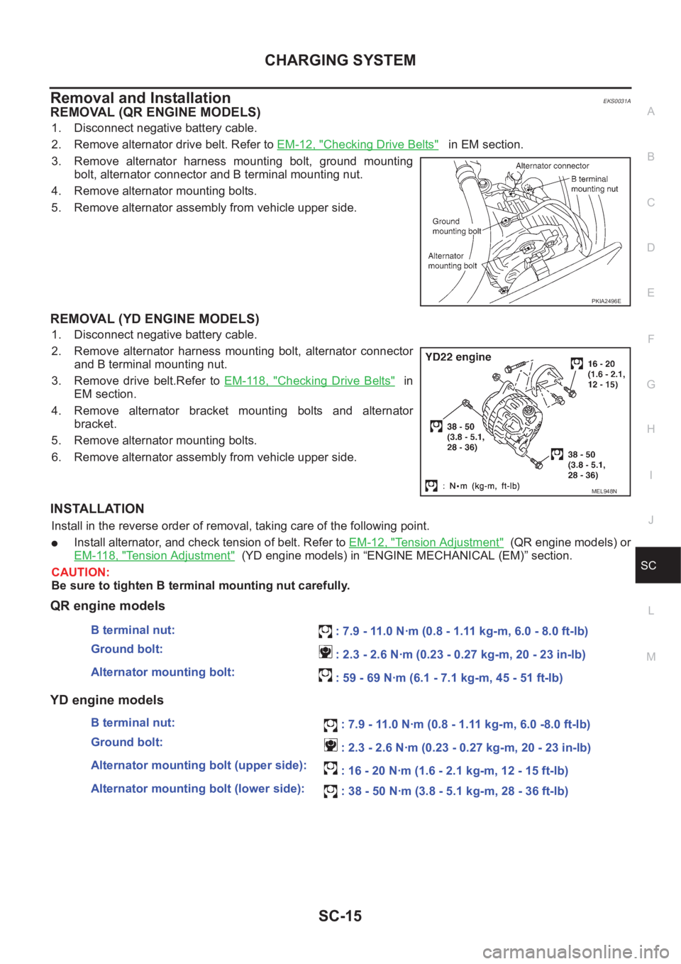
REMOVAL (QR ENGINE MODELS)
1. Disconnect negative battery cable.
2. Remove alternator drive belt. Refer to EM-12, "
Checking Drive Belts" in EM section.
3. Remove alternator harness mounting bolt, ground mounting
bolt, alternator connector and B terminal mounting nut.
4. Remove alternator mounting bolts.
5. Remove alternator assembly from vehicle upper side.
REMOVAL (YD ENGINE MODELS)
1. Disconnect negative battery cable.
2. Remove alternator harness mounting bolt, alternator connector
and B terminal mounting nut.
3. Remove drive belt.Refer to EM-118, "
Checking Drive Belts" in
EM section.
4. Remove alternator bracket mounting bolts and alternator
bracket.
5. Remove alternator mounting bolts.
6. Remove alternator assembly from vehicle upper side.
INSTALLATION
Install in the reverse order of removal, taking care of the following point.
●Install alternator, and check tension of belt. Refer to EM-12, "Tension Adjustment" (QR engine models) or
EM-118, "
Tension Adjustment" (YD engine models) in “ENGINE MECHANICAL (EM)” section.
CAUTION:
Be sure to tighten B terminal mounting nut carefully.
QR engine models
YD engine models
PKIA2496E
MEL948N
B terminal nut:
: 7.9 - 11.0 N·m (0.8 - 1.11 kg-m, 6.0 - 8.0 ft-lb)
Ground bolt:
: 2.3 - 2.6 N·m (0.23 - 0.27 kg-m, 20 - 23 in-lb)
Alternator mounting bolt:
: 59 - 69 N·m (6.1 - 7.1 kg-m, 45 - 51 ft-lb)
B terminal nut:
: 7.9 - 11.0 N·m (0.8 - 1.11 kg-m, 6.0 -8.0 ft-lb)
Ground bolt:
: 2.3 - 2.6 N·m (0.23 - 0.27 kg-m, 20 - 23 in-lb)
Alternator mounting bolt (upper side):
: 16 - 20 N·m (1.6 - 2.1 kg-m, 12 - 15 ft-lb)
Alternator mounting bolt (lower side):
: 38 - 50 N·m (3.8 - 5.1 kg-m, 28 - 36 ft-lb)
Page 3491 of 3833
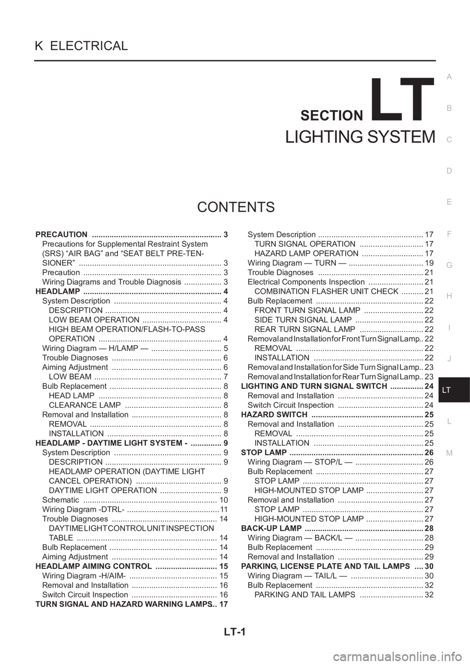
LT-1
LIGHTING SYSTEM
K ELECTRICAL
CONTENTS
C
D
E
F
G
H
I
J
L
M
SECTION
A
B
LT
LIGHTING SYSTEM
PRECAUTION ............................................................ 3
Precautions for Supplemental Restraint System
(SRS) “AIR BAG” and “SEAT BELT PRE-TEN-
SIONER” .................................................................. 3
Precaution ................................................................ 3
Wiring Diagrams and Trouble Diagnosis .................. 3
HEADLAMP ................................................................ 4
System Description .................................................. 4
DESCRIPTION ...................................................... 4
LOW BEAM OPERATION ..................................... 4
HIGH BEAM OPERATION/FLASH-TO-PASS
OPERATION ......................................................... 4
Wiring Diagram — H/LAMP — ................................. 5
Trouble Diagnoses ................................................... 6
Aiming Adjustment ................................................... 6
LOW BEAM ........................................................... 7
Bulb Replacement .................................................... 8
HEAD LAMP ......................................................... 8
CLEARANCE LAMP ............................................. 8
Removal and Installation .......................................... 8
REMOVAL ............................................................. 8
INSTALLATION ..................................................... 8
HEADLAMP - DAYTIME LIGHT SYSTEM - ............... 9
System Description .................................................. 9
DESCRIPTION ...................................................... 9
HEADLAMP OPERATION (DAYTIME LIGHT
CANCEL OPERATION) ........................................ 9
DAYTIME LIGHT OPERATION ............................. 9
Schematic .............................................................. 10
Wiring Diagram -DTRL- ........................................... 11
Trouble Diagnoses ................................................. 14
DAYTIME LIGHT CONTROL UNIT INSPECTION
TABLE ................................................................. 14
Bulb Replacement .................................................. 14
Aiming Adjustment ................................................. 14
HEADLAMP AIMING CONTROL ............................. 15
Wiring Diagram -H/AIM- ......................................... 15
Removal and Installation ........................................ 16
Switch Circuit Inspection ........................................ 16
TURN SIGNAL AND HAZARD WARNING LAMPS ... 17System Description ................................................. 17
TURN SIGNAL OPERATION .............................. 17
HAZARD LAMP OPERATION ............................. 17
Wiring Diagram — TURN — ................................... 19
Trouble Diagnoses ................................................. 21
Electrical Components Inspection .......................... 21
COMBINATION FLASHER UNIT CHECK ........
... 21
Bulb Replacement .................................................. 22
FRONT TURN SIGNAL LAMP ............................ 22
SIDE TURN SIGNAL LAMP ................................ 22
REAR TURN SIGNAL LAMP .............................. 22
Removal and Installation for Front Turn Signal Lamp ... 22
REMOVAL ........................................................... 22
INSTALLATION ................................................... 22
Removal and Installation for Side Turn Signal Lamp ... 23
Removal and Installation for Rear Turn Signal Lamp ... 23
LIGHTING AND TURN SIGNAL SWITCH ................ 24
Removal and Installation ........................................ 24
Switch Circuit Inspection ........................................ 24
HAZARD SWITCH .................................................... 25
Removal and Installation ........................................ 25
REMOVAL ........................................................... 25
INSTALLATION ................................................... 25
STOP LAMP .............................................................. 26
Wiring Diagram — STOP/L — ................................ 26
Bulb Replacement .................................................. 27
STOP LAMP ........................................................ 27
HIGH-MOUNTED STOP LAMP ........................... 27
Removal and Installation ........................................ 27
STOP LAMP ........................................................ 27
HIGH-MOUNTED STOP LAMP ........................... 27
BACK-UP LAMP ....................................................... 28
Wiring Diagram — BACK/L — ................................ 28
Bulb Replacement .................................................. 29
Removal and Installation ........................................ 29
PARKING, LICENSE PLATE AND TAIL LAMPS ..... 30
Wiring Diagram — TAIL/L — .................................. 30
Bulb Replacement .................................................. 32
PARKING AND TAIL LAMPS .............................. 32
Page 3493 of 3833
PRECAUTION
LT-3
C
D
E
F
G
H
I
J
L
MA
B
LT
PRECAUTION PFP:00011
Precautions for Supplemental Restraint System (SRS) “AIR BAG” and “SEAT
BELT PRE-TENSIONER”
EKS0079M
The Supplemental Restraint System such as “AIR BAG” and “SEAT BELT PRE-TENSIONER”, used along
with a front seat belt, helps to reduce the risk or severity of injury to the driver and front passenger for certain
types of collision. Information necessary to service the system safely is included in the SRS and SB section of
this Service Manual.
WARNING:
●To avoid rendering the SRS inoperative, which could increase the risk of personal injury or death
in the event of a collision which would result in air bag inflation, all maintenance must be per-
formed by an authorized NISSAN/INFINITI dealer.
●Improper maintenance, including incorrect removal and installation of the SRS, can lead to per-
sonal injury caused by unintentional activation of the system. For removal of Spiral Cable and Air
Bag Module, see the SRS section.
●Do not use electrical test equipment on any circuit related to the SRS unless instructed to in this
Service Manual. SRS wiring harnesses can be identified by yellow and/or orange harness connec-
tors.
Precaution EKS003KS
●Do not touch the glass of bulb directly by hand. Keep grease and other oily matters away from it. Do not
touch bulb by hand while it is lit or right after being turned off. Burning may result.
●Do not leave bulb out of headlamp reflector for a long time because dust, moisture smoke, etc. may affect
the performance of the headlamp. When replacing the bulb, be sure to replace it with a new one.
●Adjust aiming by tightening aiming screw. (To adjust it toward loosening side, first loosen adjusting screw,
and then make adjustment by tightening.)
●To remove soil or sealant of bulbs, do not use organic solvent (thinner, gasoline, etc.)
●When replacing bulb, be sure to hold bulb socket and pull it out straight. If wiring harness of the bulb is
pulled at an angle, the bulb may be caught in the lamp, making it difficult to take out.
Wiring Diagrams and Trouble Diagnosis EKS003KT
When you read wiring diagrams, refer to the followings:
●Refer to GI-13, "How to Read Wiring Diagrams" in GI section
●Refer to PG-2, "POWER SUPPLY ROUTING" for power distribution circuit in PG section
When you perform trouble diagnosis, refer to the followings:
●Refer to GI-10, "HOW TO FOLLOW TEST GROUPS IN TROUBLE DIAGNOSES" in GI section
●Refer toGI-23, "How to Perform Efficient Diagnosis for an Electrical Incident" in GI section
Page 3559 of 3833
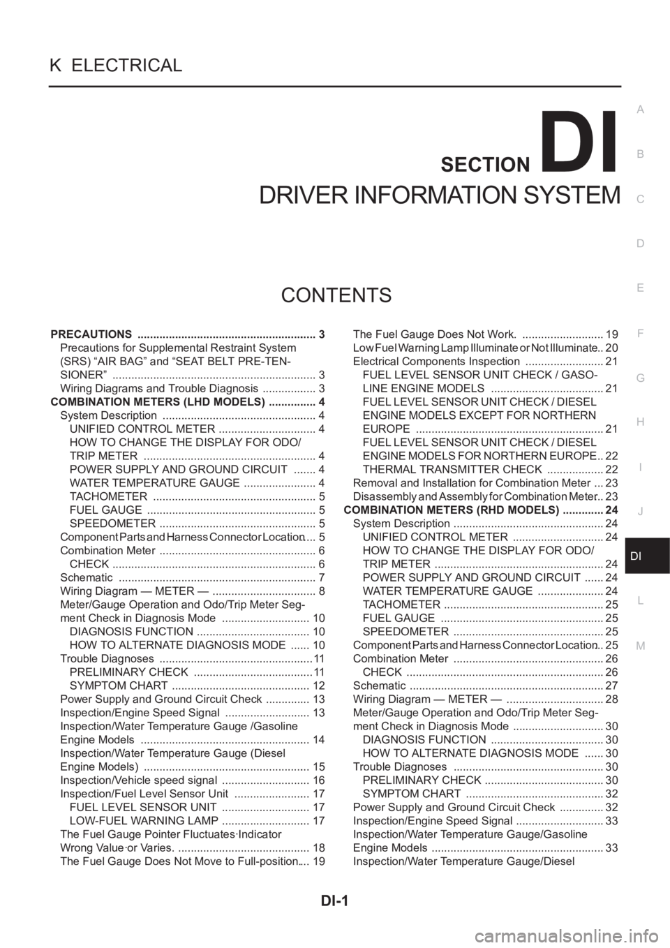
DI-1
DRIVER INFORMATION SYSTEM
K ELECTRICAL
CONTENTS
C
D
E
F
G
H
I
J
L
M
SECTION
A
B
DI
DRIVER INFORMATION SYSTEM
PRECAUTIONS .......................................................... 3
Precautions for Supplemental Restraint System
(SRS) “AIR BAG” and “SEAT BELT PRE-TEN-
SIONER” .................................................................. 3
Wiring Diagrams and Trouble Diagnosis .................. 3
COMBINATION METERS (LHD MODELS) ................ 4
System Description .................................................. 4
UNIFIED CONTROL METER ................................ 4
HOW TO CHANGE THE DISPLAY FOR ODO/
TRIP METER ........................................................ 4
POWER SUPPLY AND GROUND CIRCUIT ........ 4
WATER TEMPERATURE GAUGE ........................ 4
TACHOMETER ..................................................... 5
FUEL GAUGE ....................................................... 5
SPEEDOMETER ................................................... 5
Component Parts and Harness Connector Location ..... 5
Combination Meter ................................................... 6
CHECK .................................................................. 6
Schematic ................................................................ 7
Wiring Diagram — METER — .................................. 8
Meter/Gauge Operation and Odo/Trip Meter Seg-
ment Check in Diagnosis Mode ............................. 10
DIAGNOSIS FUNCTION ..................................... 10
HOW TO ALTERNATE DIAGNOSIS MODE ....... 10
Trouble Diagnoses .................................................. 11
PRELIMINARY CHECK ....................................... 11
SYMPTOM CHART ............................................. 12
Power Supply and Ground Circuit Check ............... 13
Inspection/Engine Speed Signal ............................ 13
Inspection/Water Temperature Gauge /Gasoline
Engine Models ....................................................... 14
Inspection/Water Temperature Gauge (Diesel
Engine Models) ...................................................... 15
Inspection/Vehicle speed signal ............................. 16
Inspection/Fuel Level Sensor Unit ......................... 17
FUEL LEVEL SENSOR UNIT ............................. 17
LOW-FUEL WARNING LAMP ............................. 17
The Fuel Gauge Pointer Fluctuates·Indicator
Wrong Value·or Varies. ........................................... 18
The Fuel Gauge Does Not Move to Full-position. ... 19The Fuel Gauge Does Not Work. ........................... 19
Low Fuel Warning Lamp Illuminate or Not Illuminate ... 20
Electrical Components Inspection .......................... 21
FUEL LEVEL SENSOR UNIT CHECK / GASO-
LINE ENGINE MODELS ..................................... 21
FUEL LEVEL SENSOR UNIT CHECK / DIESEL
ENGINE MODELS EXCEPT FOR NORTHERN
EUROPE ............................................................. 21
FUEL LEVEL SENSOR UNIT CHECK / DIESEL
ENGINE MODELS FOR NORTHERN EUROPE ... 22
THERMAL TRANSMITTER CHECK ................... 22
Removal and Installation for Combination Meter .... 23
Disassembly and Assembly for Combination Meter ... 23
COMBINATION METERS (RHD MODELS) .............. 24
System Description ................................................. 24
UNIFIED CONTROL METER ...........................
... 24
HOW TO CHANGE THE DISPLAY FOR ODO/
TRIP METER ....................................................... 24
POWER SUPPLY AND GROUND CIRCUIT ....... 24
WATER TEMPERATURE GAUGE ...................... 24
TACHOMETER .................................................... 25
FUEL GAUGE ..................................................... 25
SPEEDOMETER ................................................. 25
Component Parts and Harness Connector Location ... 25
Combination Meter .............................................. ... 26
CHECK ................................................................ 26
Schematic ............................................................... 27
Wiring Diagram — METER — ................................ 28
Meter/Gauge Operation and Odo/Trip Meter Seg-
ment Check in Diagnosis Mode .............................. 30
DIAGNOSIS FUNCTION ..................................... 30
HOW TO ALTERNATE DIAGNOSIS MODE ....... 30
Trouble Diagnoses ................................................. 30
PRELIMINARY CHECK ....................................... 30
SYMPTOM CHART ............................................. 32
Power Supply and Ground Circuit Check ............... 32
Inspection/Engine Speed Signal ............................. 33
Inspection/Water Temperature Gauge/Gasoline
Engine Models ........................................................ 33
Inspection/Water Temperature Gauge/Diesel
Page 3560 of 3833
DI-2
Engine Models ........................................................ 35
Inspection/Vehicle speed signal ............................. 35
Inspection/Fuel Level Sensor Unit .......................... 37
FUEL LEVEL SENSOR UNIT .............................. 37
LOW-FUEL WARNING LAMP ............................. 37
The Fuel Gauge Pointer Fluctuates·Indicator
Wrong Value·or Varies. ........................................... 38
The Fuel Gauge Does Not Move to Full-position. ... 39
The Fuel Gauge Does Not Work. ........................... 39
Low Fuel Warning Lamp Illuminate or Not Illuminate ... 40
Electrical Components Inspection .......................... 41
FUEL LEVEL SENSOR UNIT CHECK / GASO-
LINE ENGINE MODELS ...................................... 41
FUEL LEVEL SENSOR UNIT CHECK / DIESEL
ENGINE MODELS ............................................... 41
THERMAL TRANSMITTER CHECK ................... 42
Removal and Installation for Combination Meter .... 42
Disassembly and Assembly for Combination Meter ... 42
WARNING LAMPS .................................................... 43
Schematic ............................................................... 43
Wiring Diagram — WARN —/ LHD Models ............ 44Wiring Diagram — WARN — / RHD Models ........... 50
Electrical Components Inspection ........................... 56
FUEL WARNING LAMP OPERATION CHECK ... 56
OIL PRESSURE SWITCH CHECK ...................... 56
DIODE CHECK .................................................... 56
A/T INDICATOR ......................................................... 57
Wiring Diagram — AT/IND — ................................. 57
WARNING CHIME .................................................. ... 58
System Description ................................................. 58
POWER SUPPLY AND GROUND CIRCUIT ....... 58
IGNITION KEY WARNING CHIME ...................... 58
LIGHT WARNING CHIME ................................... 58
SEAT BELT WARNING CHIME ........................... 58
Wiring Diagram — CHIME — ................................. 59
Symptom Chart ....................................................... 61
Power Supply and Ground Circuit Check ............... 62
Lighting Switch Input Signal Check ......................... 63
Key Switch Insert Signal Check .............................. 65
Door Unlock Sensor Check ..................................... 66
Front Door Switch (driver side) Check .................... 68
CLOCK ...................................................................... 70
Wiring Diagram — CLOCK — ................................. 70