Page 604 of 3833
![NISSAN X-TRAIL 2001 Service Repair Manual EC-254
[QR25(WITH EURO-OBD)]
DTC P0500 VSS
Diagnostic Procedure
EBS00M6D
1. CHECK DTC WITH 4WD/ABS CONTROL UNIT
Check DTC with 4WD/ABS control unit.
Refer to BRC-64
.
OK or NG
OK >> GO TO 2.
NG >> Pe NISSAN X-TRAIL 2001 Service Repair Manual EC-254
[QR25(WITH EURO-OBD)]
DTC P0500 VSS
Diagnostic Procedure
EBS00M6D
1. CHECK DTC WITH 4WD/ABS CONTROL UNIT
Check DTC with 4WD/ABS control unit.
Refer to BRC-64
.
OK or NG
OK >> GO TO 2.
NG >> Pe](/manual-img/5/57405/w960_57405-603.png)
EC-254
[QR25(WITH EURO-OBD)]
DTC P0500 VSS
Diagnostic Procedure
EBS00M6D
1. CHECK DTC WITH 4WD/ABS CONTROL UNIT
Check DTC with 4WD/ABS control unit.
Refer to BRC-64
.
OK or NG
OK >> GO TO 2.
NG >> Perform trouble shooting relevant to DTC indicated.
2. CHECK COMBINATION METER
Check combination meter function.
Refer to DI-10, "
Meter/Gauge Operation and Odo/Trip Meter Segment Check in Diagnosis Mode" (LHD mod-
els), DI-30, "
Meter/Gauge Operation and Odo/Trip Meter Segment Check in Diagnosis Mode" (RHD models).
OK or NG
OK >> GO TO 3.
NG >> Perform trouble shooting relevant to combination meter.
3. CHECK INPUT SIGNAL CIRCUIT
1. Turn ignition switch “OFF”.
2. Disconnect ECM harness connector and combination meter harness connector.
3. Check harness continuity between ECM terminal 81 and combination meter terminal 49 (LHD models), 62
(RHD models).
Refer to wiring diagram.
4. Also check harness for short to ground and short to power.
OK or NG
OK >> GO TO 5.
NG >> GO TO 4.
4. DETECT MALFUNCTIONING PART
Check the following.
●Harness connectors M62, F42
●Harness for open or short between ECM and combination meter
>> Repair harness or connectors.
5. CHECK INTERMITTENT INCIDENT
Perform EC-115, "
TROUBLE DIAGNOSIS FOR INTERMITTENT INCIDENT" .
>>INSPECTION END Continuity should exist.
Page 917 of 3833
![NISSAN X-TRAIL 2001 Service Repair Manual DTC P0500 VSS
EC-567
[QR25(WITHOUT EURO-OBD)]
C
D
E
F
G
H
I
J
K
L
MA
EC
Diagnostic ProcedureEBS00NGX
1.CHECK DTC WITH 4WD/ABS CONTROL UNIT
Check DTC with 4WD/ABS control unit.
Refer to BRC-64
.
OK or NISSAN X-TRAIL 2001 Service Repair Manual DTC P0500 VSS
EC-567
[QR25(WITHOUT EURO-OBD)]
C
D
E
F
G
H
I
J
K
L
MA
EC
Diagnostic ProcedureEBS00NGX
1.CHECK DTC WITH 4WD/ABS CONTROL UNIT
Check DTC with 4WD/ABS control unit.
Refer to BRC-64
.
OK or](/manual-img/5/57405/w960_57405-916.png)
DTC P0500 VSS
EC-567
[QR25(WITHOUT EURO-OBD)]
C
D
E
F
G
H
I
J
K
L
MA
EC
Diagnostic ProcedureEBS00NGX
1.CHECK DTC WITH 4WD/ABS CONTROL UNIT
Check DTC with 4WD/ABS control unit.
Refer to BRC-64
.
OK or NG
OK >> GO TO 2.
NG >> Perform trouble shooting relevant to DTC indicated.
2.CHECK COMBINATION METER
Check combination meter function.
Refer to DI-10, "
Meter/Gauge Operation and Odo/Trip Meter Segment Check in Diagnosis Mode" (LHD mod-
els), DI-30, "
Meter/Gauge Operation and Odo/Trip Meter Segment Check in Diagnosis Mode" (RHD models).
OK or NG
OK >> GO TO 3.
NG >> Perform trouble shooting relevant to combination meter.
3.CHECK INPUT SIGNAL CIRCUIT
1. Turn ignition switch “OFF”.
2. Disconnect ECM harness connector and combination meter harness connector.
3. Check harness continuity between ECM terminal 81 and combination meter terminal 49 (LHD models), 62
(RHD models).
Refer to wiring diagram.
4. Also check harness for short to ground and short to power.
OK or NG
OK >> GO TO 5.
NG >> GO TO 4.
4.DETECT MALFUNCTIONING PART
Check the following.
●Harness connectors M62, F42
●Harness for open or short between ECM and combination meter
>> Repair harness or connectors.
5.CHECK INTERMITTENT INCIDENT
Perform EC-115, "
TROUBLE DIAGNOSIS FOR INTERMITTENT INCIDENT" .
>>INSPECTION END Continuity should exist.
Page 1332 of 3833
![NISSAN X-TRAIL 2001 Service Repair Manual EC-982
[QR20(WITH EURO-OBD)]
DTC P0500 VSS
Diagnostic Procedure
EBS00MY8
1. CHECK DTC WITH ESP/TCS/ABS CONTROL UNIT, 4WD/ABS CONTROL UNIT
Check DTC with ESP/TCS/ABS control unit (with ESP models), 4WD NISSAN X-TRAIL 2001 Service Repair Manual EC-982
[QR20(WITH EURO-OBD)]
DTC P0500 VSS
Diagnostic Procedure
EBS00MY8
1. CHECK DTC WITH ESP/TCS/ABS CONTROL UNIT, 4WD/ABS CONTROL UNIT
Check DTC with ESP/TCS/ABS control unit (with ESP models), 4WD](/manual-img/5/57405/w960_57405-1331.png)
EC-982
[QR20(WITH EURO-OBD)]
DTC P0500 VSS
Diagnostic Procedure
EBS00MY8
1. CHECK DTC WITH ESP/TCS/ABS CONTROL UNIT, 4WD/ABS CONTROL UNIT
Check DTC with ESP/TCS/ABS control unit (with ESP models), 4WD/ABS control unit (without ESP models).
Refer to BRC-64
or BRC-7 .
OK or NG
OK >> GO TO 2.
NG >> Perform trouble shooting relevant to DTC indicated.
2. CHECK COMBINATION METER
Check combination meter function.
Refer to DI-10, "
Meter/Gauge Operation and Odo/Trip Meter Segment Check in Diagnosis Mode" (LHD mod-
els), DI-30, "
Meter/Gauge Operation and Odo/Trip Meter Segment Check in Diagnosis Mode" (RHD models).
OK or NG
OK >> GO TO 3.
NG >> Perform trouble shooting relevant to combination meter.
3. CHECK INPUT SIGNAL CIRCUIT
1. Turn ignition switch “OFF”.
2. Disconnect ECM harness connector and combination meter harness connector.
3. Check harness continuity between ECM terminal 81 and combination meter terminal 49 (LHD models), 62
(RHD models).
Refer to wiring diagram.
4. Also check harness for short to ground and short to power.
OK or NG
OK >> GO TO 5.
NG >> GO TO 4.
4. DETECT MALFUNCTIONING PART
Check the following.
●Harness connectors M62, F42
●Harness for open or short between ECM and combination meter
>> Repair harness or connectors.
5. CHECK INTERMITTENT INCIDENT
Perform EC-847, "
TROUBLE DIAGNOSIS FOR INTERMITTENT INCIDENT" .
>>INSPECTION END Continuity should exist.
Page 1606 of 3833
![NISSAN X-TRAIL 2001 Service Repair Manual EC-1256
[QR20(WITHOUT EURO-OBD)]
DTC P0500 VSS
Diagnostic Procedure
EBS00N6P
1. CHECK DTC WITH ESP/TCS/ABS CONTROL UNIT, 4WD/ABS CONTROL UNIT
Check DTC with ESP/TCS/ABS control unit (with ESP models), NISSAN X-TRAIL 2001 Service Repair Manual EC-1256
[QR20(WITHOUT EURO-OBD)]
DTC P0500 VSS
Diagnostic Procedure
EBS00N6P
1. CHECK DTC WITH ESP/TCS/ABS CONTROL UNIT, 4WD/ABS CONTROL UNIT
Check DTC with ESP/TCS/ABS control unit (with ESP models),](/manual-img/5/57405/w960_57405-1605.png)
EC-1256
[QR20(WITHOUT EURO-OBD)]
DTC P0500 VSS
Diagnostic Procedure
EBS00N6P
1. CHECK DTC WITH ESP/TCS/ABS CONTROL UNIT, 4WD/ABS CONTROL UNIT
Check DTC with ESP/TCS/ABS control unit (with ESP models), 4WD/ABS control unit (without ESP models).
Refer to BRC-64
or BRC-7 .
OK or NG
OK >> GO TO 2.
NG >> Perform trouble shooting relevant to DTC indicated.
2. CHECK COMBINATION METER
Check combination meter function.
Refer to DI-10, "
Meter/Gauge Operation and Odo/Trip Meter Segment Check in Diagnosis Mode" (LHD mod-
els), DI-30, "
Meter/Gauge Operation and Odo/Trip Meter Segment Check in Diagnosis Mode" (RHD models).
OK or NG
OK >> GO TO 3.
NG >> Perform trouble shooting relevant to combination meter.
3. CHECK INPUT SIGNAL CIRCUIT
1. Turn ignition switch "OFF".
2. Disconnect ECM harness connector and combination meter harness connector.
3. Check harness continuity between ECM terminal 81 and combination meter terminal 49 (LHD models), 62
(RHD models).
Refer to wiring diagram.
4. Also check harness for short to ground and short to power.
OK or NG
OK >> GO TO 5.
NG >> GO TO 4.
4. DETECT MALFUNCTIONING PART
Check the following.
●Harness connectors M62, F42
●Harness for open or short between ECM and combination meter
>> Repair harness or connectors.
5. CHECK INTERMITTENT INCIDENT
Perform EC-1192, "
TROUBLE DIAGNOSIS FOR INTERMITTENT INCIDENT" .
>>INSPECTION END Continuity should exist.
Page 2288 of 3833
AT-210
[EURO-OBD]
TROUBLE DIAGNOSES FOR SYMPTOMS
3. CHECK LAMP CIRCUIT
1. Turn ignition switch to “OFF” position.
2. Check resistance between TCM terminals 13 and 10, 19.
3. Reinstall any part removed.
OK or NG
OK >> GO TO 4.
NG >> Check the following items:
●O/D OFF indicator lamp.
Refer to DI-10, "
Meter/Gauge Operation and Odo/Trip
Meter Segment Check in Diagnosis Mode" .
●Harness and fuse for short or open between ignition
switch and O/D OFF indicator lamp
Refer to PG-2, "
POWER SUPPLY ROUTING" .
●Harness for short or open between O/D OFF indicator lamp and TCM.
4. CHECK SYMPTOM
Check again.
OK or NG
OK >>INSPECTION END
NG >> 1. Perform TCM input/output signal inspection.
2. If NG, recheck TCM pin terminals for damage or loose connection with harness connector. Resistance: 50 - 100Ω
SCIA0767E
Page 2391 of 3833
TROUBLE DIAGNOSES FOR SYMPTOMS
AT-313
[EXC.F/EURO-OBD]
D
E
F
G
H
I
J
K
L
MA
B
AT
3.CHECK LAMP CIRCUIT
1. Turn ignition switch to “OFF” position.
2. Check resistance between TCM terminals 13 and 10, 19.
3. Reinstall any part removed.
OK or NG
OK >> GO TO 4.
NG >> Check the following items:
●O/D OFF indicator lamp.
Refer to DI-10, "
Meter/Gauge Operation and Odo/Trip
Meter Segment Check in Diagnosis Mode" .
●Harness and fuse for short or open between ignition
switch and O/D OFF indicator lamp
Refer to PG-2, "
POWER SUPPLY ROUTING" .
●Harness for short or open between O/D OFF indicator lamp and TCM.
4.CHECK SYMPTOM
Check again.
OK or NG
OK >>INSPECTION END
NG >> 1. Perform TCM input/output signal inspection.
2. If NG, recheck TCM pin terminals for damage or loose connection with harness connector. Resistance: 50 - 100Ω
SCIA0767E
Page 3568 of 3833

DI-10
COMBINATION METERS (LHD MODELS)
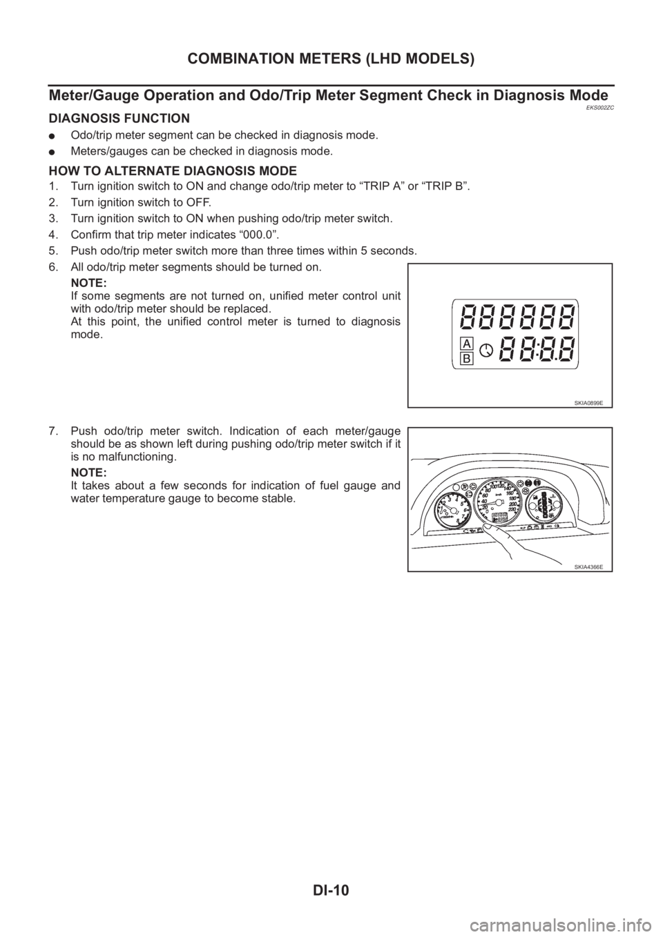
Meter/Gauge Operation and Odo/Trip Meter Segment Check in Diagnosis Mode
EKS002ZC
DIAGNOSIS FUNCTION
●Odo/trip meter segment can be checked in diagnosis mode.
●Meters/gauges can be checked in diagnosis mode.
HOW TO ALTERNATE DIAGNOSIS MODE
1. Turn ignition switch to ON and change odo/trip meter to “TRIP A” or “TRIP B”.
2. Turn ignition switch to OFF.
3. Turn ignition switch to ON when pushing odo/trip meter switch.
4. Confirm that trip meter indicates “000.0”.
5. Push odo/trip meter switch more than three times within 5 seconds.
6. All odo/trip meter segments should be turned on.
NOTE:
If some segments are not turned on, unified meter control unit
with odo/trip meter should be replaced.
At this point, the unified control meter is turned to diagnosis
mode.
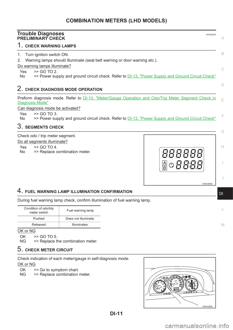
7. Push odo/trip meter switch. Indication of each meter/gauge
should be as shown left during pushing odo/trip meter switch if it
is no malfunctioning.
NOTE:
It takes about a few seconds for indication of fuel gauge and
water temperature gauge to become stable.
SKIA0899E
SKIA4366E
Page 3569 of 3833

COMBINATION METERS (LHD MODELS)
DI-11
C
D
E
F
G
H
I
J
L
MA
B
DI
Trouble DiagnosesEKS002ZD
PRELIMINARY CHECK
1.CHECK WARNING LAMPS
1. Turn ignition switch ON.
2. Warning lamps should illuminate (seat belt warning or door warning etc.).
Do warning lamps illuminate?
Ye s > > G O T O 2 .
No >> Power supply and ground circuit check. Refer to DI-13, "
Power Supply and Ground Circuit Check"
.
2.CHECK DIAGNOSIS MODE OPERATION
Preform diagnosis mode. Refer to DI-10, "
Meter/Gauge Operation and Odo/Trip Meter Segment Check in
Diagnosis Mode" .
Can diagnosis mode be activated?
Ye s > > G O T O 3 .
No >> Power supply and ground circuit check. Refer to DI-13, "
Power Supply and Ground Circuit Check"
3.SEGMENTS CHECK
Check odo / trip meter segment.
Do all segments illuminate?
Ye s > > G O T O 4 .
No >> Replace combination meter.
4.FUEL WARNING LAMP ILLUMINATION CONFIRMATION
During fuel warning lamp check, confirm illumination of fuel warning lamp.
OK or NG
OK >> GO TO 5.
NG >> Replace the combination meter.
5.CHECK METER CIRCUIT
Check indication of each meter/gauge in self-diagnosis mode.
OK or NG
OK >> Go to symptom chart.
NG >> Replace combination meter.
SKIA0899E
Condition of odo/trip
meter switchFuel warning lamp
Pushed Does not illuminate.
Released Illuminates.
SKIA4366E