2001 NISSAN X-TRAIL belt
[x] Cancel search: beltPage 3044 of 3833
SRS-42
DISPOSAL OF AIR BAG MODULE AND SEAT BELT PRE-TENSIONER
Air Bag Deployment Tool Lamp Illumination Chart (Battery Connected)
*: If this lamp glows red, the tool is connected to the battery incorrectly. Reverse the connections and make sure the lamp glows green.
DEPLOYMENT PROCEDURES FOR AIR BAG MODULE (OUTSIDE OF VEHICLE)
Unless the vehicle is being scrapped, deploying the air bag in the
vehicle is not recommended. This may cause damage to the vehicle
interior.
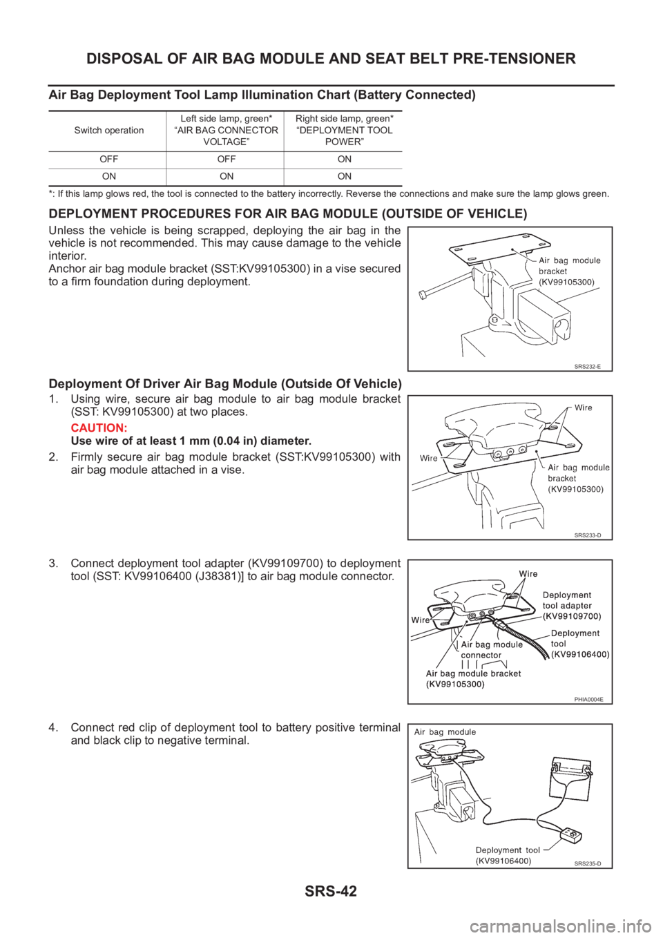
Anchor air bag module bracket (SST:KV99105300) in a vise secured
to a firm foundation during deployment.
Deployment Of Driver Air Bag Module (Outside Of Vehicle)
1. Using wire, secure air bag module to air bag module bracket
(SST: KV99105300) at two places.
CAUTION:
Use wire of at least 1 mm (0.04 in) diameter.
2. Firmly secure air bag module bracket (SST:KV99105300) with
air bag module attached in a vise.
3. Connect deployment tool adapter (KV99109700) to deployment
tool (SST: KV99106400 (J38381)] to air bag module connector.
4. Connect red clip of deployment tool to battery positive terminal
and black clip to negative terminal.
Switch operationLeft side lamp, green*
“AIR BAG CONNECTOR
VOLTAGE”Right side lamp, green*
“DEPLOYMENT TOOL
POWER”
OFF OFF ON
ON ON ON
SRS232-E
SRS233-D
PHIA0004E
SRS235-D
Page 3045 of 3833
DISPOSAL OF AIR BAG MODULE AND SEAT BELT PRE-TENSIONER
SRS-43
C
D
E
F
G
I
J
K
L
MA
B
SRS
5. The lamp on the right side of the tool, marked “deployment tool power”, should glow green, not red.
6. Press the button on the deployment tool. The left side lamp on the tool, marked “air bag connector volt-
age”, will illuminate and the air bag module will deploy.
CAUTION:
When deploying the driver air bag module, stand at least 5 m (16 ft) away from the air bag module.
Deployment Of Front Passenger Air Bag Module (Outside Of Vehicle)
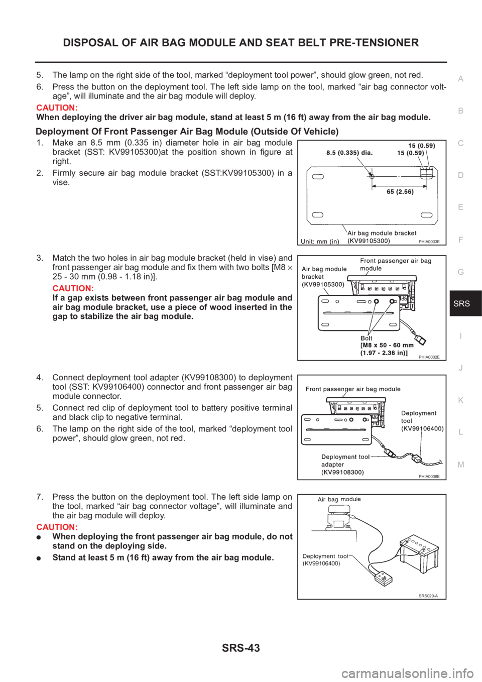
1. Make an 8.5 mm (0.335 in) diameter hole in air bag module
bracket (SST: KV99105300)at the position shown in figure at
right.
2. Firmly secure air bag module bracket (SST:KV99105300) in a
vise.
3. Match the two holes in air bag module bracket (held in vise) and
front passenger air bag module and fix them with two bolts [M8 ×
25 - 30 mm (0.98 - 1.18 in)].
CAUTION:
If a gap exists between front passenger air bag module and
air bag module bracket, use a piece of wood inserted in the
gap to stabilize the air bag module.
4. Connect deployment tool adapter (KV99108300) to deployment
tool (SST: KV99106400) connector and front passenger air bag
module connector.
5. Connect red clip of deployment tool to battery positive terminal
and black clip to negative terminal.
6. The lamp on the right side of the tool, marked “deployment tool
power”, should glow green, not red.
7. Press the button on the deployment tool. The left side lamp on
the tool, marked “air bag connector voltage”, will illuminate and
the air bag module will deploy.
CAUTION:
●When deploying the front passenger air bag module, do not
stand on the deploying side.
●Stand at least 5 m (16 ft) away from the air bag module.
PHIA0033E
PHIA0032E
PHIA0038E
SRS020-A
Page 3046 of 3833
SRS-44
DISPOSAL OF AIR BAG MODULE AND SEAT BELT PRE-TENSIONER
Deployment Of Front Side Air Bag Module (Outside Of Vehicle)
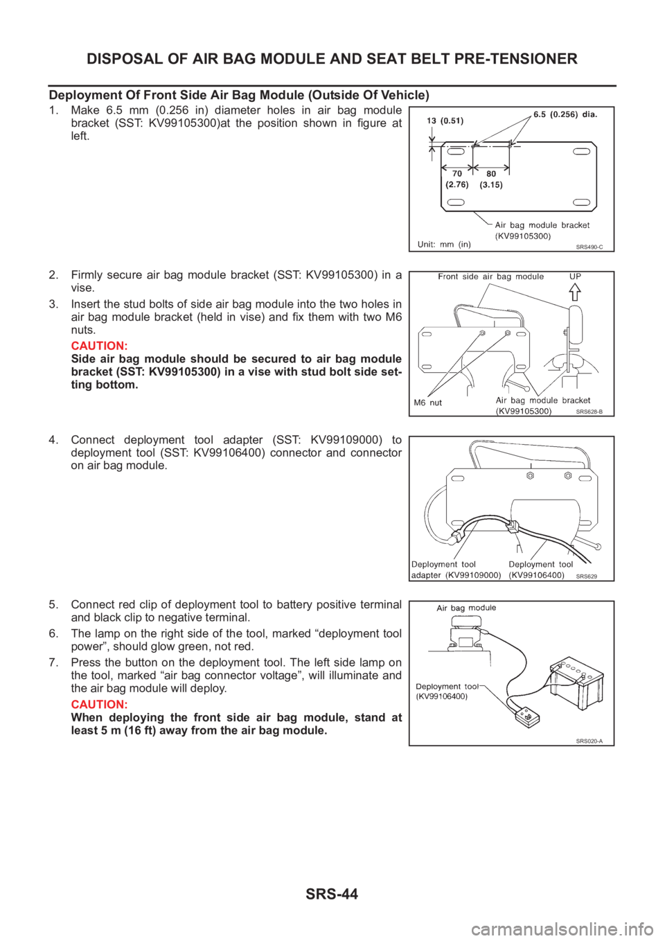
1. Make 6.5 mm (0.256 in) diameter holes in air bag module
bracket (SST: KV99105300)at the position shown in figure at
left.
2. Firmly secure air bag module bracket (SST: KV99105300) in a
vise.
3. Insert the stud bolts of side air bag module into the two holes in
air bag module bracket (held in vise) and fix them with two M6
nuts.
CAUTION:
Side air bag module should be secured to air bag module
bracket (SST: KV99105300) in a vise with stud bolt side set-
ting bottom.
4. Connect deployment tool adapter (SST: KV99109000) to
deployment tool (SST: KV99106400) connector and connector
on air bag module.
5. Connect red clip of deployment tool to battery positive terminal
and black clip to negative terminal.
6. The lamp on the right side of the tool, marked “deployment tool
power”, should glow green, not red.
7. Press the button on the deployment tool. The left side lamp on
the tool, marked “air bag connector voltage”, will illuminate and
the air bag module will deploy.
CAUTION:
When deploying the front side air bag module, stand at
least 5 m (16 ft) away from the air bag module.
SRS490-C
SRS628-B
SRS629
SRS020-A
Page 3047 of 3833
DISPOSAL OF AIR BAG MODULE AND SEAT BELT PRE-TENSIONER
SRS-45
C
D
E
F
G
I
J
K
L
MA
B
SRS
DEPLOYMENT PROCEDURES FOR SEAT BELT PRE-TENSIONER (OUTSIDE OF VEHICLE)
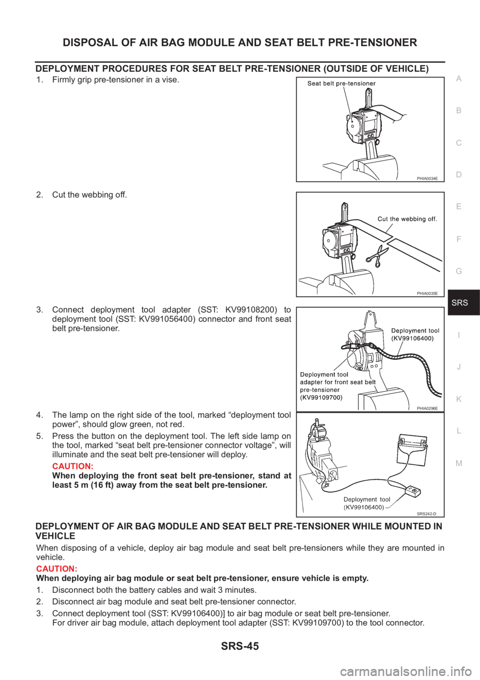
1. Firmly grip pre-tensioner in a vise.
2. Cut the webbing off.
3. Connect deployment tool adapter (SST: KV99108200) to
deployment tool (SST: KV991056400) connector and front seat
belt pre-tensioner.
4. The lamp on the right side of the tool, marked “deployment tool
power”, should glow green, not red.
5. Press the button on the deployment tool. The left side lamp on
the tool, marked “seat belt pre-tensioner connector voltage”, will
illuminate and the seat belt pre-tensioner will deploy.
CAUTION:
When deploying the front seat belt pre-tensioner, stand at
least 5 m (16 ft) away from the seat belt pre-tensioner.
DEPLOYMENT OF AIR BAG MODULE AND SEAT BELT PRE-TENSIONER WHILE MOUNTED IN
VEHICLE
When disposing of a vehicle, deploy air bag module and seat belt pre-tensioners while they are mounted in
vehicle.
CAUTION:
When deploying air bag module or seat belt pre-tensioner, ensure vehicle is empty.
1. Disconnect both the battery cables and wait 3 minutes.
2. Disconnect air bag module and seat belt pre-tensioner connector.
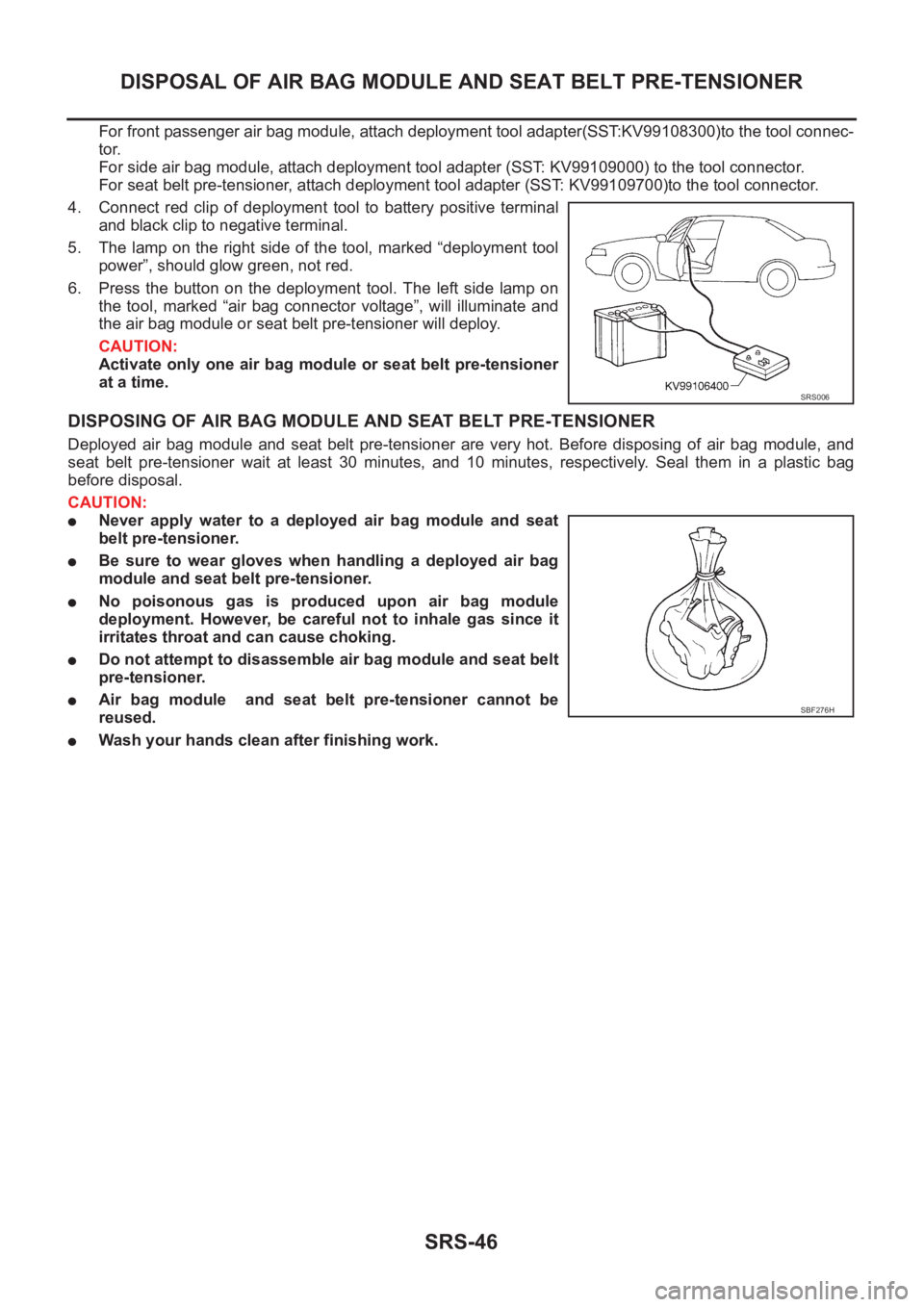
3. Connect deployment tool (SST: KV99106400)] to air bag module or seat belt pre-tensioner.
For driver air bag module, attach deployment tool adapter (SST: KV99109700) to the tool connector.
PHIA0034E
PHIA0035E
PHIA0296E
SRS242-D
Page 3048 of 3833
SRS-46
DISPOSAL OF AIR BAG MODULE AND SEAT BELT PRE-TENSIONER
For front passenger air bag module, attach deployment tool adapter(SST:KV99108300)to the tool connec-
tor.
For side air bag module, attach deployment tool adapter (SST: KV99109000) to the tool connector.
For seat belt pre-tensioner, attach deployment tool adapter (SST: KV99109700)to the tool connector.
4. Connect red clip of deployment tool to battery positive terminal
and black clip to negative terminal.
5. The lamp on the right side of the tool, marked “deployment tool
power”, should glow green, not red.
6. Press the button on the deployment tool. The left side lamp on
the tool, marked “air bag connector voltage”, will illuminate and
the air bag module or seat belt pre-tensioner will deploy.
CAUTION:
Activate only one air bag module or seat belt pre-tensioner
at a time.
DISPOSING OF AIR BAG MODULE AND SEAT BELT PRE-TENSIONER
Deployed air bag module and seat belt pre-tensioner are very hot. Before disposing of air bag module, and
seat belt pre-tensioner wait at least 30 minutes, and 10 minutes, respectively. Seal them in a plastic bag
before disposal.
CAUTION:
●Never apply water to a deployed air bag module and seat
belt pre-tensioner.
●Be sure to wear gloves when handling a deployed air bag
module and seat belt pre-tensioner.
●No poisonous gas is produced upon air bag module
deployment. However, be careful not to inhale gas since it
irritates throat and can cause choking.
●Do not attempt to disassemble air bag module and seat belt
pre-tensioner.
●Air bag module and seat belt pre-tensioner cannot be
reused.
●Wash your hands clean after finishing work.
SRS006
SBF276H
Page 3049 of 3833
COLLISION DIAGNOSIS
SRS-47
C
D
E
F
G
I
J
K
L
MA
B
SRS
COLLISION DIAGNOSISPFP:00015
For Frontal CollisionEHS000DF
To repair the SRS, perform the following steps.
WHEN SRS (EXCEPT THE FRONT SIDE AIR BAG) IS ACTIVATED IN A COLLISION:
1. Replace the diagnosis sensor unit.
2. Remove the air bag modules (except the front side air bag module), bracket and seat belt pre-tensioner
assemblies.
3. Check the SRS components using the table shown below:
–Replace any SRS components showing visible signs of damage (dents, cracks and deformation).
4. Install new air bag modules (except the front side air bag module) and seat belt pre-tensioner assemblies.
5. Conduct self-diagnosis using CONSULT-II or “AIR BAG” warning lamp. Refer to SRS-16, "
SRS Operation
Check" for details. Ensure entire SRS operation properly.
WHEN SRS IS NOT ACTIVATED IN A COLLISION:
1. Check the SRS components using the table shown below:
–Replace any SRS components showing visible signs of damage (dents, cracks and deformation).
2. Conduct self-diagnosis using CONSULT-II or “AIR BAG” warning lamp. Refer to SRS-16, "
SRS Operation
Check" for details. Ensure entire SRS operation properly.
SRS INSPECTION (FOR FRONTAL COLLISION)
Part SRS is activated SRS is NOT activated
Air bag module
(driver or front pas-
senger air bag mod-
ule)REPLACE
Install with new bolts.1. Remove air bag module. Check harness cover and connectors for damage, termi-
nals for deformities, and harness for binding.
2.
–Install driver air bag module into the steering wheel to check fit and alignment with
the wheel.
–Install passenger air bag module into the instrument panel to check fit with the
instrument panel.
3. No damage found, reinstall with new bolts.
4. If damaged—REPLACE. Install air bag modules with new special bolts
Air bag must be deployed before discarding.
Seat belt pre-ten-
sioner assemblyREPLACE
Install seat belt pre-
tensioner with new
bolts.1. Remove seat belt pre-tensioners.
Check harness cover and connectors for damage, terminals for deformities, and
harness for binding.
2. Check belts for damage and anchors for loose mounting.
3. Check retractor for smooth operation.
4. If no damage is found, reinstall seat belt pre-tensioner assembly.
5. If damaged—REPLACE. Install the seat belt pre-tensioners with new bolts.
Seat belt pre-tensioners must be deployed before discarding.
Diagnosis sensor unit REPLACE
Install with new bolts.1. Check case for dents, cracks or deformities.
2. Check connectors for damage, and terminals for deformities.
3. If no damage is found, reinstall with new bolts and ground bolt.
4. If damaged—REPLACE. Install diagnosis sensor unit with new bolts and ground
bolt.
Steering wheel 1. Visually check steering wheel for deformities.
2. Check harness (built into steering wheel) and connectors for damage, and terminals for deformities.
3. Install air bag module to check fit or alignment with steering wheel.
4. Check steering wheel for excessive free play.
5. If no damage is found, reinstall with bolts.
6. If damaged—REPLACE.
Page 3051 of 3833
COLLISION DIAGNOSIS
SRS-49
C
D
E
F
G
I
J
K
L
MA
B
SRS
SRS INSPECTION (FOR SIDE COLLISION)
PartFront side air bag and
side curtain air bag is
activatedFront side air bag and side curtain air bag is NOT activated
Front LH or RH side
air bag moduleREPLACE all parts of
seat back with
deployed front side
air bag module.1. Check for visible signs of damage (dents, tears, deformation) of the seat back on
the collision side.
2. If damaged—REPLACE the damaged seat parts with new bolts and remove the
front side air bag module.
3. Check for visible signs of damaged (tears etc.) of the front LH or RH side air bag
module.
4. Check harness and connectors for damage, and terminals for deformities.
5. If no damaged is found, reinstall the front LH or RH side air bag module with new
nuts.
6. If damaged—REPLACE the front LH or RH side air bag module with new nut.
Air bag must be deployed before disposing of it.
LH or RH side air bag
(Satellite) sensor REPLACE the side
air bag (Satellite)
sensor on the colli-
sion side with new
nuts.
(Repair the center pil-
lar inner, etc. before
installing new one if
damaged.)1. Remove the LH or RH side air bag (Satellite) sensor on the collision side. Check
harness connectors for damage, terminals for deformities, and harness for binding.
2. Check for visible signs of damage (dents, cracks, deformation) of the LH or RH
side air bag (Satellite) sensor.
3. Install the LH or RH side air bag (Satellite) sensor to check fit.
4. If no damage is found, reinstall the LH or RH side sir bag (Satellite) sensor with
new nuts.
5. If damaged—REPLACE the LH or RH side air bag (Satellite) sensor with new
nuts.
Diagnosis sensor unit REPLACE the diag-
nosis sensor unit with
the new bolts.1. Check case and bracket for dents, cracks or deformities.
2. Check connectors for damage, and terminals for deformities.
3. If no damage is found, reinstall the diagnosis sensor unit with new bolts and
ground bolt.
4. If damaged—REPLACE the diagnosis sensor unit with new bolts and ground bolt.
Seat belt pre-ten-
sioner assembly1. Check if the seat belt can be extended smoothly.
If the seat belt cannot be extended smoothly,
–Check for deformities of the center pillar inner.
–If the center pillar inner has no damage, REPLACE the seat belt pre-tensioner assembly.
2. Remove the seat belt pre-tensioner assembly on the collision side. Check harness cover and connectors
for damage, terminals for deformities, and harness for binding.
3. Check for visible signs of damage (dents, cracks, deformation) of the seat belt pre-tensioner assembly.
4. If no damage is found, reinstall the seat belt pre-tensioner assembly.
5. If damaged—REPLACE the seat belt pre-tensioner assembly with new bolts.
The seat belt pre-tensioner assembly must be deployed before disposing of it.
Seat with front side
air bagREPLACE all parts of
front seat back
(including front seat
back frame)1. Visually check the seat on the collision side.
2. Remove the seat on the collision side and check the following for damage and
deformities.
–Harness, connectors and terminals
–Frame and recliner (for front and rear seat), and also adjuster and slides (for front
seat)
3. If no damage is found, reinstall the seat.
4. If damaged—REPLACE the damaged seat parts with new bolts.
Center pillar inner 1. Check the center pillar inner on the collision side for damage (dents, cracks, deformation).
2. If damaged—REPAIR the center pillar inner.
Trim 1. Check for visible signs of damage (dents, cracks, deformation) of the interior trim on the collision side.
2. If damaged—REPLACE the damaged trim parts.
Page 3053 of 3833

BL-1
BODY, LOCK & SECURITY SYSTEM
I BODY
CONTENTS
C
D
E
F
G
H
J
K
L
M
SECTION
A
B
BL
BODY, LOCK & SECURITY SYSTEM
PRECAUTIONS .......................................................... 3
Precautions for Supplemental Restraint System
(SRS) “AIR BAG” and “SEAT BELT PRE-TEN-
SIONER” .................................................................. 3
Precautions .............................................................. 3
HOOD ......................................................................... 4
Fitting Adjustment .................................................... 4
FRONT END HEIGHT ADJUSTMENT AND LAT-
ERAL/LONGITUDINAL CLEARANCE ADJUST-
MENT .................................................................... 4
SURFACE HEIGHT ADJUSTMENT ..................... 4
Removal and Installation of Hood Assembly ............ 5
Removal and Installation of Hood Lock Control ....... 6
REMOVAL ............................................................. 6
INSTALLATION ..................................................... 7
Hood Lock Control Inspection .................................. 7
DOOR ......................................................................... 8
Fitting Adjustment .................................................... 8
FRONT DOOR ...................................................... 8
REAR DOOR ........................................................ 8
STRIKER ADJUSTMENT ..................................... 8
Removal and Installation .......................................... 9
Door Weatherstrip .................................................. 10
POWER DOOR LOCK SYSTEM ...............................11
System Description ................................................. 11
OPERATION ........................................................ 11
Component Parts and Harness Connector Location .... 11
Schematic .............................................................. 12
Wiring Diagram — D/LOCK — ............................... 13
Terminal and Reference Value for Time Control Unit ... 17
Symptom Chart ...................................................... 18
Power Supply and Ground Circuit Check ............... 18
Door Lock/Unlock Switch Check ............................ 19
Door Key Cylinder Switch Check ........................... 20
Front Door Lock Actuator (Driver Side) Check ....... 21
Front Door Lock Actuator (Passenger Side) Check ... 22
Rear Door Lock Actuator LH Check ....................... 23
Rear Door Lock Actuator RH Check ...................... 24
Back Door Lock Actuator Check ............................ 25
Door Switch Check ................................................. 26Door Unlock Sensor Check .................................... 26
Key Switch Check ................................................... 27
POWER DOOR LOCK — SUPER LOCK — ............ 29
System Description ................................................. 29
OUTLINE ............................................................. 29
OPERATION .....................................................
... 29
Schematic ............................................................... 31
Wiring Diagram — S/LOCK — ............................... 32
Terminal and Reference Value for Time Control Unit ... 38
Trouble Diagnoses ................................................. 39
PRELIMINARY CHECK ....................................... 39
SYMPTOM CHART ............................................. 40
Power Supply and Ground Circuit Check ............... 41
Door Lock/Unlock Switch Check ............................ 42
Door Key Cylinder Switch Check ............................ 43
Front Door Lock Actuator (Driver Side) Check ....... 44
Front Door Lock Actuator (Passenger Side) Check ... 45
Rear Door Lock Actuator LH Check ....................... 46
Rear Door Lock Actuator RH Check ....................... 47
Back Door Lock Actuator Check ............................. 48
Door Switch Check ................................................. 49
Door Unlock Sensor Check .................................... 50
Key Switch Check ................................................... 51
Super Lock Actuator Check .................................... 52
NATS Release Signal Check .................................. 53
Ignition Switch “ON” Circuit Check ......................... 54
MULTI-REMOTE CONTROL SYSTEM ..................... 55
Component Parts and Harness Connector Location ... 55
System Description ................................................. 56
FUNCTION .......................................................... 56
LOCK OPERATION ............................................. 56
UNLOCK OPERATION ........................................ 56
HAZARD REMINDER ......................................... 56
MULTI-REMOTE CONTROLLER ID CODE
ENTRY ................................................................ 56
Wiring Diagram — MULTI — .................................. 57
Terminal and Reference Value for Multi-remote
Control Unit ............................................................. 59
Symptom Chart ....................................................... 59
Remote Controller Battery Check ........................... 59