Page 528 of 1306

Component Description
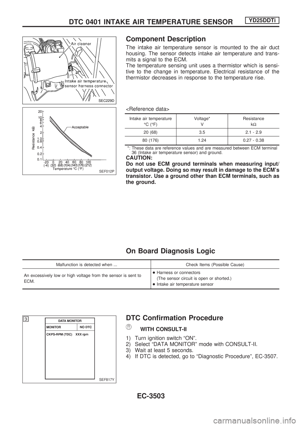
The intake air temperature sensor is mounted to the air duct
housing. The sensor detects intake air temperature and trans-
mits a signal to the ECM.
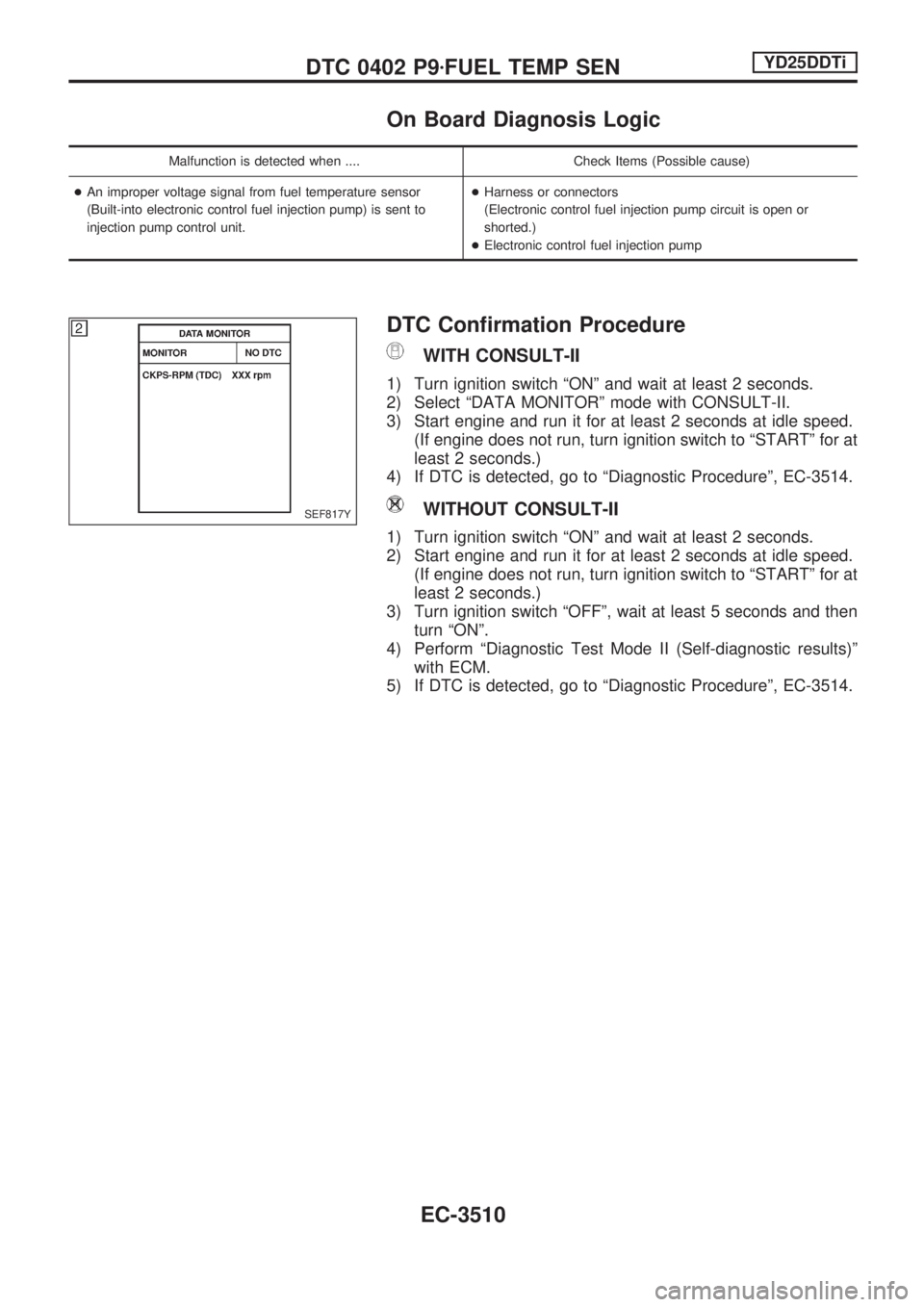
The temperature sensing unit uses a thermistor which is sensi-
tive to the change in temperature. Electrical resistance of the
thermistor decreases in response to the temperature rise.
Intake air temperature
ÉC (ÉF)Voltage*
VResistance
kW
20 (68) 3.5 2.1 - 2.9
80 (176) 1.24 0.27 - 0.38
*: These data are reference values and are measured between ECM terminal
36 (Intake air temperature sensor) and ground.
CAUTION:
Do not use ECM ground terminals when measuring input/
output voltage. Doing so may result in damage to the ECM's
transistor. Use a ground other than ECM terminals, such as
the ground.
On Board Diagnosis Logic
Malfunction is detected when ... Check Items (Possible Cause)
An excessively low or high voltage from the sensor is sent to
ECM.+Harness or connectors
(The sensor circuit is open or shorted.)
+Intake air temperature sensor
DTC Confirmation Procedure
WITH CONSULT-II
1) Turn ignition switch ªONº.
2) Select ªDATA MONITORº mode with CONSULT-II.
3) Wait at least 5 seconds.
4) If DTC is detected, go to ªDiagnostic Procedureº, EC-3507.
SEC229D
SEF012P
SEF817Y
DTC 0401 INTAKE AIR TEMPERATURE SENSORYD25DDTi
EC-3503
Page 535 of 1306

On Board Diagnosis Logic
Malfunction is detected when .... Check Items (Possible cause)
+An improper voltage signal from fuel temperature sensor
(Built-into electronic control fuel injection pump) is sent to
injection pump control unit.+Harness or connectors
(Electronic control fuel injection pump circuit is open or
shorted.)
+Electronic control fuel injection pump
DTC Confirmation Procedure
WITH CONSULT-II
1) Turn ignition switch ªONº and wait at least 2 seconds.
2) Select ªDATA MONITORº mode with CONSULT-II.
3) Start engine and run it for at least 2 seconds at idle speed.
(If engine does not run, turn ignition switch to ªSTARTº for at
least 2 seconds.)
4) If DTC is detected, go to ªDiagnostic Procedureº, EC-3514.
WITHOUT CONSULT-II
1) Turn ignition switch ªONº and wait at least 2 seconds.
2) Start engine and run it for at least 2 seconds at idle speed.
(If engine does not run, turn ignition switch to ªSTARTº for at
least 2 seconds.)
3) Turn ignition switch ªOFFº, wait at least 5 seconds and then
turn ªONº.
4) Perform ªDiagnostic Test Mode II (Self-diagnostic results)º
with ECM.
5) If DTC is detected, go to ªDiagnostic Procedureº, EC-3514.
SEF817Y
DTC 0402 P9zFUEL TEMP SENYD25DDTi
EC-3510
Page 547 of 1306
Diagnostic Procedure
1 CHECK OVERALL FUNCTION-I
With CONSULT-II
1. Turn ignition switch ªONº.
2. Select ªACCEL POS SENº in ªDATA MONITORº mode with CONSULT-II.
3. Check ªACCEL POS SENº signal under the following conditions.
SEF278ZB
Without CONSULT-II
1. Turn ignition switch ªONº.
2. Check voltage between ECM terminal 23 and ground under the following conditions.
SEF279ZB
OK or NG
OKcGO TO 2.
NGcGO TO 3.
DTC 0403 ACCEL POS SENSORYD25DDTi
EC-3522
Page 548 of 1306
2 CHECK OVERALL FUNCTION
With CONSULT-II
1. Turn ignition switch ªONº.
2. Select ªFULL ACCEL SWº and ªOFF ACCEL SWº in ªDATA MONITORº mode with CONSULT-II.
3. Check ªFULL ACCEL SWº and ªOFF ACCEL SWº signal under the following conditions.
SEF416Y
Without CONSULT-II
1. Turn ignition switch ªONº.
2. Check voltage between ECM terminals 31, 32 and ground under the following conditions.
SEF417Y
OK or NG
OKcGO TO 24.
NGcGO TO 15.
DTC 0403 ACCEL POS SENSORYD25DDTi
Diagnostic Procedure (Cont'd)
EC-3523
Page 550 of 1306

5 CHECK ACCELERATOR POSITION SENSOR GROUND CIRCUIT FOR OPEN AND SHORT
1. Turn ignition switch ªOFFº.
2. Loosen and retighten engine ground screw.
SEC245D
3. Check harness continuity between accelerator work unit terminal 3 and engine ground. Refer to Wiring Diagram.
Continuity should exist.
4. Also check harness for short to ground and short to power.
OK or NG
OKcGO TO 7.
NGcGO TO 6.
6 DETECT MALFUNCTIONING PART
Check the following.
+Harness connectors F54, M48 (RHD models)
+Harness for open or short between ECM and accelerator work unit
cRepair open circuit or short to ground or short to power in harness or connectors.
7 CHECK ACCELERATOR POSITION SENSOR INPUT SIGNAL CIRCUIT FOR OPEN AND SHORT
1. Disconnect ECM harness connector.
2. Check harness continuity between ECM terminal 23 and accelerator work unit terminal 2. Refer to Wiring Diagram.
Continuity should exist.
3. Also check harness for short to ground and short to power.
OK or NG
OK (With CONSULT-II)cGO TO 9.
OK (Without CONSULT-II)cGO TO 10.
NGcGO TO 8.
8 DETECT MALFUNCTIONING PART
Check the following.
+Harness connectors F55, M47 (RHD models)
+Harness for open or short between ECM and accelerator work unit
cRepair open circuit or short to ground or short to power in harness or connectors.
DTC 0403 ACCEL POS SENSORYD25DDTi
Diagnostic Procedure (Cont'd)
EC-3525
Page 554 of 1306

17 CHECK ACCELERATOR POSITION SWITCH INPUT SIGNAL CIRCUIT-I FOR OPEN AND SHORT
1. Turn ignition switch ªOFFº.
2. Disconnect ECM harness connector.
3. Check harness continuity between accelerator work unit terminal 6 and ECM terminal 31. Refer to Wiring Diagram.
Continuity should exist.
4. Also check harness for short to ground and short to power.
OK or NG
OKcGO TO 19.
NGcGO TO 18.
18 DETECT MALFUNCTIONING PART
Check the following.
+Harness connectors M47, F55 (RHD models)
+Harness for open or short between ECM and accelerator work unit
cRepair open circuit or short to ground or short to power in harness or connectors.
19 CHECK ACCELERATOR POSITION SWITCH INPUT SIGNAL CIRCUIT-II FOR OPEN AND SHORT
1. Check harness continuity between accelerator work unit terminal 4 and ECM terminal 32. Refer to Wiring Diagram.
Continuity should exist.
2. Also check harness for short to ground and short to power.
OK or NG
OKcGO TO 21.
NGcGO TO 20.
20 DETECT MALFUNCTIONING PART
Check the following.
+Harness connectors M47, F55 (RHD models)
+Harness for open or short between ECM and accelerator work unit
cRepair open circuit or short to ground or short to power in harness or connectors.
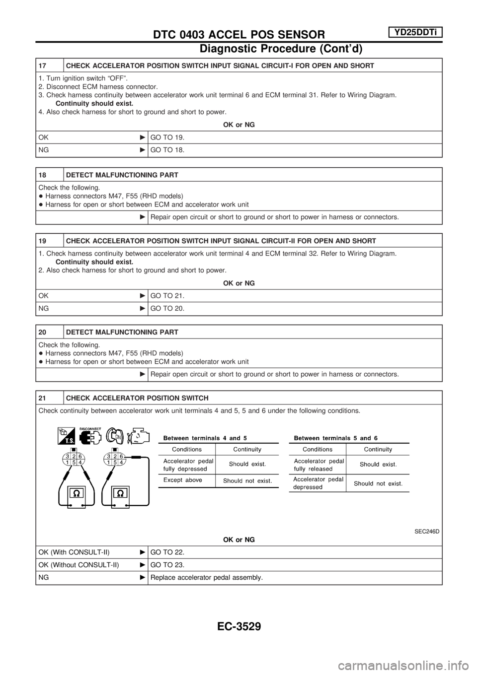
21 CHECK ACCELERATOR POSITION SWITCH
Check continuity between accelerator work unit terminals 4 and 5, 5 and 6 under the following conditions.
SEC246D
OK or NG
OK (With CONSULT-II)cGO TO 22.
OK (Without CONSULT-II)cGO TO 23.
NGcReplace accelerator pedal assembly.
DTC 0403 ACCEL POS SENSORYD25DDTi
Diagnostic Procedure (Cont'd)
EC-3529
Page 560 of 1306

On Board Diagnosis Logic
Malfunction is detected when ... Check Items (Possible Cause)
+An improper signal from the sensor is sent to ECM during
engine running and cranking.+Harness or connectors
(The sensor circuit is open.)
+Crankshaft position sensor (TDC)
DTC Confirmation Procedure
Before performing the following procedure, confirm that
battery voltage is more than 10V.
WITH CONSULT-II
1) Turn ignition switch ªONº and select ªDATA MONITORº
mode with CONSULT-II.
2) Crank engine for at least 1 second.
3) Start engine and run it for at least 2 seconds at idle speed.
4) If DTC is detected, go to ªDiagnostic Procedureº, EC-3538.
WITHOUT CONSULT-II
1) Crank engine for at least 1 second.
2) Start engine and run it for at least 2 seconds at idle speed.
3) Turn ignition switch ªOFFº, wait at least 5 seconds and then
turn ªONº.
4) Perform ªDiagnostic Test Mode II (Self-diagnostic results)º
with ECM.
5) If DTC is detected, go to ªDiagnostic Procedureº, EC-3538.
SEF817Y
DTC 0407 CRANK POS SEN (TDC)YD25DDTi
EC-3535
Page 562 of 1306

Diagnostic Procedure
1 CHECK CRANKSHAFT POSITION SENSOR (TDC) GROUND CIRCUIT FOR OPEN AND SHORT
1. Turn ignition switch ªOFFº.
2. Loosen and retighten engine ground screws.
SEC245D
3. Disconnect crankshaft position sensor (TDC) harness connector and ECM harness connector.
SEC238D
4. Check harness continuity between ECM terminal 47 and crankshaft position sensor (TDC) terminal 2. Refer to Wiring Diagram.
Continuity should exist.
5. Also check harness for short to ground and short to power.
OK or NG
OKcGO TO 2.
NGcGO TO 3.
2 DETECT MALFUNCTIONING PART
Check the following.
+Harness connectors M279, E237 (LHD models)
+Harness connectors F36, E237 (RHD models)
+Harness for open and short between crankshaft position sensor (TDC) and ECM
cRepair harness or connectors.
3 CHECK CRANKSHAFT POSITION SENSOR (TDC) INPUT SIGNAL CIRCUIT FOR OPEN AND SHORT
1. Check harness continuity between terminal 1 and ECM terminal 44. Refer to Wiring Diagram.
Continuity should exist.
2. Also check harness for short to ground and short to power.
OK or NG
OKcGO TO 5.
NGcGO TO 4.
DTC 0407 CRANK POS SEN (TDC)YD25DDTi
EC-3537