2001 NISSAN PICK-UP length
[x] Cancel search: lengthPage 49 of 1306

Multiport Fuel Injection (MFI) System
DESCRIPTIONNEEC0014Input/Output Signal ChartNEEC0014S01
Sensor Input Signal to ECMECM func-
tionActuator
Camshaft position sensor Engine speed and piston position
Fuel injec-
tion & mix-
ture ratio
controlInjector Mass air flow sensor Amount of intake air
Engine coolant temperature sensor Engine coolant temperature
Heated oxygen sensor 1 Density of oxygen in exhaust gas
Throttle position sensorThrottle position
Throttle valve idle position
PNP switch Gear position
Vehicle speed sensor Vehicle speed
Ignition switch Start signal
Air conditioner switch Air conditioner operation
Knock sensor Engine knocking condition
Battery Battery voltage
Power steering oil pressure switch Power steering operation
Heated oxygen sensor 2* Density of oxygen in exhaust gas
* Under normal conditions, this sensor is not for engine control operation.
Basic Multiport Fuel Injection SystemNEEC0014S02The amount of fuel injected from the fuel injector is determined by the ECM. The ECM controls the length of
time the valve remains open (injection pulse duration). The amount of fuel injected is a program value in the
ECM memory. The program value is preset by engine operating conditions. These conditions are determined
by input signals (for engine speed and intake air) from both the camshaft position sensor and the mass air
flow sensor.
Various Fuel Injection Increase/Decrease CompensationNEEC0014S03In addition, the amount of fuel injected is compensated to improve engine performance under various oper-
ating conditions as listed below.
+During warm-up
+When starting the engine
+During acceleration
+Hot-engine operation
+High-load, high-speed operation
+During deceleration
+During high engine speed operation
ENGINE AND EMISSION BASIC CONTROL SYSTEM
DESCRIPTION
KA24DE (EURO OBD)
Multiport Fuel Injection (MFI) System
EC-3024
Page 89 of 1306

SEC687C
A particular trouble code can be identified by the number of four-digit numeral flashes. The ªzeroº is indicated
by the number of ten flashes. The length of time the 1,000th-digit numeral flashes on and off is 1.2 seconds
consisting of an ON (0.6-second) - OFF (0.6-second) cycle.
The 100th-digit numeral and lower digit numerals consist of a 0.3-second ON and 0.3-second OFF cycle.
A change from one digit numeral to another occurs at an interval of 1.0-second OFF. In other words, the later
numeral appears on the display 1.3 seconds after the former numeral has disappeared.
A change from one trouble code to another occurs at an interval of 1.8-second OFF.
In this way, all the detected malfunctions are classified by their DTC numbers. The DTC ª0000º refers to no
malfunction. (See ªTROUBLE DIAGNOSIS Ð INDEXº, EC-3009.)
How to Erase Diagnostic Test Mode II (Self-diagnostic Results)
NEEC0032S1101The DTC can be erased from the back up memory in the ECM by depressing accelerator pedal. Refer to How
to Switch Diagnostic Test Mode.
+If the battery is disconnected, the DTC will be lost from the backup memory after approx 24 hours.
+Be careful not to erase the stored memory before starting trouble diagnoses.
Diagnostic Test Mode II Ð Heated Oxygen Sensor 1 MonitorNEEC0032S12In this mode, the MI displays the condition of the fuel mixture (lean or rich) which is monitored by the heated
oxygen sensor 1.
MI Fuel mixture condition in the exhaust gas Air fuel ratio feedback control condition
ON Lean
Closed loop system
OFF Rich
*Remains ON or OFF Any condition Open loop system
*: Maintains conditions just before switching to open loop.
To check the heated oxygen sensor 1 function, start engine in the Diagnostic Test Mode II and warm it up until
engine coolant temperature indicator points to the middle of the gauge.
Next run engine at about 2,000 rpm for about 2 minutes under no-load conditions. Then make sure that the
MI comes ON more than 5 times within 10 seconds with engine running at 2,000 rpm under no-load.
OBD System Operation ChartNEEC0033RELATIONSHIP BETWEEN MI, DTC, 1ST TRIP DTC AND DETECTABLE ITEMSNEEC0033S01+When a malfunction is detected for the first time, the 1st trip DTC and the 1st trip freeze frame data are
stored in the ECM memory.
+When the same malfunction is detected in two consecutive trips, the DTC and the freeze frame data are
stored in the ECM memory, and the MI will come on. For details, refer to ªTwo Trip Detection Logicº on
EC-3049.
ON BOARD DIAGNOSTIC SYSTEM
DESCRIPTION
KA24DE (EURO OBD)
Malfunction Indicator (MI)
EC-3064
Page 394 of 1306
SEF812J
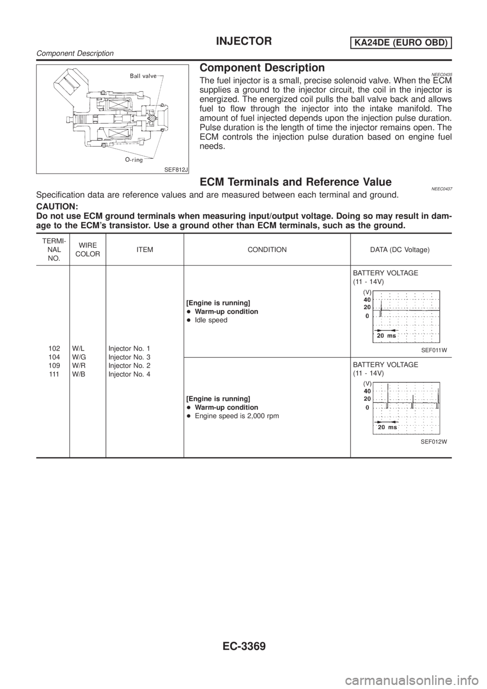
Component DescriptionNEEC0435The fuel injector is a small, precise solenoid valve. When the ECM
supplies a ground to the injector circuit, the coil in the injector is
energized. The energized coil pulls the ball valve back and allows
fuel to flow through the injector into the intake manifold. The
amount of fuel injected depends upon the injection pulse duration.
Pulse duration is the length of time the injector remains open. The
ECM controls the injection pulse duration based on engine fuel
needs.
ECM Terminals and Reference ValueNEEC0437Specification data are reference values and are measured between each terminal and ground.
CAUTION:
Do not use ECM ground terminals when measuring input/output voltage. Doing so may result in dam-
age to the ECM's transistor. Use a ground other than ECM terminals, such as the ground.
TERMI-
NAL
NO.WIRE
COLORITEM CONDITION DATA (DC Voltage)
102
104
109
111W/L
W/G
W/R
W/BInjector No. 1
Injector No. 3
Injector No. 2
Injector No. 4[Engine is running]
+Warm-up condition
+Idle speedBATTERY VOLTAGE
(11 - 14V)
SEF011W
[Engine is running]
+Warm-up condition
+Engine speed is 2,000 rpmBATTERY VOLTAGE
(11 - 14V)
SEF012W
INJECTORKA24DE (EURO OBD)
Component Description
EC-3369
Page 447 of 1306
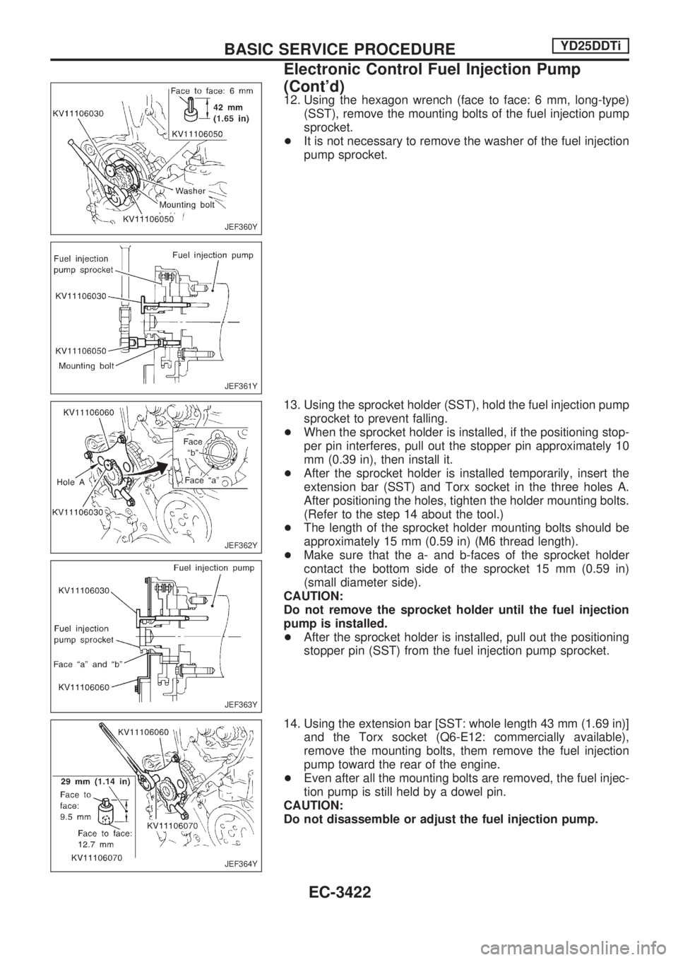
12. Using the hexagon wrench (face to face: 6 mm, long-type)
(SST), remove the mounting bolts of the fuel injection pump
sprocket.
+It is not necessary to remove the washer of the fuel injection
pump sprocket.
13. Using the sprocket holder (SST), hold the fuel injection pump
sprocket to prevent falling.
+When the sprocket holder is installed, if the positioning stop-
per pin interferes, pull out the stopper pin approximately 10
mm (0.39 in), then install it.
+After the sprocket holder is installed temporarily, insert the
extension bar (SST) and Torx socket in the three holes A.
After positioning the holes, tighten the holder mounting bolts.
(Refer to the step 14 about the tool.)
+The length of the sprocket holder mounting bolts should be
approximately 15 mm (0.59 in) (M6 thread length).
+Make sure that the a- and b-faces of the sprocket holder
contact the bottom side of the sprocket 15 mm (0.59 in)
(small diameter side).
CAUTION:
Do not remove the sprocket holder until the fuel injection
pump is installed.
+After the sprocket holder is installed, pull out the positioning
stopper pin (SST) from the fuel injection pump sprocket.
14. Using the extension bar [SST: whole length 43 mm (1.69 in)]
and the Torx socket (Q6-E12: commercially available),
remove the mounting bolts, them remove the fuel injection
pump toward the rear of the engine.
+Even after all the mounting bolts are removed, the fuel injec-
tion pump is still held by a dowel pin.
CAUTION:
Do not disassemble or adjust the fuel injection pump.
JEF360Y
JEF361Y
JEF362Y
JEF363Y
JEF364Y
BASIC SERVICE PROCEDUREYD25DDTi
Electronic Control Fuel Injection Pump
(Cont'd)
EC-3422
Page 692 of 1306
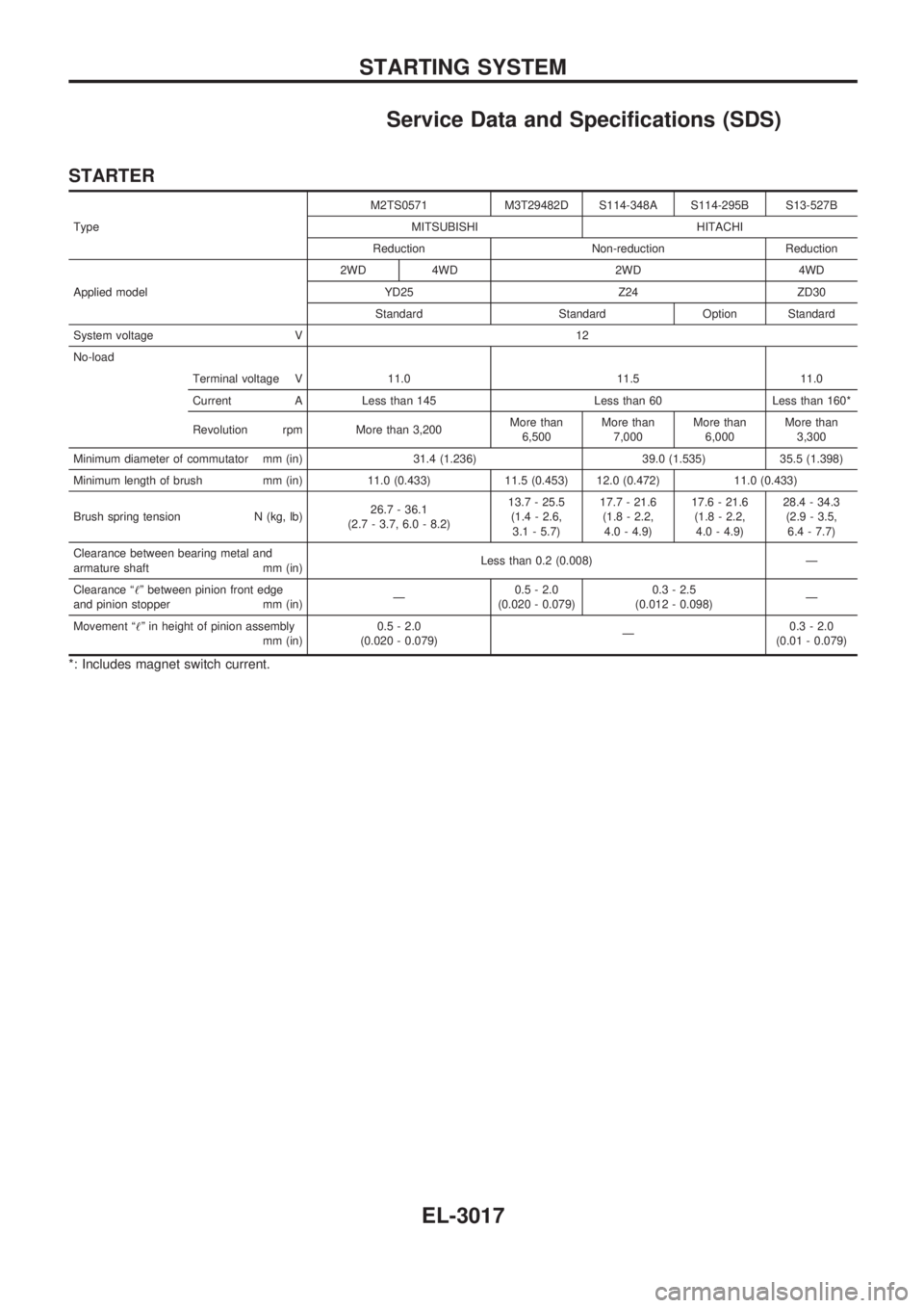
Service Data and Specifications (SDS)
STARTER
TypeM2TS0571 M3T29482D S114-348A S114-295B S13-527B
MITSUBISHI HITACHI
Reduction Non-reduction Reduction
Applied model2WD 4WD 2WD 4WD
YD25 Z24 ZD30
Standard Standard Option Standard
System voltage V 12
No-load
Terminal voltage V 11.0 11.5 11.0
Current A Less than 145 Less than 60 Less than 160*
Revolution rpm More than 3,200More than
6,500More than
7,000More than
6,000More than
3,300
Minimum diameter of commutator mm (in) 31.4 (1.236) 39.0 (1.535) 35.5 (1.398)
Minimum length of brush mm (in) 11.0 (0.433) 11.5 (0.453) 12.0 (0.472) 11.0 (0.433)
Brush spring tension N (kg, lb)26.7 - 36.1
(2.7 - 3.7, 6.0 - 8.2)13.7 - 25.5
(1.4 - 2.6,
3.1 - 5.7)17.7 - 21.6
(1.8 - 2.2,
4.0 - 4.9)17.6 - 21.6
(1.8 - 2.2,
4.0 - 4.9)28.4 - 34.3
(2.9 - 3.5,
6.4 - 7.7)
Clearance between bearing metal and
armature shaft mm (in)Less than 0.2 (0.008) Ð
Clearance ª!º between pinion front edge
and pinion stopper mm (in)Ð0.5 - 2.0
(0.020 - 0.079)0.3 - 2.5
(0.012 - 0.098)Ð
Movement ª!º in height of pinion assembly
mm (in)0.5 - 2.0
(0.020 - 0.079)Ð0.3 - 2.0
(0.01 - 0.079)
*: Includes magnet switch current.
STARTING SYSTEM
EL-3017
Page 697 of 1306
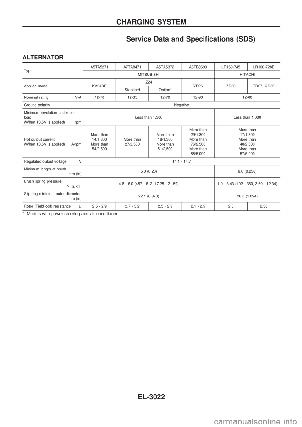
Service Data and Specifications (SDS)
ALTERNATOR
TypeA5TA5271 A7TA8471 A5TA5372 A3TB0699 LR160-745 LR160-728E
MITSUBISHI HITACHI
Applied model KA24DEZ24
YD25 ZD30 TD27, QD32
Standard Option*
Nominal rating V-A 12-70 12-35 12-70 12-90 12-60
Ground polarityNegative
Minimum revolution under no-
load
(When 13.5V is applied) rpmLess than 1,300 Less than 1,000
Hot output current
(When 13.5V is applied) A/rpmMore than
14/1,300
More than
54/2,500More than
27/2,500More than
18/1,300
More than
51/2,500More than
29/1,300
More than
76/2,500
More than
88/5,000More than
17/1,300
More than
48/2,500
More than
57/5,000
Regulated output voltage V 14.1 - 14.7
Minimum length of brush
mm (in)5.0 (0.20) 6.0 (0.236)
Brush spring pressure
N (g, oz)4.8 - 6.0 (487 - 612, 17.25 - 21.59) 1.0 - 3.43 (102 - 350, 3.60 - 12.34)
Slip ring minimum outer diameter
mm (in)22.1 (0.870) 26.0 (1.024)
Rotor (Field coil) resistanceW2.5 - 2.9 2.7 - 3.2 2.5 - 2.9 2.1 - 2.5 2.6 2.58
*: Models with power steering and air conditioner
CHARGING SYSTEM
EL-3022
Page 896 of 1306
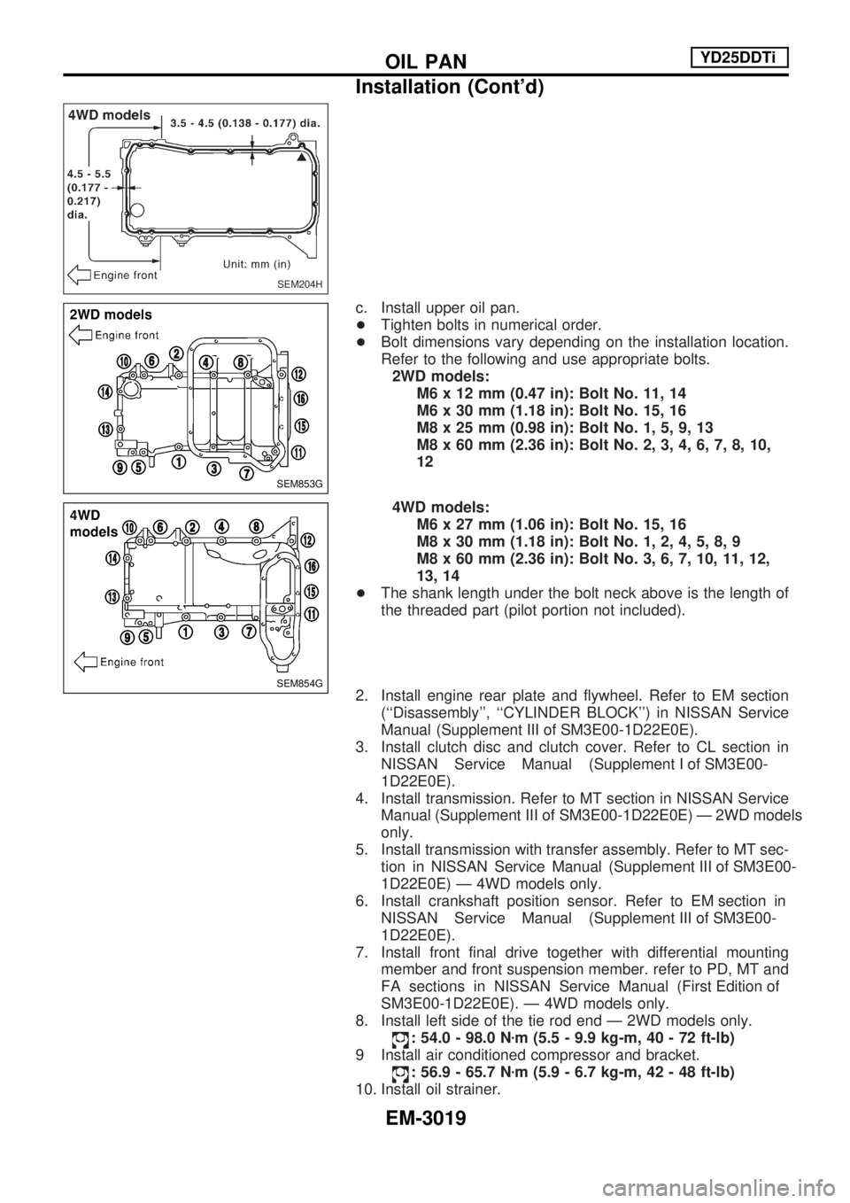
c. Install upper oil pan.
+Tighten bolts in numerical order.
+ Bolt dimensions vary depending on the installation location.
Refer to the following and use appropriate bolts.
2WD models: M6 x 12 mm (0.47 in): Bolt No. 11, 14
M6 x 30 mm (1.18 in): Bolt No. 15, 16
M8 x 25 mm (0.98 in): Bolt No. 1, 5, 9, 13
M8 x 60 mm (2.36 in): Bolt No. 2, 3, 4, 6, 7, 8, 10,
12
4WD models: M6 x 27 mm (1.06 in): Bolt No. 15, 16
M8 x 30 mm (1.18 in): Bolt No. 1, 2, 4, 5, 8, 9
M8 x 60 mm (2.36 in): Bolt No. 3, 6, 7, 10, 11, 12,
13, 14
+ The shank length under the bolt neck above is the length of
the threaded part (pilot portion not included).
2. Install engine rear plate and flywheel. Refer to EM section (``Disassembly'', ``CYLINDER BLOCK'') in NISSAN Service
Manual(Supplement III of SM3E00-1D22E0E).
3. Install clutch disc and clutch cover. Refer to CL section in NISSANServiceManual(Supplement I of SM3E00-
1D22E0E).
4. Install transmission. Refer to MT section in NISSAN Service Manual(Supplement III of SM3E00-1D22E0E)Ð2WDmodels
only.
5. Install transmission with transfer assembly. Refer to MT sec- tioninNISSANServiceManual(Supplement III of SM3E00-
1D22E0E) Ð 4WD models only.
6.Installcrankshaftpositionsensor.RefertoEM sectionin NISSANServiceManual(Supplement III of SM3E00-
1D22E0E).
7. Install front final drive together with differential mounting member and front suspension member. refer to PD, MT and
FAsectionsinNISSANServiceManual(First Edition of
SM3E00-1D22E0E). Ð 4WD models only.
8. Install left side of the tie rod end Ð 2WD models only.
: 54.0 - 98.0 N zm (5.5 - 9.9 kg-m, 40 - 72 ft-lb)
9 Install air conditioned compressor and bracket.
: 56.9 - 65.7 N zm (5.9 - 6.7 kg-m, 42 - 48 ft-lb)
10. Install oil strainer.
SEM204H
SEM853G
SEM854G
OILPAN YD25DDTi
Installation (Cont'd)
EM-3019
Page 904 of 1306
CAUTION:
+After removing timing chain, do not turn crankshaft and
camshaft separately, or valves will strike piston heads.
+When installing camshafts, chain tensioners, oil seals,
or other sliding parts, lubricate contacting surfaces with
new engine oil.
+Apply new engine oil to bolt threads and seat surfaces
when installing camshaft sprockets, crankshaft pulley,
and camshaft brackets.
+Do not spill engine coolant on drive belts.
REMOVAL
1. Remove charge air cooler and bracket.
2. Remove rocker cover. Refer to EM-3045, ªRemoval and
Installationº, ªROCKER COVERº.
3. Remove EGR guide tube.
4. Remove radiator shroud and radiator. Refer to LC section,
ªREMOVAL AND INSTALLATIONº, ªRadiatorº.
5. Remove idler pulley, idler pulley bracket and drive belts.
6. Remove upper and lower oil pans. Refer to EM-3015,
ªRemoval
and Installationº, ªOIL PANº.
7. Remove injection tube.
Refer to EC section, ªInjection Tube and Injection Nozzleº.
8. Remove secondary timing chain and associated parts.
Refer to EM-3021, ªSecondary Timing Chainº.
9. When removing rear chain case, remove camshaft sprock-
ets.
Refer to EM-3047, ªCAMSHAFTº.
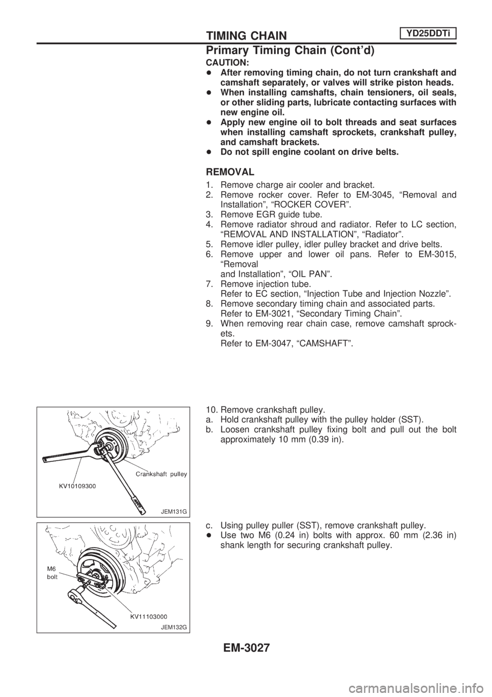
10. Remove crankshaft pulley.
a. Hold crankshaft pulley with the pulley holder (SST).
b. Loosen crankshaft pulley fixing bolt and pull out the bolt
approximately 10 mm (0.39 in).
c. Using pulley puller (SST), remove crankshaft pulley.
+Use two M6 (0.24 in) bolts with approx. 60 mm (2.36 in)
shank length for securing crankshaft pulley.
JEM131G
JEM132G
TIMING CHAINYD25DDTi
Primary Timing Chain (Cont'd)
EM-3027