2001 NISSAN PICK-UP timing belt
[x] Cancel search: timing beltPage 26 of 1306

ENGINE CONTROL SYSTEM
SECTION
EC
CONTENTS
PRECAUTIONS AND PREPARATION............... 3008
Special Service Tool (YD25DDTi) ................... 3008
Supplemental Restraint System (SRS)²AIR
BAG²................................................................ 3008
KA24DE (EURO OBD)
Trouble Diagnosis - Index................................. 3009
Alphabetical & P No. Index for DTC................ 3009
Precautions......................................................... 3012
Supplemental Restraint System (SRS)²AIR
BAG²and²SEAT BELT PRE-TENSIONER².. 3012
Precautions for On Board Diagnostic (OBD)
System of Engine............................................. 3012
Engine Fuel & Emission Control System ........ 3013
Precautions ...................................................... 3014
Wiring Diagrams and Trouble Diagnosis ......... 3015
Preparation.......................................................... 3016
Special Service Tools ...................................... 3016
Commercial Service Tools ............................... 3016
Engine and Emission Control Overall System3018
Engine Control Component Parts Location ..... 3018
Circuit Diagram ................................................ 3020
System Diagram .............................................. 3021
Vacuum Hose Drawing .................................... 3022
System Chart ................................................... 3023
Engine and Emission Basic Control System
Description.......................................................... 3024
Multiport Fuel Injection (MFI) System.............. 3024
Distributor Ignition (DI) System........................ 3026
Air Conditioning Cut Control ............................ 3028
Fuel Cut Control (at no load & high engine
speed) .............................................................. 3028Evaporative Emission System ......................... 3029
Positive Crankcase Ventilation ........................ 3032
Basic Service Procedure................................... 3033
Fuel Pressure Release .................................... 3033
Fuel Pressure Check ....................................... 3033
Fuel Pressure Regulator Check ...................... 3034
Injector ............................................................. 3034
Fast Idle Cam (FIC) ......................................... 3035
Idle Speed/Ignition Timing/Idle Mixture Ratio
Adjustment ....................................................... 3035
On Board Diagnostic System Description...... 3049
Introduction ...................................................... 3049
Two Trip Detection Logic ................................. 3049
Emission-related Diagnostic Information ......... 3049
NVIS (Nissan Vehicle Immobilizer System -
NATS) .............................................................. 3061
Malfunction Indicator (MI) ................................ 3061
OBD System Operation Chart ......................... 3064
CONSULT-II ..................................................... 3070
Generic Scan Tool (GST) ................................ 3080
Trouble Diagnosis - Introduction..................... 3082
Introduction ...................................................... 3082
Work Flow ........................................................ 3084
Trouble Diagnosis - Basic Inspection.............. 3086
Basic Inspection ............................................... 3086
Trouble Diagnosis - General Description........ 3100
DTC Inspection Priority Chart .......................... 3100
Fail-safe Chart ................................................. 3101
Symptom Matrix Chart ..................................... 3102
CONSULT-II Reference Value in Data Monitor
Mode ................................................................ 3106
Major Sensor Reference Graph in Data
Monitor Mode ................................................... 3107
BR
Page 889 of 1306

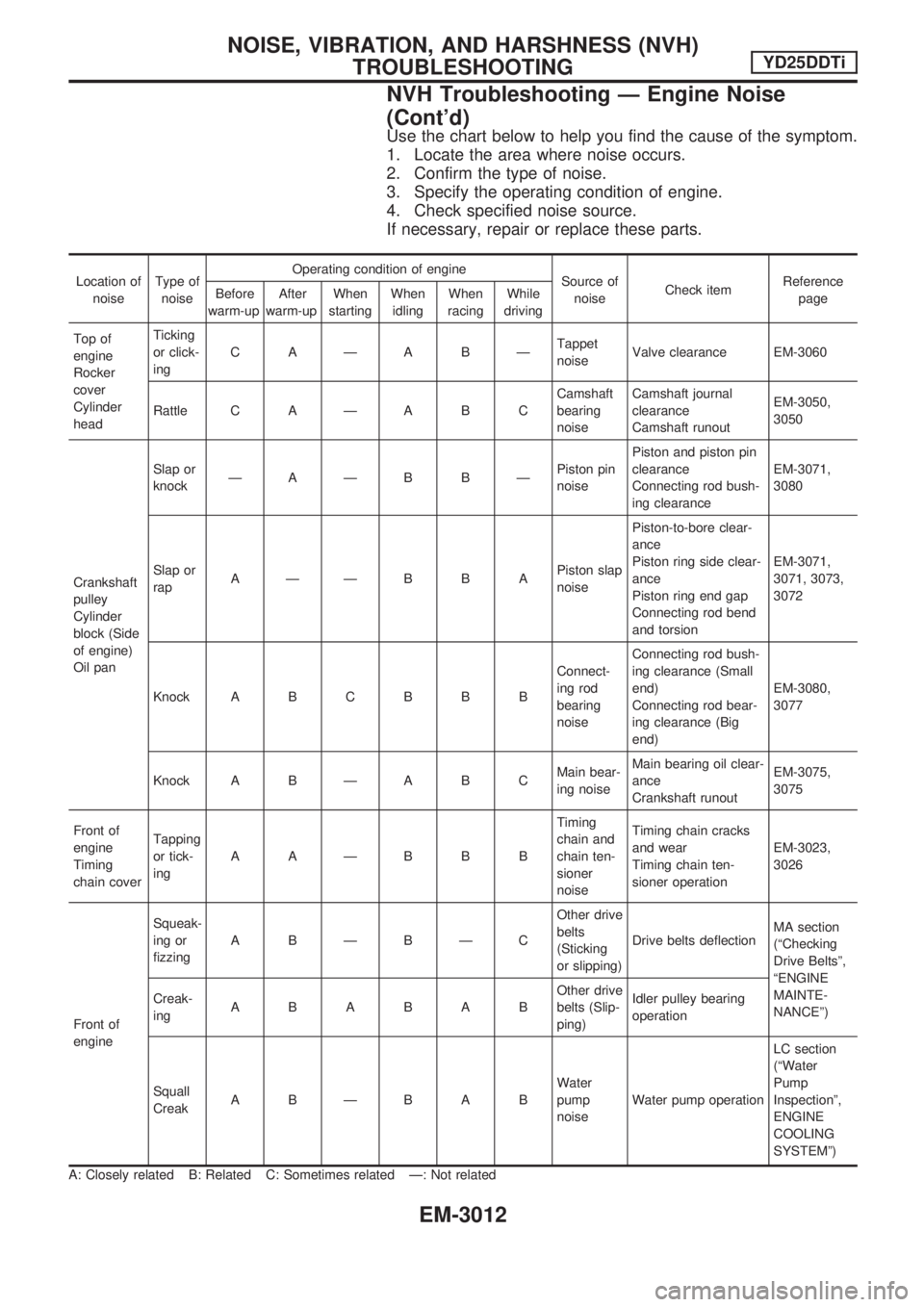
Use the chart below to help you find the cause of the symptom.
1. Locate the area where noise occurs.
2. Confirm the type of noise.
3. Specify the operating condition of engine.
4. Check specified noise source.
If necessary, repair or replace these parts.
Location of
noiseType of
noiseOperating condition of engine
Source of
noiseCheck itemReference
page Before
warm-upAfter
warm-upWhen
startingWhen
idlingWhen
racingWhile
driving
Top of
engine
Rocker
cover
Cylinder
headTicking
or click-
ingCAÐABÐTappet
noiseValve clearance EM-3060
Rattle C A Ð A B CCamshaft
bearing
noiseCamshaft journal
clearance
Camshaft runoutEM-3050,
3050
Crankshaft
pulley
Cylinder
block (Side
of engine)
Oil panSlap or
knockÐAÐB BÐPiston pin
noisePiston and piston pin
clearance
Connecting rod bush-
ing clearanceEM-3071,
3080
Slap or
rapAÐÐBBAPiston slap
noisePiston-to-bore clear-
ance
Piston ring side clear-
ance
Piston ring end gap
Connecting rod bend
and torsionEM-3071,
3071, 3073,
3072
Knock A B C B B BConnect-
ing rod
bearing
noiseConnecting rod bush-
ing clearance (Small
end)
Connecting rod bear-
ing clearance (Big
end)EM-3080,
3077
Knock A B Ð A B CMain bear-
ing noiseMain bearing oil clear-
ance
Crankshaft runoutEM-3075,
3075
Front of
engine
Timing
chain coverTapping
or tick-
ingAAÐBBBTiming
chain and
chain ten-
sioner
noiseTiming chain cracks
and wear
Timing chain ten-
sioner operationEM-3023,
3026
Front of
engineSqueak-
ing or
fizzingABÐBÐCOther drive
belts
(Sticking
or slipping)Drive belts deflectionMA section
(ªChecking
Drive Beltsº,
ªENGINE
MAINTE-
NANCEº) Creak-
ingABABABOther drive
belts (Slip-
ping)Idler pulley bearing
operation
Squall
CreakABÐBABWater
pump
noiseWater pump operationLC section
(ªWater
Pump
Inspectionº,
ENGINE
COOLING
SYSTEMº)
A: Closely related B: Related C: Sometimes related Ð: Not related
NOISE, VIBRATION, AND HARSHNESS (NVH)
TROUBLESHOOTINGYD25DDTi
NVH Troubleshooting Ð Engine Noise
(Cont'd)
EM-3012
Page 898 of 1306

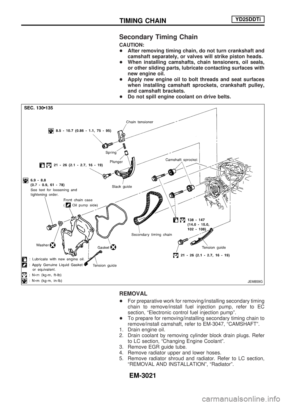
Secondary Timing Chain
CAUTION:
+After removing timing chain, do not turn crankshaft and
camshaft separately, or valves will strike piston heads.
+When installing camshafts, chain tensioners, oil seals,
or other sliding parts, lubricate contacting surfaces with
new engine oil.
+Apply new engine oil to bolt threads and seat surfaces
when installing camshaft sprockets, crankshaft pulley,
and camshaft brackets.
+Do not spill engine coolant on drive belts.
REMOVAL
+For preparative work for removing/installing secondary timing
chain to remove/install fuel injection pump, refer to EC
section, ªElectronic control fuel injection pumpº.
+To prepare for removing/installing secondary timing chain to
remove/install camshaft, refer to EM-3047, ªCAMSHAFTº.
1. Drain engine oil.
2. Drain coolant by removing cylinder block drain plugs. Refer
to LC section, ªChanging Engine Coolantº.
3. Remove EGR guide tube.
4. Remove radiator upper and lower hoses.
5. Remove radiator shroud and radiator. Refer to LC section,
ªREMOVAL AND INSTALLATIONº, ªRadiatorº.
JEM859G
TIMING CHAINYD25DDTi
EM-3021
Page 904 of 1306

CAUTION:
+After removing timing chain, do not turn crankshaft and
camshaft separately, or valves will strike piston heads.
+When installing camshafts, chain tensioners, oil seals,
or other sliding parts, lubricate contacting surfaces with
new engine oil.
+Apply new engine oil to bolt threads and seat surfaces
when installing camshaft sprockets, crankshaft pulley,
and camshaft brackets.
+Do not spill engine coolant on drive belts.
REMOVAL
1. Remove charge air cooler and bracket.
2. Remove rocker cover. Refer to EM-3045, ªRemoval and
Installationº, ªROCKER COVERº.
3. Remove EGR guide tube.
4. Remove radiator shroud and radiator. Refer to LC section,
ªREMOVAL AND INSTALLATIONº, ªRadiatorº.
5. Remove idler pulley, idler pulley bracket and drive belts.
6. Remove upper and lower oil pans. Refer to EM-3015,
ªRemoval
and Installationº, ªOIL PANº.
7. Remove injection tube.
Refer to EC section, ªInjection Tube and Injection Nozzleº.
8. Remove secondary timing chain and associated parts.
Refer to EM-3021, ªSecondary Timing Chainº.
9. When removing rear chain case, remove camshaft sprock-
ets.
Refer to EM-3047, ªCAMSHAFTº.
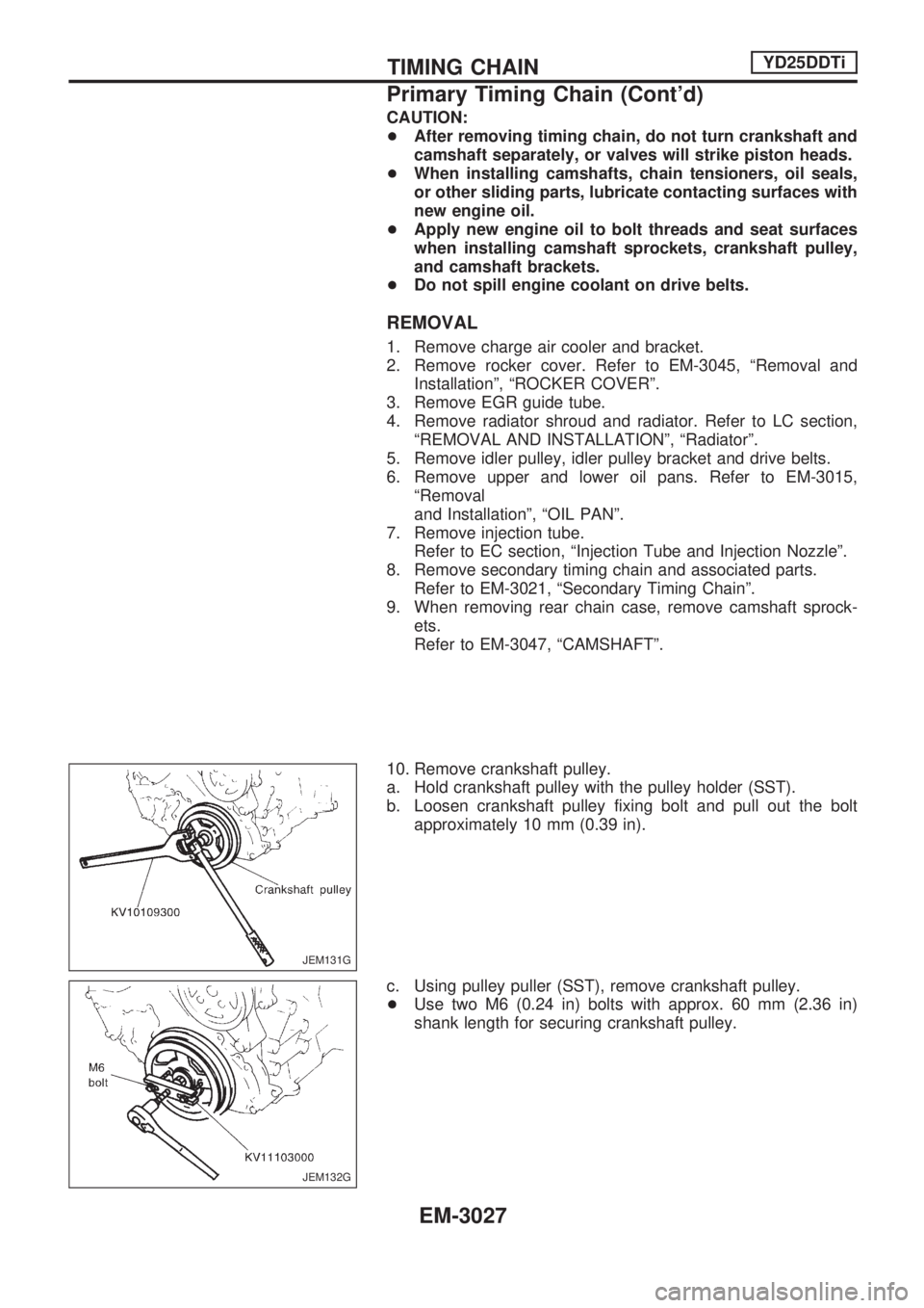
10. Remove crankshaft pulley.
a. Hold crankshaft pulley with the pulley holder (SST).
b. Loosen crankshaft pulley fixing bolt and pull out the bolt
approximately 10 mm (0.39 in).
c. Using pulley puller (SST), remove crankshaft pulley.
+Use two M6 (0.24 in) bolts with approx. 60 mm (2.36 in)
shank length for securing crankshaft pulley.
JEM131G
JEM132G
TIMING CHAINYD25DDTi
Primary Timing Chain (Cont'd)
EM-3027
Page 1065 of 1306

S
S/SIG - Wiring diagram ......................... EC-3375
SMJ (super multiple junction) ................ EL-3198
SRS - See Supplemental Restraint
System .............................................. RS-3003
START - Wiring diagram ....................... EL-3014
STOP/L - Wiring diagram ...................... EL-3043
Seat belt pre-tensioner disposal ........... RS-3011
Seat belt pre-tensioner ......................... RS-3003
Self-diagnostic results ................. EC-3429, 3430
Shift control (Transfer) ........................... TF-3005
Side air bag ........................................... RS-3003
Spiral cable ........................................... RS-3006
Spot lamp .............................................. EL-3055
Start signal ............................................ EC-3374
Starter .................................................... EL-3017
Starting system ...................................... EL-3014
Stop lamp .............................................. EL-3043
Supplemental Restraint System ........... RS-3003
Supplemental restraint system - Wiring
diagram ............................................. RS-3018
Symptom matrix chart ...... EC-3102, 3450, 3451
System readiness test (SRT) code ....... EC-3051
T
TAIL/L - Wiring diagram ........................ EL-3039
THEFT - Wiring diagram ....................... EL-3142
TP/SW - Wiring diagram ....................... EC-3303
TPS - Wiring diagram ................. EC-3174, 3185
TURN - Wiring diagram ......................... EL-3047
Tail lamp ................................................ EL-3039
Theft warning system ............................ EL-3142
Thermostat ............................................ LC-3014
Three way catalyst ................................ EC-3278Throttle bodies ...................................... EM-3008
Throttle chambers ................................. EM-3008
Throttle position sensor (TPS) .... EC-3170, 3182
Throttle position sensor adjustment ...... EC-3086
Throttle position switch ......................... EC-3301
Timing chain ......................................... EM-3021
Tire size .................................................. GI-3007
Turn signal lamp .................................... EL-3047
Two trip detection logic ......................... EC-3049
V
VSS - Wiring diagram ........................... EC-3292
Vacuum hose drawing (Engine
control) .............................................. EC-3022
Valve clearance .................................... EM-3060
Valve guide ........................................... EM-3052
Valve seat ............................................. EM-3053
Valve spring .......................................... EM-3055
Vehicle identification number ................. GI-3005
Vehicle speed sensor
(VSS) ............................ EC-3290, 3484, 3485
W
WARN - Wiring diagram ........................ EL-3083
WINDOW - Wiring diagram ................... EL-3123
Warning lamps ....................................... EL-3081
Water pump ........................................... LC-3012
Wheel size .............................................. GI-3007
Wide open & closed throttle position
switch ...................................... EC-3170, 3182
Wiring diagram (cell code) list ............... EL-3196
Wrist pin - See Piston pin inspection ... EM-3071
ALPHABETICAL INDEX
IDX-3005