2001 NISSAN PICK-UP brake sensor
[x] Cancel search: brake sensorPage 11 of 1306

BRAKE SYSTEM
SECTION
BR
MODIFICATION NOTICE:
lWiring Diagrams have been changed.
CONTENTS
TROUBLE DIAGNOSES..................................... 3002
Schematic/3 Wheel Sensors Models ............... 3002
Wiring Diagram - ABS -/3 Wheel Sensors LHD
Models.............................................................. 3003
Wiring Diagram - ABS -/3 Wheel Sensors
RHD Models..................................................... 3006Schematic/4 Wheel Sensors Models ............... 3009
Wiring Diagram - ABS -/4 Wheel Sensors LHD
Models.............................................................. 3010
Wiring Diagram - ABS -/4 Wheel Sensors
RHD Models..................................................... 3013
BR
Page 460 of 1306
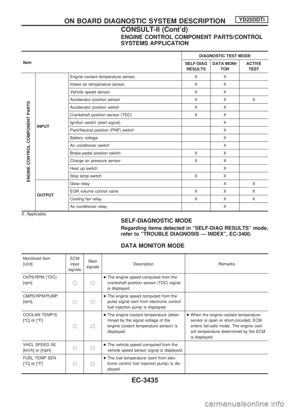
ENGINE CONTROL COMPONENT PARTS/CONTROL
SYSTEMS APPLICATION
ItemDIAGNOSTIC TEST MODE
SELF-DIAG
RESULTSDATA MONI-
TORACTIVE
TEST
ENGINE CONTROL COMPONENT PARTS
INPUTEngine coolant temperature sensor X X
Intake air temperature sensor X X
Vehicle speed sensor X X
Accelerator position sensor X X X
Accelerator position switch X X
Crankshaft position sensor (TDC) X X
Ignition switch (start signal) X
Park/Neutral position (PNP) switch X
Battery voltage X
Air conditioner switch X
Brake pedal position switch X X
Charge air pressure sensor X X
Heat up switch X
Stop lamp switch X X
OUTPUTGlow relayXX
EGR volume control valve X X X
Cooling fan relay X X X
Air conditioner relay X
X: Applicable
SELF-DIAGNOSTIC MODE
Regarding items detected in ªSELF-DIAG RESULTSº mode,
refer to ªTROUBLE DIAGNOSIS Ð INDEXº, EC-3400.
DATA MONITOR MODE
Monitored item
[Unit]ECM
input
signalsMain
signalsDescription Remarks
CKPSzRPM (TDC)
[rpm]jj+The engine speed computed from the
crankshaft position sensor (TDC) signal
is displayed.
CMPSzRPMzPUMP
[rpm]jj+The engine speed computed from the
pulse signal sent from electronic control
fuel injection pump is displayed.
COOLAN TEMP/S
[ÉC] or [ÉF]
jj+The engine coolant temperature (deter-
mined by the signal voltage of the
engine coolant temperature sensor) is
displayed.+When the engine coolant temperature
sensor is open or short-circuited, ECM
enters fail-safe mode. The engine cool-
ant temperature determined by the ECM
is displayed.
VHCL SPEED SE
[km/h] or [mph]jj+The vehicle speed computed from the
vehicle speed sensor signal is displayed.
FUEL TEMP SEN
[ÉC] or [ÉF]jj+The fuel temperature (sent from elec-
tronic control fuel injection pump) is dis-
played.
ON BOARD DIAGNOSTIC SYSTEM DESCRIPTIONYD25DDTi
CONSULT-II (Cont'd)
EC-3435
Page 461 of 1306
![NISSAN PICK-UP 2001 Repair Manual Monitored item
[Unit]ECM
input
signalsMain
signalsDescription Remarks
ACCEL POS SEN [V]
jj+The accelerator position sensor signal
voltage is displayed.
FULL ACCEL SW
[ON/OFF]jj+Indicates [ON/OFF] cond NISSAN PICK-UP 2001 Repair Manual Monitored item
[Unit]ECM
input
signalsMain
signalsDescription Remarks
ACCEL POS SEN [V]
jj+The accelerator position sensor signal
voltage is displayed.
FULL ACCEL SW
[ON/OFF]jj+Indicates [ON/OFF] cond](/manual-img/5/57372/w960_57372-460.png)
Monitored item
[Unit]ECM
input
signalsMain
signalsDescription Remarks
ACCEL POS SEN [V]
jj+The accelerator position sensor signal
voltage is displayed.
FULL ACCEL SW
[ON/OFF]jj+Indicates [ON/OFF] condition from the
accelerator position switch signal.
OFF ACCEL SW
[ON/OFF]jj+Indicates [ON/OFF] condition from the
accelerator position switch signal.
SPILL/V [ÉCA]
j+The control position of spill valve (sent
from electronic control fuel injection
pump) is displayed.
BATTERY VOLT [V]
jj+The power supply voltage of ECM is dis-
played.
I/C INT/A T/S [V]
jj+The signal voltage of the intake air tem-
perature sensor is displayed.
P/N POSI SW
[ON/OFF]jj+Indicates [ON/OFF] condition from the
park/neutral position switch signal.
START SIGNAL
[ON/OFF]jj+Indicates [ON/OFF] condition from the
starter signal.+After starting the engine, [OFF] is dis-
played regardless of the starter signal.
AIR COND SIG
[ON/OFF]jj+Indicates [ON/OFF] condition of the air
conditioner switch as determined by the
air conditioner signal.
BRAKE SW [ON/OFF]
jj+Indicates [ON/OFF] condition from the
stop lamp switch signal.
BRAKE SW2
[ON/OFF]jj+Indicates [ON/OFF] condition from the
brake pedal position switch.
IGN SW
[ON/OFF]jj+Indicates [ON/OFF] condition from igni-
tion switch signal.
WARM UP SW
[ON/OFF]j+Indicates [ON/OFF] condition from the
heat up switch signal.
TURBO BST SEN
[kPa]j+The charge air pressure (determined by
the signal voltage sent to the ECM) is
displayed.
DECELER F/CUT
[ON/OFF]j+The [ON/OFF] condition from decelera-
tion fuel cut signal (sent from ECM) is
displayed.
INJ TIMG C/V [%]
j+The duty ratio of fuel injection timing
control valve (sent from electronic con-
trol fuel injection pump) is displayed.
AIR COND RLY
[ON/OFF]j+Indicates the control condition of the air
conditioner relay (determined by ECM
according to the input signals).
GLOW RLY [ON/OFF]
j+The glow relay control condition (deter-
mined by ECM according to the input
signal) is displayed.
COOLING FAN
[ON/OFF]
j+Indicates the control condition of the
cooling fans (determined by ECM
according to the input signal).
+ON ... Operates.
OFF ... Stopped.
ON BOARD DIAGNOSTIC SYSTEM DESCRIPTIONYD25DDTi
CONSULT-II (Cont'd)
EC-3436
Page 490 of 1306
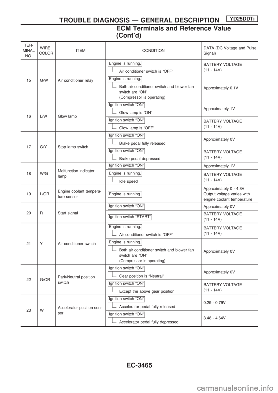
TER-
MINAL
NO.WIRE
COLORITEM CONDITIONDATA (DC Voltage and Pulse
Signal)
15 G/W Air conditioner relayEngine is running.
Air conditioner switch is ªOFFºBATTERY VOLTAGE
(11 - 14V)
Engine is running.
Both air conditioner switch and blower fan
switch are ªONº
(Compressor is operating)Approximately 0.1V
16 L/W Glow lampIgnition switch ªONº
Glow lamp is ªONºApproximately 1V
Ignition switch ªONº
Glow lamp is ªOFFºBATTERY VOLTAGE
(11 - 14V)
17 G/Y Stop lamp switchIgnition switch ªONº
Brake pedal fully releasedApproximately 0V
Ignition switch ªONº
Brake pedal depressedBATTERY VOLTAGE
(11 - 14V)
18 W/GMalfunction indicator
lampIgnition switch ªONº
Approximately 1V
Engine is running.
Idle speedBATTERY VOLTAGE
(11 - 14V)
19 L/OREngine coolant tempera-
ture sensorEngine is running.
Approximately 0 - 4.8V
Output voltage varies with
engine coolant temperature
20 R Start signalIgnition switch ªONº
Approximately 0V
Ignition switch ªSTARTº
BATTERY VOLTAGE
(11 - 14V)
21 Y Air conditioner switchEngine is running.
Air conditioner switch is ªOFFºBATTERY VOLTAGE
(11 - 14V)
Engine is running.
Both air conditioner switch and blower fan
switch are ªONº
(Compressor is operating)Approximately 0V
22 G/ORPark/Neutral position
switchIgnition switch ªONº
Gear position is ªNeutralºApproximately 0V
Ignition switch ªONº
Except the above gear positionBATTERY VOLTAGE
(11 - 14V)
23 WAccelerator position sen-
sorIgnition switch ªONº
Accelerator pedal fully released0.29 - 0.79V
Ignition switch ªONº
Accelerator pedal fully depressed3.48 - 4.64V
TROUBLE DIAGNOSIS Ð GENERAL DESCRIPTIONYD25DDTi
ECM Terminals and Reference Value
(Cont'd)
EC-3465
Page 491 of 1306
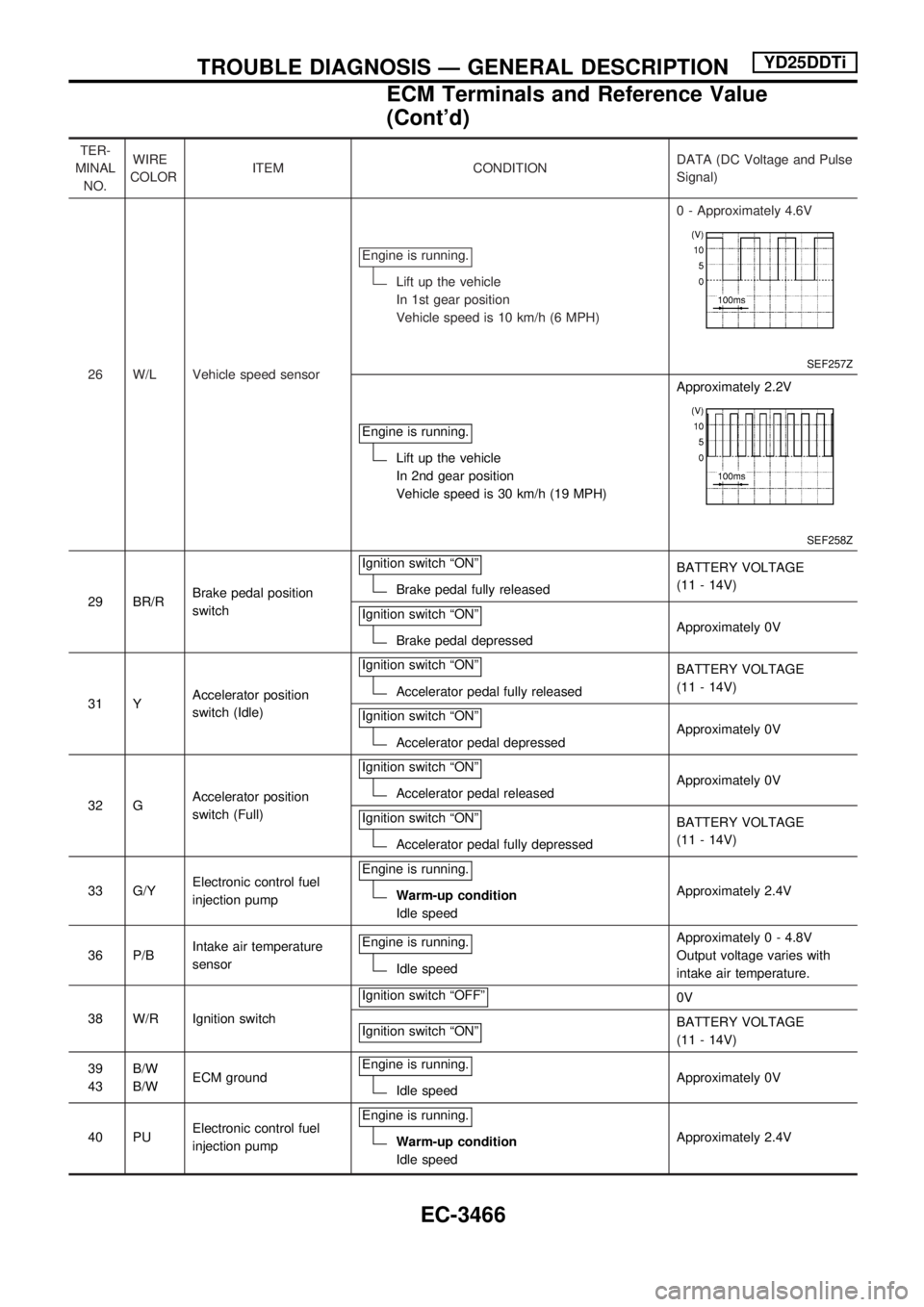
TER-
MINAL
NO.WIRE
COLORITEM CONDITIONDATA (DC Voltage and Pulse
Signal)
26 W/L Vehicle speed sensorEngine is running.
Lift up the vehicle
In 1st gear position
Vehicle speed is 10 km/h (6 MPH)0 - Approximately 4.6V
SEF257Z
Engine is running.
Lift up the vehicle
In 2nd gear position
Vehicle speed is 30 km/h (19 MPH)Approximately 2.2V
SEF258Z
29 BR/RBrake pedal position
switchIgnition switch ªONºBrake pedal fully releasedBATTERY VOLTAGE
(11 - 14V)
Ignition switch ªONº
Brake pedal depressedApproximately 0V
31 YAccelerator position
switch (Idle)Ignition switch ªONº
Accelerator pedal fully releasedBATTERY VOLTAGE
(11 - 14V)
Ignition switch ªONº
Accelerator pedal depressedApproximately 0V
32 GAccelerator position
switch (Full)Ignition switch ªONº
Accelerator pedal releasedApproximately 0V
Ignition switch ªONº
Accelerator pedal fully depressedBATTERY VOLTAGE
(11 - 14V)
33 G/YElectronic control fuel
injection pumpEngine is running.
Warm-up condition
Idle speedApproximately 2.4V
36 P/BIntake air temperature
sensorEngine is running.
Idle speedApproximately 0 - 4.8V
Output voltage varies with
intake air temperature.
38 W/R Ignition switchIgnition switch ªOFFº
0V
Ignition switch ªONº
BATTERY VOLTAGE
(11 - 14V)
39
43B/W
B/WECM groundEngine is running.
Idle speedApproximately 0V
40 PUElectronic control fuel
injection pumpEngine is running.
Warm-up condition
Idle speedApproximately 2.4V
TROUBLE DIAGNOSIS Ð GENERAL DESCRIPTIONYD25DDTi
ECM Terminals and Reference Value
(Cont'd)
EC-3466
Page 869 of 1306
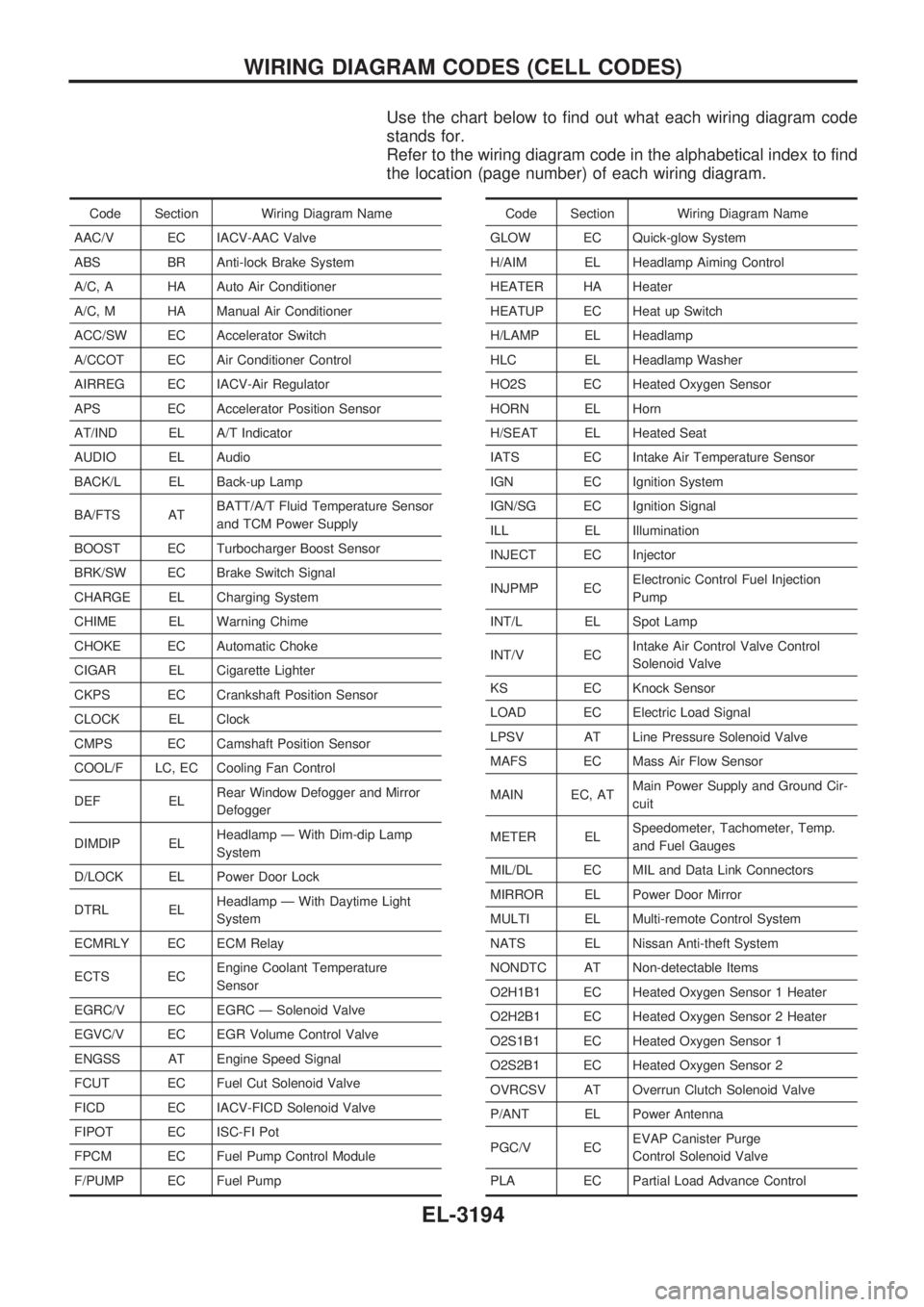
Use the chart below to find out what each wiring diagram code
stands for.
Refer to the wiring diagram code in the alphabetical index to find
the location (page number) of each wiring diagram.
Code Section Wiring Diagram Name
AAC/V EC IACV-AAC Valve
ABS BR Anti-lock Brake System
A/C, A HA Auto Air Conditioner
A/C, M HA Manual Air Conditioner
ACC/SW EC Accelerator Switch
A/CCOT EC Air Conditioner Control
AIRREG EC IACV-Air Regulator
APS EC Accelerator Position Sensor
AT/IND EL A/T Indicator
AUDIO EL Audio
BACK/L EL Back-up Lamp
BA/FTS ATBATT/A/T Fluid Temperature Sensor
and TCM Power Supply
BOOST EC Turbocharger Boost Sensor
BRK/SW EC Brake Switch Signal
CHARGE EL Charging System
CHIME EL Warning Chime
CHOKE EC Automatic Choke
CIGAR EL Cigarette Lighter
CKPS EC Crankshaft Position Sensor
CLOCK EL Clock
CMPS EC Camshaft Position Sensor
COOL/F LC, EC Cooling Fan Control
DEF ELRear Window Defogger and Mirror
Defogger
DIMDIP ELHeadlamp Ð With Dim-dip Lamp
System
D/LOCK EL Power Door Lock
DTRL ELHeadlamp Ð With Daytime Light
System
ECMRLY EC ECM Relay
ECTS ECEngine Coolant Temperature
Sensor
EGRC/V EC EGRC Ð Solenoid Valve
EGVC/V EC EGR Volume Control Valve
ENGSS AT Engine Speed Signal
FCUT EC Fuel Cut Solenoid Valve
FICD EC IACV-FICD Solenoid Valve
FIPOT EC ISC-FI Pot
FPCM EC Fuel Pump Control Module
F/PUMP EC Fuel PumpCode Section Wiring Diagram Name
GLOW EC Quick-glow System
H/AIM EL Headlamp Aiming Control
HEATER HA Heater
HEATUP EC Heat up Switch
H/LAMP EL Headlamp
HLC EL Headlamp Washer
HO2S EC Heated Oxygen Sensor
HORN EL Horn
H/SEAT EL Heated Seat
IATS EC Intake Air Temperature Sensor
IGN EC Ignition System
IGN/SG EC Ignition Signal
ILL EL Illumination
INJECT EC Injector
INJPMP ECElectronic Control Fuel Injection
Pump
INT/L EL Spot Lamp
INT/V ECIntake Air Control Valve Control
Solenoid Valve
KS EC Knock Sensor
LOAD EC Electric Load Signal
LPSV AT Line Pressure Solenoid Valve
MAFS EC Mass Air Flow Sensor
MAIN EC, ATMain Power Supply and Ground Cir-
cuit
METER ELSpeedometer, Tachometer, Temp.
and Fuel Gauges
MIL/DL EC MIL and Data Link Connectors
MIRROR EL Power Door Mirror
MULTI EL Multi-remote Control System
NATS EL Nissan Anti-theft System
NONDTC AT Non-detectable Items
O2H1B1 EC Heated Oxygen Sensor 1 Heater
O2H2B1 EC Heated Oxygen Sensor 2 Heater
O2S1B1 EC Heated Oxygen Sensor 1
O2S2B1 EC Heated Oxygen Sensor 2
OVRCSV AT Overrun Clutch Solenoid Valve
P/ANT EL Power Antenna
PGC/V ECEVAP Canister Purge
Control Solenoid Valve
PLA EC Partial Load Advance Control
WIRING DIAGRAM CODES (CELL CODES)
EL-3194
Page 940 of 1306
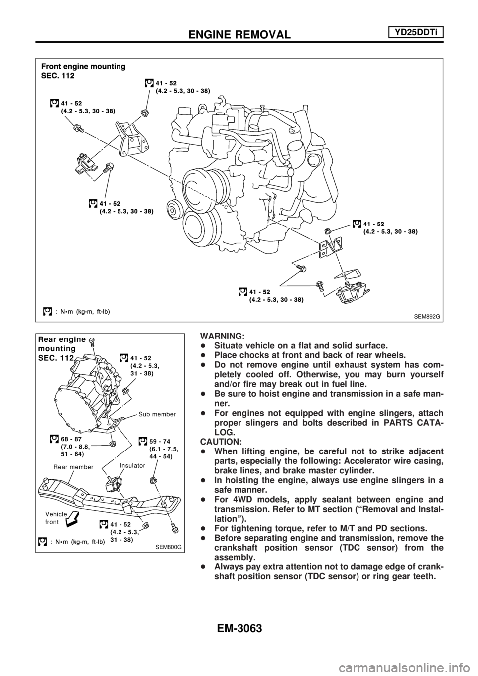
WARNING:
+Situate vehicle on a flat and solid surface.
+Place chocks at front and back of rear wheels.
+Do not remove engine until exhaust system has com-
pletely cooled off. Otherwise, you may burn yourself
and/or fire may break out in fuel line.
+Be sure to hoist engine and transmission in a safe man-
ner.
+For engines not equipped with engine slingers, attach
proper slingers and bolts described in PARTS CATA-
LOG.
CAUTION:
+When lifting engine, be careful not to strike adjacent
parts, especially the following: Accelerator wire casing,
brake lines, and brake master cylinder.
+In hoisting the engine, always use engine slingers in a
safe manner.
+For 4WD models, apply sealant between engine and
transmission. Refer to MT section (ªRemoval and Instal-
lationº).
+For tightening torque, refer to M/T and PD sections.
+Before separating engine and transmission, remove the
crankshaft position sensor (TDC sensor) from the
assembly.
+Always pay extra attention not to damage edge of crank-
shaft position sensor (TDC sensor) or ring gear teeth.
SEM892G
SEM800G
ENGINE REMOVALYD25DDTi
EM-3063
Page 1062 of 1306
A
A/C relay ..................................... HA-3019, 3029
A/C trouble diagnoses (auto A/C) ......... HA-3020
A/C trouble diagnoses
(manual A/C) ........................... HA-3004, 3020
A/C, A - Wiring diagram ........................ HA-3021
A/C, M - Wiring diagram ............. HA-3006, 3009
A/T IND - Wiring diagram ...................... EL-3100
AAC/V - Wiring diagram ....................... EC-3298
ABS - Wiring diagram ................. BR-3003, 3010
AT indicator lamp .................................. EL-3100
Accelerator control system .................... FE-3002
Accelerator position sensor ........ EC-3515, 3516
Air bag disposal .................................... RS-3011
Air bag ................................................... RS-3003
Air cleaner filter replacement ..... MA-3010, 3019
Air conditioner cut control . EC-3028, 3413, 3414
Air flow meter - See Mass air flow
sensor ................................................ EC-3151
Alternator ............................................... EL-3022
Angular tightening application .............. EM-3003
Antenna ................................................. EL-3115
Anti-lock brake system - Wiring
diagram ......................... BR-3002, 3003, 3009
Auxiliary air control (AAC) valve ........... EC-3295
B
BACK/L - Wiring diagram ...................... EL-3044
BOOST - Wiring diagram ....................................
Back-up lamp ......................................... EL-3044
Basic inspection ................ EC-3086, 3444, 3445
Battery ................................................... EL-3013
Bumper, front ....................................... BT-3002
C
CHARGE - Wiring diagram ................... EL-3018
CIGAR - Wiring diagram ....................... EL-3110
CKPS - Wiring diagram .............. EC-3266, 3351
CLOCK - Wiring diagram ...................... EL-3111
CMPS - Wiring diagram ........................ EC-3273
CONSULT for engine ....... EC-3070, 3434, 3435
Camshaft inspection ............................. EM-3050
Camshaft position sensor (CMPS) ....... EC-3270
Canister - See EVAP canister .............. EC-3029
Center case (Transfer) .......................... TF-3003
Charging system .................................... EL-3018
Cigarette lighter ..................................... EL-3110
Clock ...................................................... EL-3111
Closed throttle position switch ............. EC-3301
Collision diagnosis ................................ RS-3037
Combination lamp, front, removal and
installation .......................................... BT-3002
Combination meter ................................ EL-3056
Compression pressure ......................... EM-3013
Connecting rod bearing clearance ....... EM-3077Connecting rod bushing clearance ....... EM-3080
Connecting rod ..................................... EM-3072
Coolant replacement ............................ MA-3014
Cooling circuit (engine) ......................... LC-3010
Cooling fan control system ......... LC-3002, 3017
Cooling fan control ........... EC-3344, 3489, 3490
Cooling fan ............................................ LC-3016
Counter gear (Transfer) ......................... TF-3004
Crank angle sensor built into
distributor - See Camshaft position
sensor ................................................ EC-3270
Crankcase emission control system -
See Positive crankcase
ventilation ...................... EC-3032, 3414, 3415
Crankcase ventilation system - See
Positive crankcase
ventilation ...................... EC-3032, 3414, 3415
Crankshaft position sensor (OBD) cog
chipping ............................................. EC-3349
Crankshaft position sensor (OBD) ........ EC-3264
Crankshaft position sensor
(TDC) ...................................... EC-3534, 3535
Crankshaft ............................................ EM-3075
Cylinder block ....................................... EM-3066
Cylinder head ....................................... EM-3046
D
DEF - Wiring diagram ............................ EL-3112
DIMDIP - Wiring diagram ...................... EL-3033
DTC P0121 TP Sensor ........................ EC-3170
DTC work support ................................. EC-3078
DTRL - Wiring diagram ......................... EL-3029
Data link connector for
Consult .......................... EC-3033, 3434, 3435
Daytime light system ............................. EL-3029
Detonation sensor - See Knock
sensor ................................................ EC-3260
Diagnosis sensor unit ........................... RS-3005
Diagnostic trouble code (DTC) for
OBD system .................. EC-3009, 3428, 3429
Diagnostic trouble code (DTC) inspec-
tion priority chart ............................... EC-3100
Dim-dip lamp system ............................. EL-3033
Distributor ignition (DI) system ............. EC-3026
Distributor .............................................. EC-3026
Drive belt inspection ............................. MA-3011
Drive chain (Transfer) ............................ TF-3004
E
ECCS-D control
module ......... EC-3595, 3594, 3598, 3599, 3463,
3464, 3501, 3502, 3581, 3582,
3583, 3584, 3585, 3586
ECM input/output signal ... EC-3110, 3463, 3464
ECTS - Wiring diagram ......................... EC-3167
EGR - Wiring diagram ................ EC-3607, 3608
ALPHABETICAL INDEX
IDX-3002