2001 NISSAN PICK-UP compression ratio
[x] Cancel search: compression ratioPage 60 of 1306

SEF500V
Fast Idle Cam (FIC)
COMPONENT DESCRIPTIONNEEC0502The FIC is installed on the throttle body to maintain adequate
engine speed while the engine is cold. It is operated by a volumet-
ric change in wax located inside the thermo-element. The thermo-
element is operated by engine coolant temperature.
For inspection refer to ªTROUBLE DIAGNOSIS-BASIC
INSPECTIONº, ªBasic Inspectionº, EC-3086.
Idle Speed/Ignition Timing/Idle Mixture Ratio
Adjustment
NEEC0028PREPARATIONNEEC0028S05+Make sure that the following parts are in good order.
a)Battery
b)Ignition system
c)Engine oil and coolant levels
d)Fuses
e)ECM harness connector
f)Vacuum hoses
g)Air intake system
(Oil filler cap, oil level gauge, etc.)
h)Fuel pressure
i)Engine compression
j)Throttle valve
k)EVAP system
+On models equipped with air conditioner, checks should be carried out while the air conditioner is
ªOFFº.
+When measuring ªCOº percentage, insert probe more than 40 cm (15.7 in) into tail pipe.
+Turn off headlamps, heater blower.
+Keep front wheels pointed straight ahead.
BASIC SERVICE PROCEDUREKA24DE (EURO OBD)
Fast Idle Cam (FIC)
EC-3035
Page 276 of 1306
On Board Diagnosis LogicNEEC0202When a misfire occurs, engine speed will fluctuate. If the engine speed fluctuates enough to cause the CKP
sensor signal to vary, the ECM can determine that a misfire is occurring.
Sensor Input Signal to ECM ECM function
Crankshaft position sensor (OBD) Engine speed On board diagnosis of misfire
The misfire detection logic consists of the following two conditions.
1. One Trip Detection Logic (Three Way Catalyst Damage)
On the first trip that a misfire condition occurs that can damage the three way catalyst (TWC) due to
overheating, the MI will blink.
When a misfire condition occurs, the ECM monitors the CKP sensor signal every 200 engine revolutions
for a change.
When the misfire condition decreases to a level that will not damage the TWC, the MI will turn off.
If another misfire condition occurs that can damage the TWC on a second trip, the MI will blink.
When the misfire condition decreases to a level that will not damage the TWC, the MI will remain on.
If another misfire condition occurs that can damage the TWC, the MI will begin to blink again.
2. Two Trip Detection Logic (Exhaust quality deterioration)
For misfire conditions that will not damage the TWC (but will affect vehicle emissions), the MI will only light
when the misfire is detected on a second trip. During this condition, the ECM monitors the CKP sensor
signal every 1,000 engine revolutions.
A misfire malfunction can be detected on any one cylinder or on multiple cylinders.
DTC No. Malfunction is detected when ... Check Items (Possible Cause)
P0300
0300+Multiple cylinders misfire.+Improper spark plug
+Insufficient compression
+Incorrect fuel pressure
+The injector circuit is open or shorted
+Injectors
+Intake air leak
+The ignition secondary circuit is open or shorted
+Lack of fuel
+Drive plate/Flywheel
+Heated oxygen sensor 1
+Incorrect distributor rotor P0301
0301+No. 1 cylinder misfires.
P0302
0302+No. 2 cylinder misfires.
P0303
0303+No. 3 cylinder misfires.
P0304
0304+No. 4 cylinder misfires.
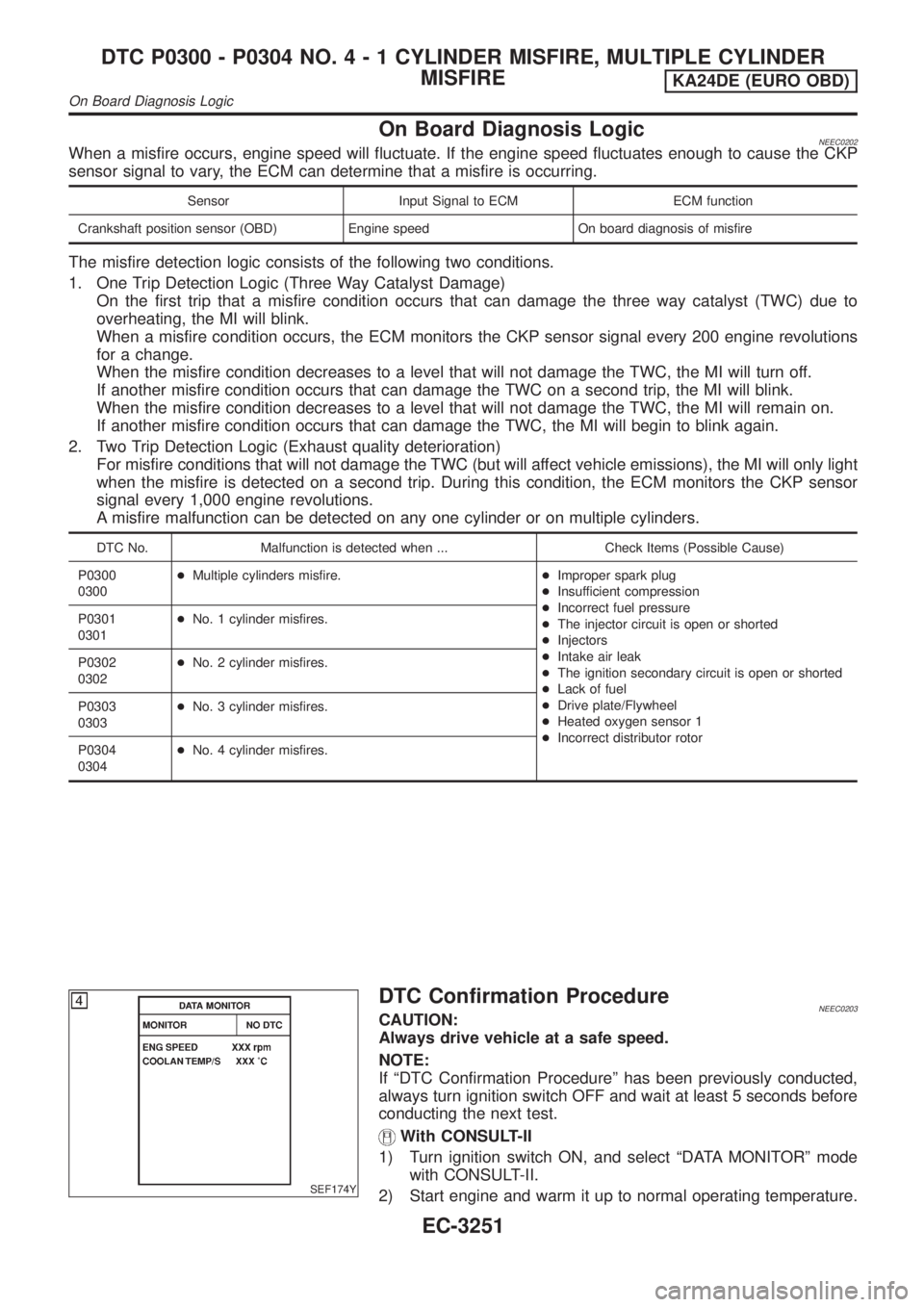
SEF174Y
DTC Confirmation ProcedureNEEC0203CAUTION:
Always drive vehicle at a safe speed.
NOTE:
If ªDTC Confirmation Procedureº has been previously conducted,
always turn ignition switch OFF and wait at least 5 seconds before
conducting the next test.
With CONSULT-II
1) Turn ignition switch ON, and select ªDATA MONITORº mode
with CONSULT-II.
2) Start engine and warm it up to normal operating temperature.
DTC P0300 - P0304 NO.4-1CYLINDER MISFIRE, MULTIPLE CYLINDER
MISFIRE
KA24DE (EURO OBD)
On Board Diagnosis Logic
EC-3251
Page 475 of 1306
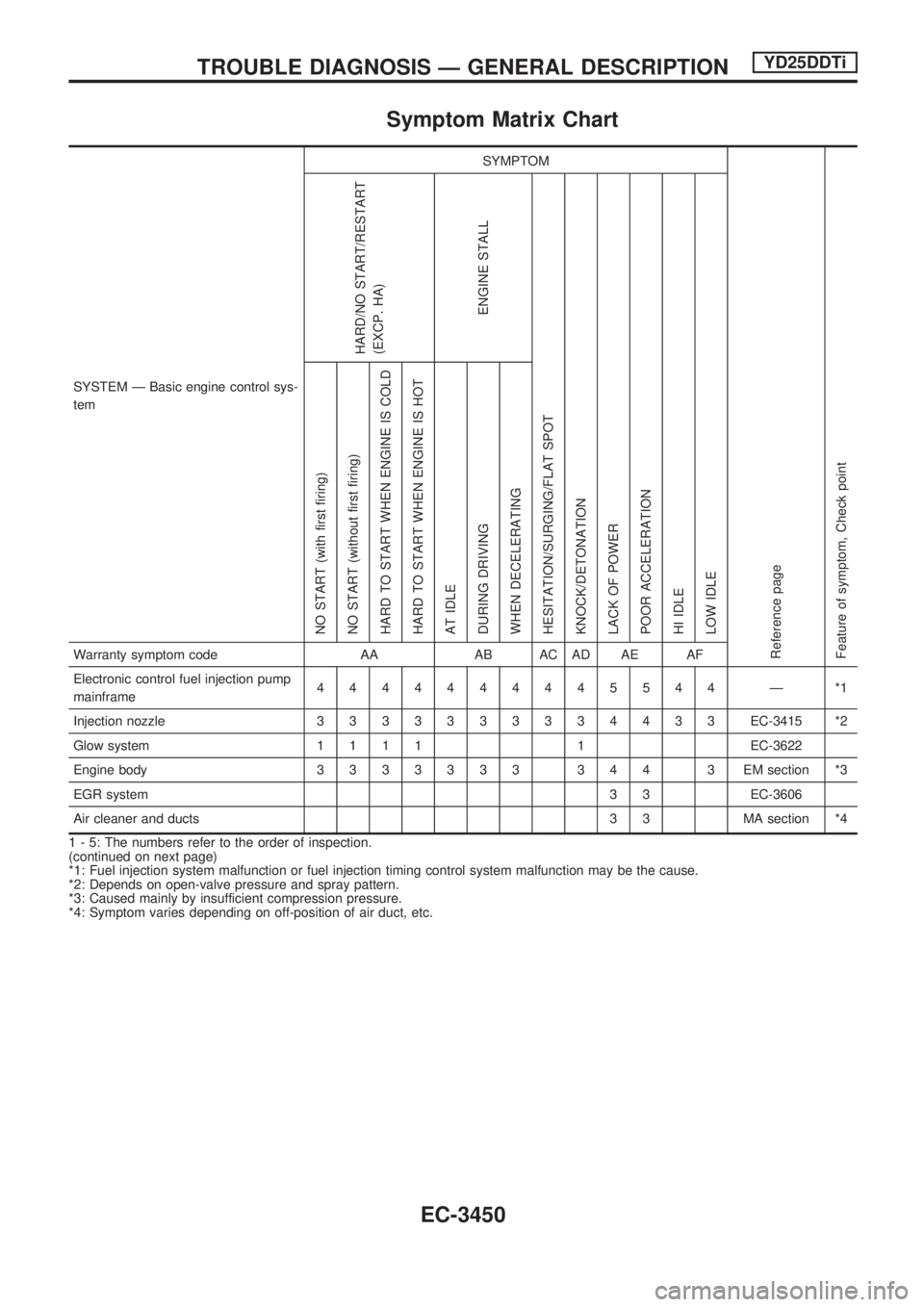
Symptom Matrix Chart
SYSTEM Ð Basic engine control sys-
temSYMPTOM
Reference page
Feature of symptom, Check pointHARD/NO START/RESTART
(EXCP. HA)
ENGINE STALL
HESITATION/SURGING/FLAT SPOT
KNOCK/DETONATION
LACK OF POWER
POOR ACCELERATION
HI IDLE
LOW IDLE NO START (with first firing)
NO START (without first firing)
HARD TO START WHEN ENGINE IS COLD
HARD TO START WHEN ENGINE IS HOT
AT IDLE
DURING DRIVING
WHEN DECELERATINGWarranty symptom code AA AB AC AD AE AF
Electronic control fuel injection pump
mainframe4444444445544 Ð *1
Injection nozzle3333333334433EC-3415 *2
Glow system1111 1EC-3622
Engine body3333333 344 3 EMsection *3
EGR system3 3 EC-3606
Air cleaner and ducts 3 3 MA section *4
1 - 5: The numbers refer to the order of inspection.
(continued on next page)
*1: Fuel injection system malfunction or fuel injection timing control system malfunction may be the cause.
*2: Depends on open-valve pressure and spray pattern.
*3: Caused mainly by insufficient compression pressure.
*4: Symptom varies depending on off-position of air duct, etc.
TROUBLE DIAGNOSIS Ð GENERAL DESCRIPTIONYD25DDTi
EC-3450
Page 476 of 1306
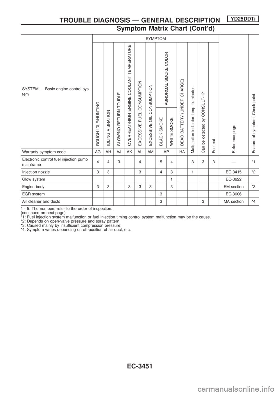
SYSTEM Ð Basic engine control sys-
temSYMPTOM
Reference page
Feature of symptom, Check pointROUGH IDLE/HUNTING
IDLING VIBRATION
SLOW/NO RETURN TO IDLE
OVERHEAT/HIGH ENGINE COOLANT TEMPERATURE
EXCESSIVE FUEL CONSUMPTION
EXCESSIVE OIL CONSUMPTION
ABNORMAL SMOKE COLOR
DEAD BATTERY (UNDER CHARGE)
Malfunction indicator lamp illuminates.
Can be detected by CONSULT-II?
Fuel cutBLACK SMOKE
WHITE SMOKEWarranty symptom code AG AH AJ AK AL AM AP HA
Electronic control fuel injection pump
mainframe443 4 54 333 Ð *1
Injection nozzle 3 3 3 4 3 1 EC-3415 *2
Glow system 1 EC-3622
Engine body 3 3 3 3 3 3 EM section *3
EGR system 3 EC-3606
Air cleaner and ducts 3 3 MA section *4
1 - 5: The numbers refer to the order of inspection.
(continued on next page)
*1: Fuel injection system malfunction or fuel injection timing control system malfunction may be the cause.
*2: Depends on open-valve pressure and spray pattern.
*3: Caused mainly by insufficient compression pressure.
*4: Symptom varies depending on off-position of air duct, etc.
TROUBLE DIAGNOSIS Ð GENERAL DESCRIPTIONYD25DDTi
Symptom Matrix Chart (Cont'd)
EC-3451
Page 878 of 1306
ENGINE MECHANICAL
SECTION
EM
MODIFICATION NOTICE:
+KA24DE engine information has been added for Europe.
For information not included here, refer to information for KA24DE engine in D22 Supplement-II Service
Manual (SM9E-D22BE0E).
+YD25DDTi engine has newly been added.
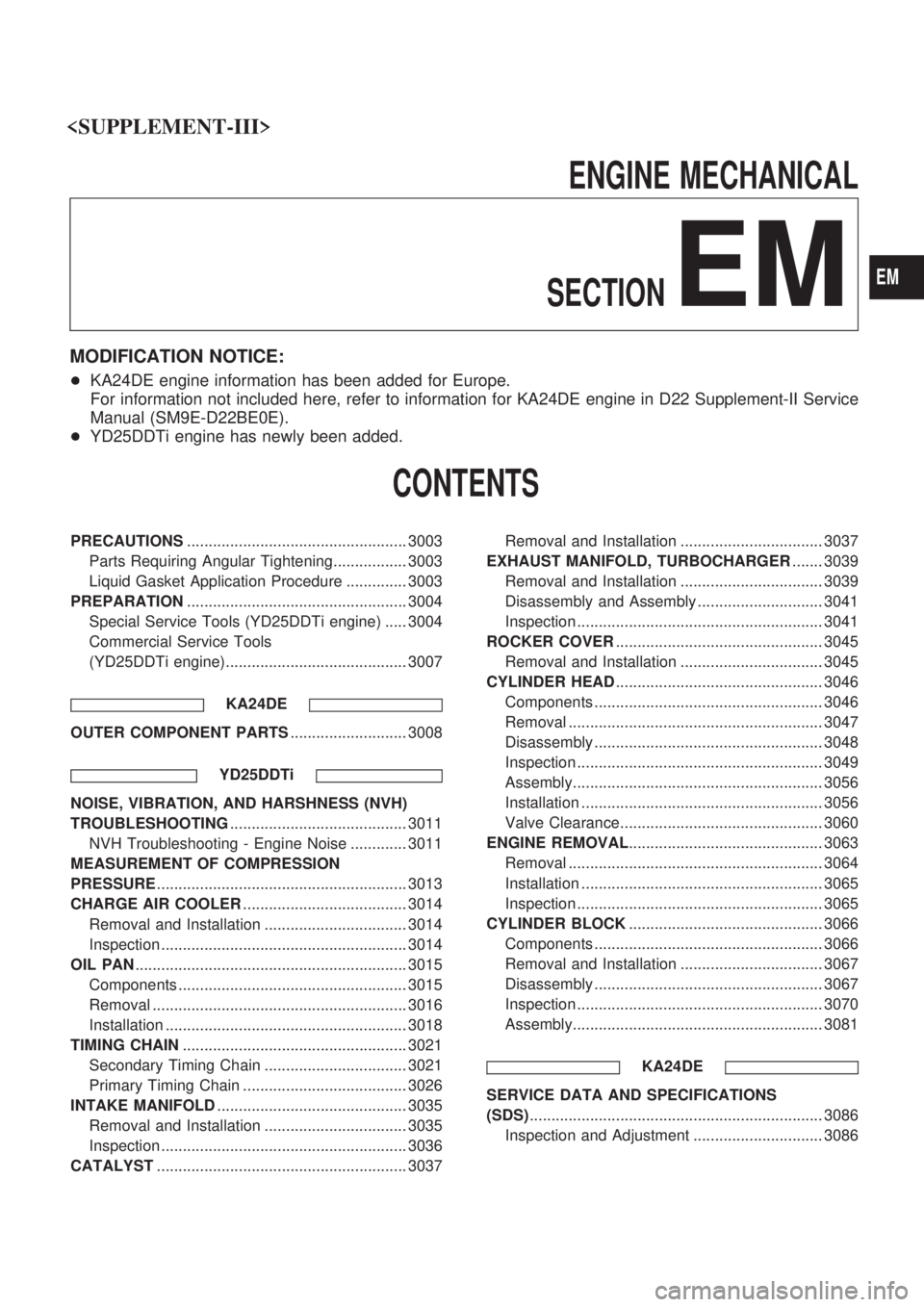
CONTENTS
PRECAUTIONS................................................... 3003
Parts Requiring Angular Tightening................. 3003
Liquid Gasket Application Procedure .............. 3003
PREPARATION................................................... 3004
Special Service Tools (YD25DDTi engine) ..... 3004
Commercial Service Tools
(YD25DDTi engine).......................................... 3007
KA24DE
OUTER COMPONENT PARTS........................... 3008
YD25DDTi
NOISE, VIBRATION, AND HARSHNESS (NVH)
TROUBLESHOOTING......................................... 3011
NVH Troubleshooting - Engine Noise ............. 3011
MEASUREMENT OF COMPRESSION
PRESSURE.......................................................... 3013
CHARGE AIR COOLER...................................... 3014
Removal and Installation ................................. 3014
Inspection ......................................................... 3014
OIL PAN............................................................... 3015
Components ..................................................... 3015
Removal ........................................................... 3016
Installation ........................................................ 3018
TIMING CHAIN.................................................... 3021
Secondary Timing Chain ................................. 3021
Primary Timing Chain ...................................... 3026
INTAKE MANIFOLD............................................ 3035
Removal and Installation ................................. 3035
Inspection ......................................................... 3036
CATALYST.......................................................... 3037Removal and Installation ................................. 3037
EXHAUST MANIFOLD, TURBOCHARGER....... 3039
Removal and Installation ................................. 3039
Disassembly and Assembly ............................. 3041
Inspection ......................................................... 3041
ROCKER COVER................................................ 3045
Removal and Installation ................................. 3045
CYLINDER HEAD................................................ 3046
Components ..................................................... 3046
Removal ........................................................... 3047
Disassembly ..................................................... 3048
Inspection ......................................................... 3049
Assembly.......................................................... 3056
Installation ........................................................ 3056
Valve Clearance............................................... 3060
ENGINE REMOVAL............................................. 3063
Removal ........................................................... 3064
Installation ........................................................ 3065
Inspection ......................................................... 3065
CYLINDER BLOCK............................................. 3066
Components ..................................................... 3066
Removal and Installation ................................. 3067
Disassembly ..................................................... 3067
Inspection ......................................................... 3070
Assembly.......................................................... 3081
KA24DE
SERVICE DATA AND SPECIFICATIONS
(SDS).................................................................... 3086
Inspection and Adjustment .............................. 3086
EM
Page 890 of 1306
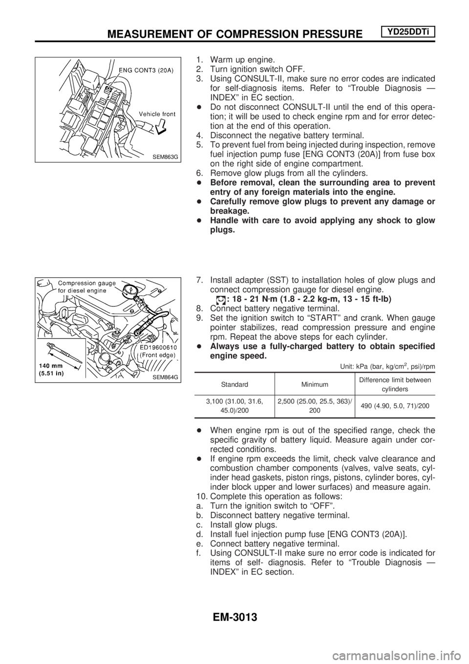
1. Warm up engine.
2. Turn ignition switch OFF.
3. Using CONSULT-II, make sure no error codes are indicated
for self-diagnosis items. Refer to ªTrouble Diagnosis Ð
INDEXº in EC section.
+Do not disconnect CONSULT-II until the end of this opera-
tion; it will be used to check engine rpm and for error detec-
tion at the end of this operation.
4. Disconnect the negative battery terminal.
5. To prevent fuel from being injected during inspection, remove
fuel injection pump fuse [ENG CONT3 (20A)] from fuse box
on the right side of engine compartment.
6. Remove glow plugs from all the cylinders.
+Before removal, clean the surrounding area to prevent
entry of any foreign materials into the engine.
+Carefully remove glow plugs to prevent any damage or
breakage.
+Handle with care to avoid applying any shock to glow
plugs.
7. Install adapter (SST) to installation holes of glow plugs and
connect compression gauge for diesel engine.
:18-21Nzm (1.8 - 2.2 kg-m, 13 - 15 ft-lb)
8. Connect battery negative terminal.
9. Set the ignition switch to ªSTARTº and crank. When gauge
pointer stabilizes, read compression pressure and engine
rpm. Repeat the above steps for each cylinder.
+Always use a fully-charged battery to obtain specified
engine speed.
Unit: kPa (bar, kg/cm2, psi)/rpm
Standard MinimumDifference limit between
cylinders
3,100 (31.00, 31.6,
45.0)/2002,500 (25.00, 25.5, 363)/
200490 (4.90, 5.0, 71)/200
+When engine rpm is out of the specified range, check the
specific gravity of battery liquid. Measure again under cor-
rected conditions.
+If engine rpm exceeds the limit, check valve clearance and
combustion chamber components (valves, valve seats, cyl-
inder head gaskets, piston rings, pistons, cylinder bores, cyl-
inder block upper and lower surfaces) and measure again.
10. Complete this operation as follows:
a. Turn the ignition switch to ªOFFº.
b. Disconnect battery negative terminal.
c. Install glow plugs.
d. Install fuel injection pump fuse [ENG CONT3 (20A)].
e. Connect battery negative terminal.
f. Using CONSULT-II make sure no error code is indicated for
items of self- diagnosis. Refer to ªTrouble Diagnosis Ð
INDEXº in EC section.
SEM863G
SEM864G
MEASUREMENT OF COMPRESSION PRESSUREYD25DDTi
EM-3013
Page 965 of 1306
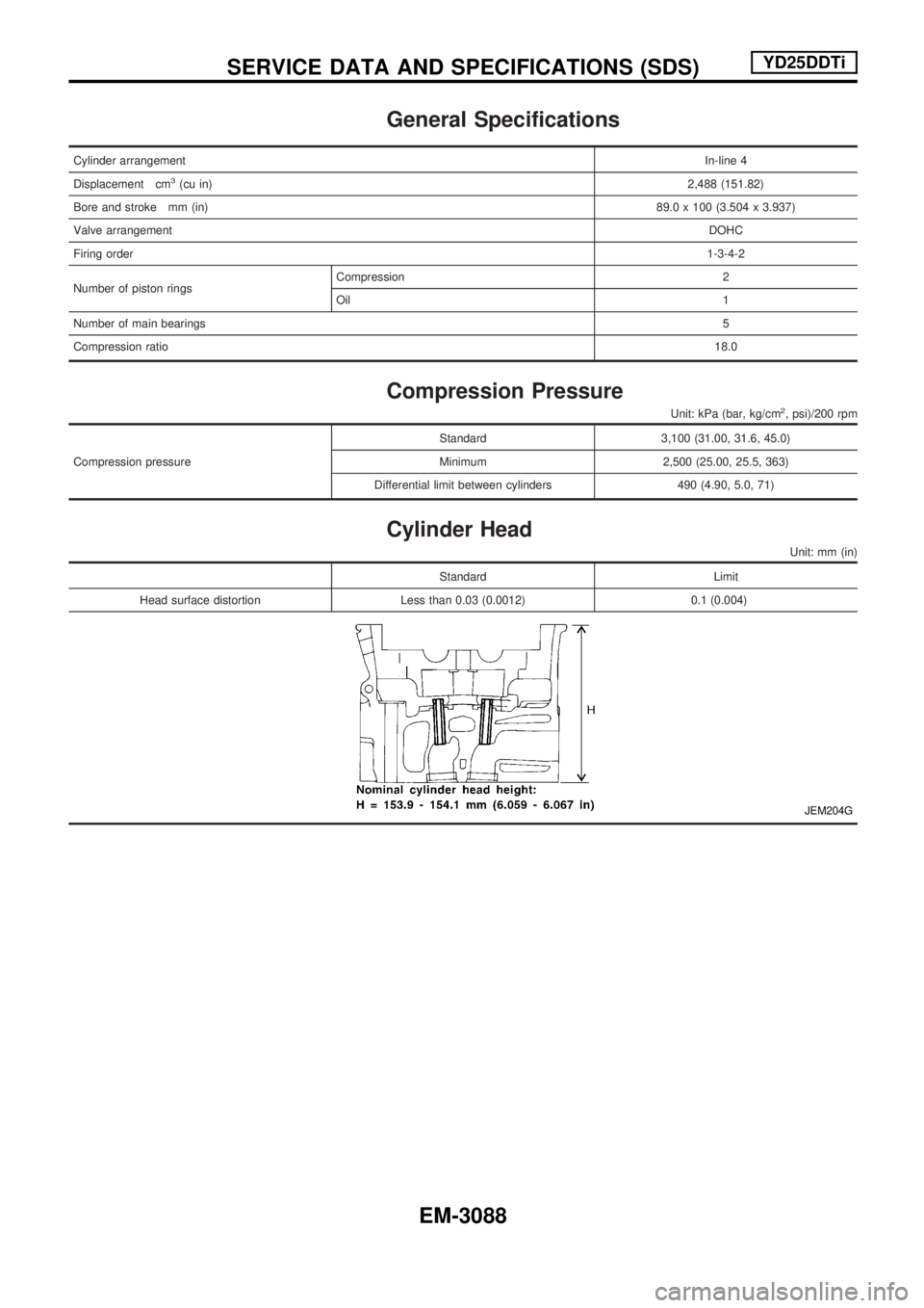
General Specifications
Cylinder arrangementIn-line 4
Displacement cm
3(cu in) 2,488 (151.82)
Bore and stroke mm (in) 89.0 x 100 (3.504 x 3.937)
Valve arrangement DOHC
Firing order 1-3-4-2
Number of piston rings Compression 2
Oil
1
Number of main bearings 5
Compression ratio 18.0
Compression Pressure
Unit: kPa (bar, kg/cm2, psi)/200 rpm
Compression pressureStandard 3,100 (31.00, 31.6, 45.0)
Minimum 2,500 (25.00, 25.5, 363)
Differential limit between cylinders 490 (4.90, 5.0, 71)
Cylinder Head
Unit: mm (in)
Standard Limit
HeadsurfacedistortionLessthan0.03(0.0012)0.1 (0.004)
JEM204G
SERVICE DATA AND SPECIFICATIONS (SDS)YD25DDTi
EM-3088