2001 NISSAN PICK-UP heating
[x] Cancel search: heatingPage 29 of 1306
DTC Confirmation Procedure .......................... 3308
Diagnostic Procedure....................................... 3309
DTC P1143 HO2S1.............................................. 3310
Component Description ................................... 3310
CONSULT-II Reference Value in Data Monitor
Mode ................................................................ 3310
ECM Terminals and Reference Value ............. 3310
On Board Diagnosis Logic ............................... 3311
DTC Confirmation Procedure .......................... 3311
Overall Function Check ................................... 3312
Diagnostic Procedure....................................... 3312
DTC P1144 HO2S1.............................................. 3317
Component Description ................................... 3317
CONSULT-II Reference Value in Data Monitor
Mode ................................................................ 3317
ECM Terminals and Reference Value ............. 3317
On Board Diagnosis Logic ............................... 3318
DTC Confirmation Procedure .......................... 3318
Overall Function Check ................................... 3319
Diagnostic Procedure....................................... 3319
DTC P1146 HO2S2.............................................. 3324
Component Description ................................... 3324
CONSULT-II Reference Value in Data Monitor
Mode ................................................................ 3324
ECM Terminals and Reference Value ............. 3324
On Board Diagnosis Logic ............................... 3324
DTC Confirmation Procedure .......................... 3325
Overall Function Check ................................... 3326
Wiring Diagram ................................................ 3327
Diagnostic Procedure....................................... 3328
DTC P1147 HO2S2.............................................. 3334
Component Description ................................... 3334
CONSULT-II Reference Value in Data Monitor
Mode ................................................................ 3334
ECM Terminals and Reference Value ............. 3334
On Board Diagnosis Logic ............................... 3334
DTC Confirmation Procedure .......................... 3335
Overall Function Check ................................... 3336
Wiring Diagram ................................................ 3337
Diagnostic Procedure....................................... 3338
DTC P1217 Engine Over Temperature............. 3344
On Board Diagnosis Logic ............................... 3344
Overall Function Check ................................... 3344
Diagnostic Procedure....................................... 3345
Main 11 Causes of Overheating ...................... 3348
DTC P1336 CKP Sensor (OBD)......................... 3349
Component Description ................................... 3349
ECM Terminals and Reference Value ............. 3349
On Board Diagnosis Logic ............................... 3350
DTC Confirmation Procedure .......................... 3350
Wiring Diagram ................................................ 3351
Diagnostic Procedure....................................... 3352
DTC P1706 PNP Switch..................................... 3355
Component Description ................................... 3355CONSULT-II Reference Value in Data Monitor
Mode ................................................................ 3355
ECM Terminals and Reference Value ............. 3355
On Board Diagnosis Logic ............................... 3355
DTC Confirmation Procedure .......................... 3356
Overall Function Check ................................... 3357
Wiring Diagram ................................................ 3358
Diagnostic Procedure....................................... 3359
Ignition Signal..................................................... 3361
Component Description ................................... 3361
CONSULT-II Reference Value in Data Monitor
Mode ................................................................ 3361
ECM Terminals and Reference Value ............. 3362
Wiring Diagram ................................................ 3363
Diagnostic Procedure....................................... 3365
Injector................................................................. 3369
Component Description ................................... 3369
ECM Terminals and Reference Value ............. 3369
Wiring Diagram ................................................ 3370
Diagnostic Procedure....................................... 3371
Start Signal......................................................... 3374
CONSULT-II Reference Value in Data Monitor
Mode ................................................................ 3374
ECM Terminals and Reference Value ............. 3374
Wiring Diagram ................................................ 3375
Diagnostic Procedure....................................... 3376
Fuel Pump........................................................... 3378
System Description .......................................... 3378
Component Description ................................... 3378
CONSULT-II Reference Value in Data Monitor
Mode ................................................................ 3378
ECM Terminals and Reference Value ............. 3379
Wiring Diagram ................................................ 3380
Diagnostic Procedure....................................... 3381
Power Steering Oil Pressure Switch................ 3385
Component Description ................................... 3385
CONSULT-II Reference Value in Data Monitor
Mode ................................................................ 3385
ECM Terminals and Reference Value ............. 3385
Wiring Diagram ................................................ 3386
Diagnostic Procedure....................................... 3387
IACV-FICD Solenoid Valve................................ 3389
Component Description ................................... 3389
ECM Terminals and Reference Value ............. 3389
Wiring Diagram ................................................ 3390
Diagnostic Procedure....................................... 3392
MI & Data Link Connectors............................... 3396
Wiring Diagram ................................................ 3396
Service Data and Specifications (SDS)............ 3398
Fuel Pressure Regulator .................................. 3398
Idle Speed and Ignition Timing ........................ 3398
Ignition Coil ...................................................... 3398
Mass Air Flow Sensor...................................... 3398
Engine Coolant Temperature Sensor .............. 3398
EC-3004
Page 30 of 1306
Fuel Pump........................................................ 3398
IACV-AAC Valve .............................................. 3398
Injector ............................................................. 3398
Throttle Position Sensor .................................. 3399
Heated Oxygen Sensor 1 Heater .................... 3399
Calculated Load Value..................................... 3399
Intake Air Temperature Sensor ....................... 3399
Heated Oxygen Sensor 2 Heater .................... 3399
Crankshaft Position Sensor (OBD) .................. 3399
YD25DDTi
TROUBLE DIAGNOSIS - INDEX........................ 3400
Alphabetical & Numerical Index for DTC......... 3400
PRECAUTIONS................................................... 3402
Precautions ...................................................... 3402
ENGINE AND EMISSION CONTROL OVERALL
SYSTEM............................................................... 3405
Engine Control Component Parts Location ..... 3405
Circuit Diagram ................................................ 3408
System Diagram .............................................. 3409
System Chart ................................................... 3410
ENGINE AND EMISSION BASIC CONTROL
SYSTEM DESCRIPTION..................................... 3411
Fuel Injection Control System.......................... 3411
Fuel Injection Timing Control System.............. 3413
Air Conditioning Cut Control ............................ 3413
Fuel Cut Control (at no load & high engine
speed) .............................................................. 3413
Crankcase Ventilation System ......................... 3414
BASIC SERVICE PROCEDURE......................... 3415
Injection Tube and Injection Nozzle ................ 3415
Electronic Control Fuel Injection Pump ........... 3419
Air Bleeding...................................................... 3426
Water Draining ................................................. 3426
Accelerator Position Sensor Idle Position
Learning ........................................................... 3427
ON BOARD DIAGNOSTIC SYSTEM
DESCRIPTION..................................................... 3428
DTC and MIL Detection Logic ......................... 3428
Diagnostic Trouble Code (DTC) ...................... 3428
Malfunction Indicator Lamp (MIL) .................... 3429
CONSULT-II ..................................................... 3434
TROUBLE DIAGNOSIS - INTRODUCTION........ 3440
Introduction ...................................................... 3440
Work Flow ........................................................ 3442
TROUBLE DIAGNOSIS - BASIC INSPECTION. 3444
Basic Inspection ............................................... 3444
TROUBLE DIAGNOSIS - GENERAL
DESCRIPTION..................................................... 3450
Symptom Matrix Chart ..................................... 3450
CONSULT-II Reference Value in Data Monitor
Mode ................................................................ 3460Major Sensor Reference Graph in Data
Monitor Mode ................................................... 3462
ECM Terminals and Reference Value ............. 3463
TROUBLE DIAGNOSIS FOR INTERMITTENT
INCIDENT............................................................. 3469
Description ....................................................... 3469
Diagnostic Procedure....................................... 3469
TROUBLE DIAGNOSIS FOR POWER SUPPLY3470
Main Power Supply and Ground Circuit .......... 3470
DTC 0103 COOLANT TEMP SEN...................... 3480
Description ....................................................... 3480
On Board Diagnosis Logic ............................... 3480
DTC Confirmation Procedure .......................... 3480
Wiring Diagram ................................................ 3481
Diagnostic Procedure....................................... 3482
DTC 0104 VEHICLE SPEED SEN...................... 3484
Description ....................................................... 3484
ECM Terminals and Reference Value ............. 3484
On Board Diagnosis Logic ............................... 3484
Overall Function Check ................................... 3485
Wiring Diagram ................................................ 3486
Diagnostic Procedure....................................... 3488
DTC 0208 OVER HEAT....................................... 3489
Description ....................................................... 3489
CONSULT-II Reference Value in Data Monitor
Mode ................................................................ 3489
ECM Terminals and Reference Value ............. 3490
On Board Diagnosis Logic ............................... 3490
Overall Function Check ................................... 3491
Wiring Diagram ................................................ 3492
Diagnostic Procedure....................................... 3493
Main 12 Causes of Overheating ...................... 3500
DTC 0301 ECM 2, DTC 901 ECM 12................. 3501
Description ....................................................... 3501
On Board Diagnosis Logic ............................... 3501
DTC Confirmation Procedure .......................... 3501
Diagnostic Procedure....................................... 3502
DTC 0401 INTAKE AIR TEMPERATURE
SENSOR.............................................................. 3503
Component Description ................................... 3503
On Board Diagnosis Logic ............................... 3503
DTC Confirmation Procedure .......................... 3503
Wiring Diagram ................................................ 3505
Diagnostic Procedure....................................... 3506
DTC 0402 P9zFUEL TEMP SEN......................... 3508
Description ....................................................... 3508
CONSULT-II Reference Value in Data Monitor
Mode ................................................................ 3509
ECM Terminals and Reference Value ............. 3509
On Board Diagnosis Logic ............................... 3510
DTC Confirmation Procedure .......................... 3510
Wiring Diagram ................................................ 3511
Diagnostic Procedure....................................... 3513
EC-3005
Page 276 of 1306
On Board Diagnosis LogicNEEC0202When a misfire occurs, engine speed will fluctuate. If the engine speed fluctuates enough to cause the CKP
sensor signal to vary, the ECM can determine that a misfire is occurring.
Sensor Input Signal to ECM ECM function
Crankshaft position sensor (OBD) Engine speed On board diagnosis of misfire
The misfire detection logic consists of the following two conditions.
1. One Trip Detection Logic (Three Way Catalyst Damage)
On the first trip that a misfire condition occurs that can damage the three way catalyst (TWC) due to
overheating, the MI will blink.
When a misfire condition occurs, the ECM monitors the CKP sensor signal every 200 engine revolutions
for a change.
When the misfire condition decreases to a level that will not damage the TWC, the MI will turn off.
If another misfire condition occurs that can damage the TWC on a second trip, the MI will blink.
When the misfire condition decreases to a level that will not damage the TWC, the MI will remain on.
If another misfire condition occurs that can damage the TWC, the MI will begin to blink again.
2. Two Trip Detection Logic (Exhaust quality deterioration)
For misfire conditions that will not damage the TWC (but will affect vehicle emissions), the MI will only light
when the misfire is detected on a second trip. During this condition, the ECM monitors the CKP sensor
signal every 1,000 engine revolutions.
A misfire malfunction can be detected on any one cylinder or on multiple cylinders.
DTC No. Malfunction is detected when ... Check Items (Possible Cause)
P0300
0300+Multiple cylinders misfire.+Improper spark plug
+Insufficient compression
+Incorrect fuel pressure
+The injector circuit is open or shorted
+Injectors
+Intake air leak
+The ignition secondary circuit is open or shorted
+Lack of fuel
+Drive plate/Flywheel
+Heated oxygen sensor 1
+Incorrect distributor rotor P0301
0301+No. 1 cylinder misfires.
P0302
0302+No. 2 cylinder misfires.
P0303
0303+No. 3 cylinder misfires.
P0304
0304+No. 4 cylinder misfires.
SEF174Y
DTC Confirmation ProcedureNEEC0203CAUTION:
Always drive vehicle at a safe speed.
NOTE:
If ªDTC Confirmation Procedureº has been previously conducted,
always turn ignition switch OFF and wait at least 5 seconds before
conducting the next test.
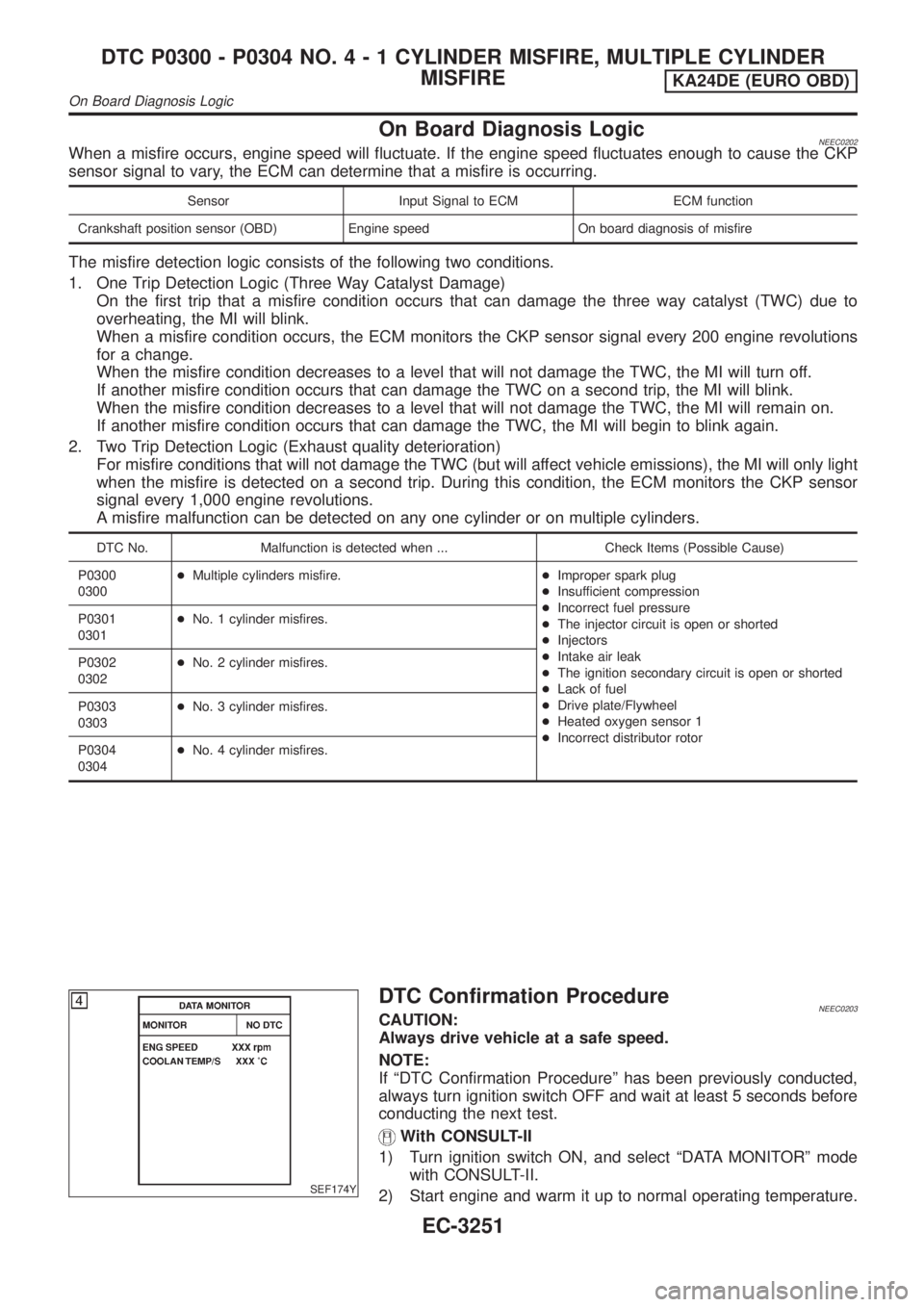
With CONSULT-II
1) Turn ignition switch ON, and select ªDATA MONITORº mode
with CONSULT-II.
2) Start engine and warm it up to normal operating temperature.
DTC P0300 - P0304 NO.4-1CYLINDER MISFIRE, MULTIPLE CYLINDER
MISFIRE
KA24DE (EURO OBD)
On Board Diagnosis Logic
EC-3251
Page 369 of 1306
On Board Diagnosis LogicNEEC1534If the cooling fan or another component in the cooling system malfunctions, engine coolant temperature will
rise.
When the engine coolant temperature reaches an abnormally high temperature condition, a malfunction is
indicated.
DTC No. Malfunction is detected when ...Check Items
(Possible Cause)
P1217
1217+Engine coolant temperature reaches an abnormally high
temperature.+Cooling fan (crankshaft driven)
Radiator hose
+Radiator
+Radiator cap
+Water pump
+Thermostat
+Engine coolant temperature sensor
For more information, refer to ªMAIN 11 CAUSES
OF OVERHEATINGº, EC-3348.
CAUTION:
When a malfunction is indicated, be sure to replace the coolant. Refer to MA section, ªChanging Engine
Coolantº. Also, replace the engine oil.
1) Fill radiator with coolant up to specified level with a filling speed of 2 liters per minute. Be sure
to use coolant with the proper mixture ratio. Refer to MA section, ªAnti-freeze Coolant Mixture
Ratioº.
2) After refilling coolant, run engine to ensure that no water-flow noise is emitted.
SEF621W
Overall Function CheckNEEC1535WARNING:
Never remove the radiator cap when the engine is hot. Serious
burns could be caused by high pressure fluid escaping from
the radiator.
Wrap a thick cloth around cap. Carefully remove the cap by
turning it a quarter turn to allow built-up pressure to escape.
Then turn the cap all the way off.
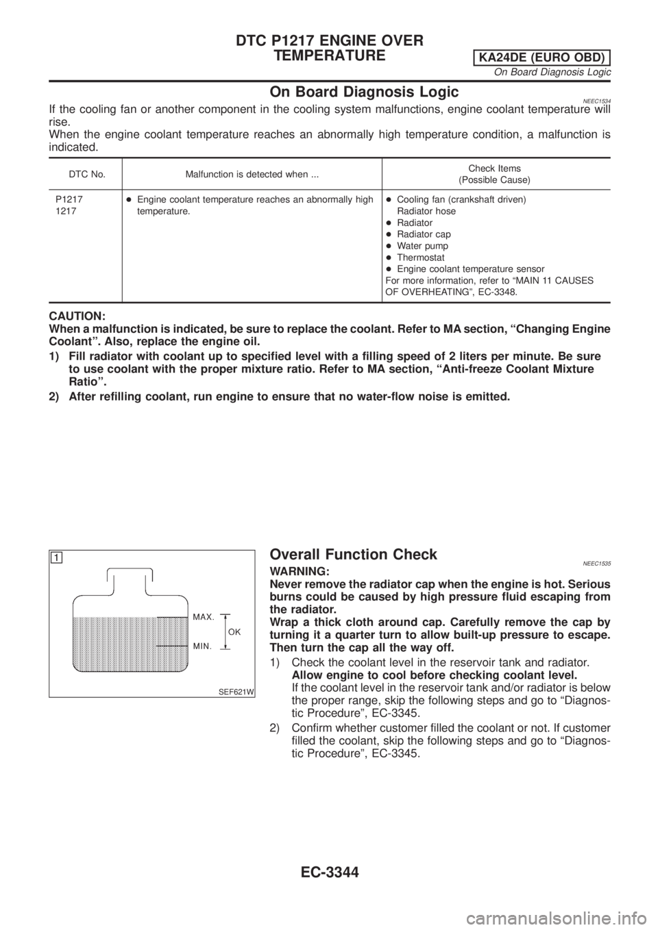
1) Check the coolant level in the reservoir tank and radiator.
Allow engine to cool before checking coolant level.
If the coolant level in the reservoir tank and/or radiator is below
the proper range, skip the following steps and go to ªDiagnos-
tic Procedureº, EC-3345.
2) Confirm whether customer filled the coolant or not. If customer
filled the coolant, skip the following steps and go to ªDiagnos-
tic Procedureº, EC-3345.
DTC P1217 ENGINE OVER
TEMPERATURE
KA24DE (EURO OBD)
On Board Diagnosis Logic
EC-3344
Page 372 of 1306
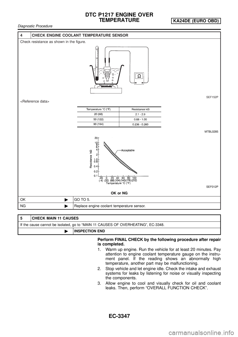
4 CHECK ENGINE COOLANT TEMPERATURE SENSOR
Check resistance as shown in the figure.
SEF152P
MTBL0285
SEF012P
OK or NG
OK©GO TO 5.
NG©Replace engine coolant temperature sensor.
5 CHECK MAIN 11 CAUSES
If the cause cannot be isolated, go to ªMAIN 11 CAUSES OF OVERHEATINGº, EC-3348.
©INSPECTION END
Perform FINAL CHECK by the following procedure after repair
is completed.
1. Warm up engine. Run the vehicle for at least 20 minutes. Pay
attention to engine coolant temperature gauge on the instru-
ment panel. If the reading shows an abnormally high
temperature, another part may be malfunctioning.
2. Stop vehicle and let engine idle. Check the intake and exhaust
systems for leaks by listening for noise or visually inspecting
the components.
3. Allow engine to cool and visually check for oil and coolant
leaks. Then, perform ªOVERALL FUNCTION CHECKº.
DTC P1217 ENGINE OVER
TEMPERATURE
KA24DE (EURO OBD)
Diagnostic Procedure
EC-3347
Page 373 of 1306
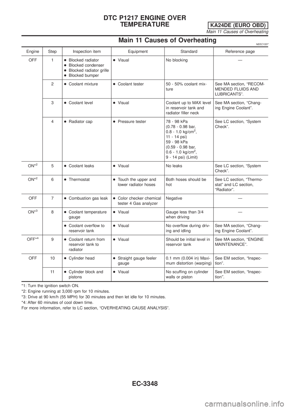
Main 11 Causes of OverheatingNEEC1537
Engine Step Inspection item Equipment Standard Reference page
OFF 1+Blocked radiator
+Blocked condenser
+Blocked radiator grille
+Blocked bumper+Visual No blocking Ð
2+Coolant mixture+Coolant tester 50 - 50% coolant mix-
tureSee MA section, ªRECOM-
MENDED FLUIDS AND
LUBRICANTSº.
3+Coolant level+Visual Coolant up to MAX level
in reservoir tank and
radiator filler neckSee MA section, ªChang-
ing Engine Coolantº.
4+Radiator cap+Pressure tester 78 - 98 kPa
(0.78 - 0.98 bar,
0.8 - 1.0 kg/cm
2,
11 - 14 psi)
59-98kPa
(0.59 - 0.98 bar,
0.6 - 1.0 kg/cm
2,
9 - 14 psi) (Limit)See LC section, ªSystem
Checkº.
ON*
25+Coolant leaks+Visual No leaks See LC section, ªSystem
Checkº.
ON*
26+Thermostat+Touch the upper and
lower radiator hosesBoth hoses should be
hotSee LC section, ªThermo-
statº and LC section,
ªRadiatorº.
OFF 7+Combustion gas leak+Color checker chemical
tester 4 Gas analyzerNegative Ð
ON*
38+Coolant temperature
gauge+Visual Gauge less than 3/4
when drivingÐ
+Coolant overflow to
reservoir tank+Visual No overflow during driv-
ing and idlingSee MA section, ªChang-
ing Engine Coolantº.
OFF*
49+Coolant return from
reservoir tank to
radiator+Visual Should be initial level in
reservoir tankSee MA section, ªENGINE
MAINTENANCEº.
OFF 10+Cylinder head+Straight gauge feeler
gauge0.1 mm (0.004 in) Maxi-
mum distortion (warping)See EM section, ªInspec-
tionº.
11+Cylinder block and
pistons+Visual No scuffing on cylinder
walls or pistonSee EM section, ªInspec-
tion².
*1: Turn the ignition switch ON.
*2: Engine running at 3,000 rpm for 10 minutes.
*3: Drive at 90 km/h (55 MPH) for 30 minutes and then let idle for 10 minutes.
*4: After 60 minutes of cool down time.
For more information, refer to LC section, ªOVERHEATING CAUSE ANALYSISº.
DTC P1217 ENGINE OVER
TEMPERATURE
KA24DE (EURO OBD)
Main 11 Causes of Overheating
EC-3348
Page 515 of 1306
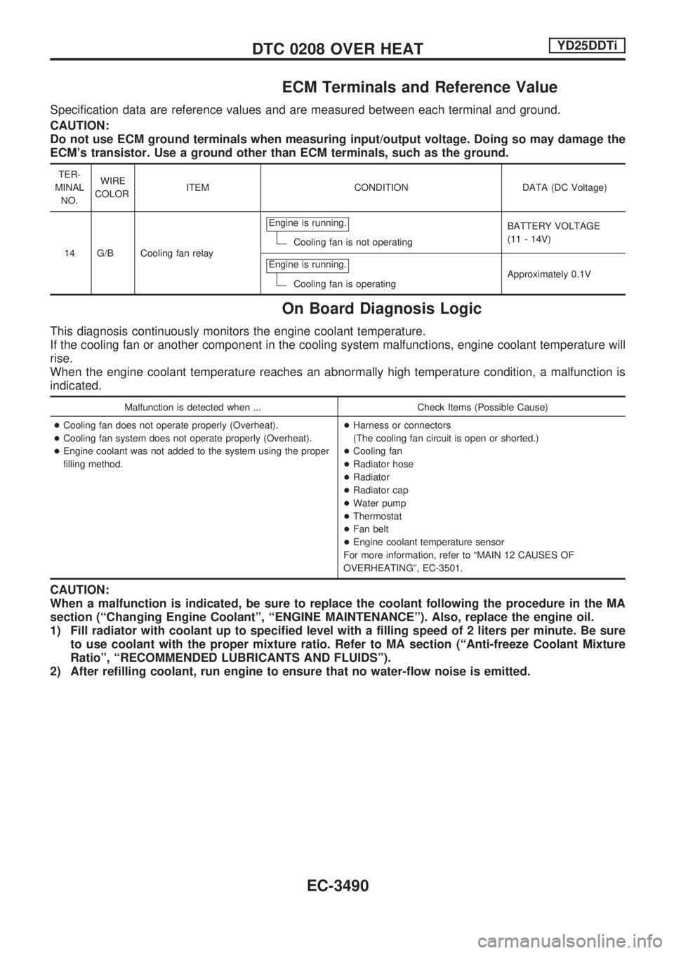
ECM Terminals and Reference Value
Specification data are reference values and are measured between each terminal and ground.
CAUTION:
Do not use ECM ground terminals when measuring input/output voltage. Doing so may damage the
ECM's transistor. Use a ground other than ECM terminals, such as the ground.
TER-
MINAL
NO.WIRE
COLORITEM CONDITION DATA (DC Voltage)
14 G/B Cooling fan relayEngine is running.
Cooling fan is not operatingBATTERY VOLTAGE
(11 - 14V)
Engine is running.
Cooling fan is operatingApproximately 0.1V
On Board Diagnosis Logic
This diagnosis continuously monitors the engine coolant temperature.
If the cooling fan or another component in the cooling system malfunctions, engine coolant temperature will
rise.
When the engine coolant temperature reaches an abnormally high temperature condition, a malfunction is
indicated.
Malfunction is detected when ... Check Items (Possible Cause)
+Cooling fan does not operate properly (Overheat).
+Cooling fan system does not operate properly (Overheat).
+Engine coolant was not added to the system using the proper
filling method.+Harness or connectors
(The cooling fan circuit is open or shorted.)
+Cooling fan
+Radiator hose
+Radiator
+Radiator cap
+Water pump
+Thermostat
+Fan belt
+Engine coolant temperature sensor
For more information, refer to ªMAIN 12 CAUSES OF
OVERHEATINGº, EC-3501.
CAUTION:
When a malfunction is indicated, be sure to replace the coolant following the procedure in the MA
section (ªChanging Engine Coolantº, ªENGINE MAINTENANCEº). Also, replace the engine oil.
1) Fill radiator with coolant up to specified level with a filling speed of 2 liters per minute. Be sure
to use coolant with the proper mixture ratio. Refer to MA section (ªAnti-freeze Coolant Mixture
Ratioº, ªRECOMMENDED LUBRICANTS AND FLUIDSº).
2) After refilling coolant, run engine to ensure that no water-flow noise is emitted.
DTC 0208 OVER HEATYD25DDTi
EC-3490
Page 525 of 1306
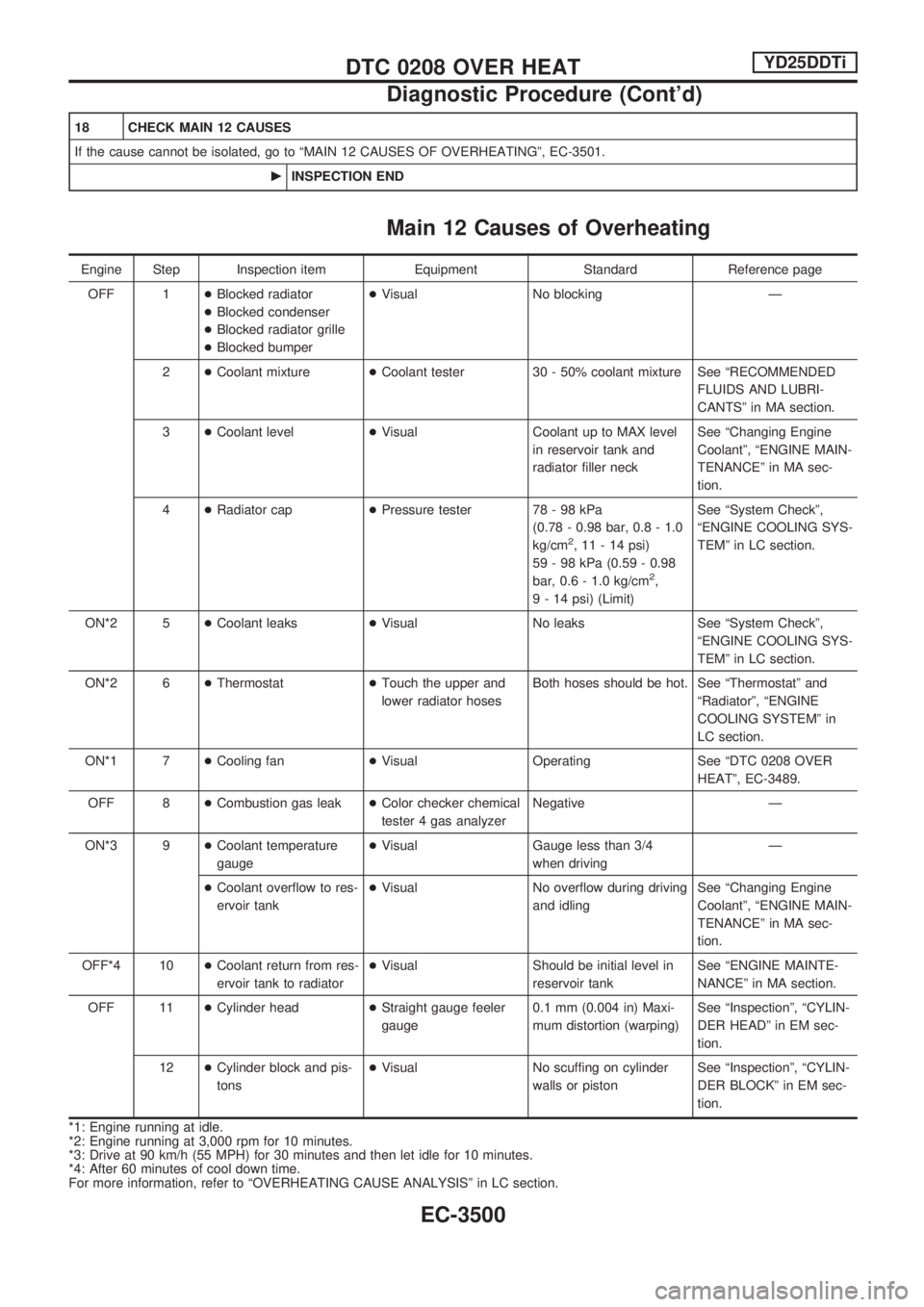
18 CHECK MAIN 12 CAUSES
If the cause cannot be isolated, go to ªMAIN 12 CAUSES OF OVERHEATINGº, EC-3501.
cINSPECTION END
Main 12 Causes of Overheating
Engine Step Inspection item Equipment Standard Reference page
OFF 1+Blocked radiator
+Blocked condenser
+Blocked radiator grille
+Blocked bumper+Visual No blocking Ð
2+Coolant mixture+Coolant tester 30 - 50% coolant mixture See ªRECOMMENDED
FLUIDS AND LUBRI-
CANTSº in MA section.
3+Coolant level+Visual Coolant up to MAX level
in reservoir tank and
radiator filler neckSee ªChanging Engine
Coolantº, ªENGINE MAIN-
TENANCEº in MA sec-
tion.
4+Radiator cap+Pressure tester 78 - 98 kPa
(0.78 - 0.98 bar, 0.8 - 1.0
kg/cm
2, 11 - 14 psi)
59 - 98 kPa (0.59 - 0.98
bar, 0.6 - 1.0 kg/cm
2,
9 - 14 psi) (Limit)See ªSystem Checkº,
ªENGINE COOLING SYS-
TEMº in LC section.
ON*2 5+Coolant leaks+Visual No leaks See ªSystem Checkº,
ªENGINE COOLING SYS-
TEMº in LC section.
ON*2 6+Thermostat+Touch the upper and
lower radiator hosesBoth hoses should be hot. See ªThermostatº and
ªRadiatorº, ªENGINE
COOLING SYSTEMº in
LC section.
ON*1 7+Cooling fan+Visual Operating See ªDTC 0208 OVER
HEATº, EC-3489.
OFF 8+Combustion gas leak+Color checker chemical
tester 4 gas analyzerNegative Ð
ON*3 9+Coolant temperature
gauge+Visual Gauge less than 3/4
when drivingÐ
+Coolant overflow to res-
ervoir tank+Visual No overflow during driving
and idlingSee ªChanging Engine
Coolantº, ªENGINE MAIN-
TENANCEº in MA sec-
tion.
OFF*4 10+Coolant return from res-
ervoir tank to radiator+Visual Should be initial level in
reservoir tankSee ªENGINE MAINTE-
NANCEº in MA section.
OFF 11+Cylinder head+Straight gauge feeler
gauge0.1 mm (0.004 in) Maxi-
mum distortion (warping)See ªInspectionº, ªCYLIN-
DER HEADº in EM sec-
tion.
12+Cylinder block and pis-
tons+Visual No scuffing on cylinder
walls or pistonSee ªInspectionº, ªCYLIN-
DER BLOCKº in EM sec-
tion.
*1: Engine running at idle.
*2: Engine running at 3,000 rpm for 10 minutes.
*3: Drive at 90 km/h (55 MPH) for 30 minutes and then let idle for 10 minutes.
*4: After 60 minutes of cool down time.
For more information, refer to ªOVERHEATING CAUSE ANALYSISº in LC section.
DTC 0208 OVER HEATYD25DDTi
Diagnostic Procedure (Cont'd)
EC-3500