2001 NISSAN PICK-UP key battery
[x] Cancel search: key batteryPage 812 of 1306
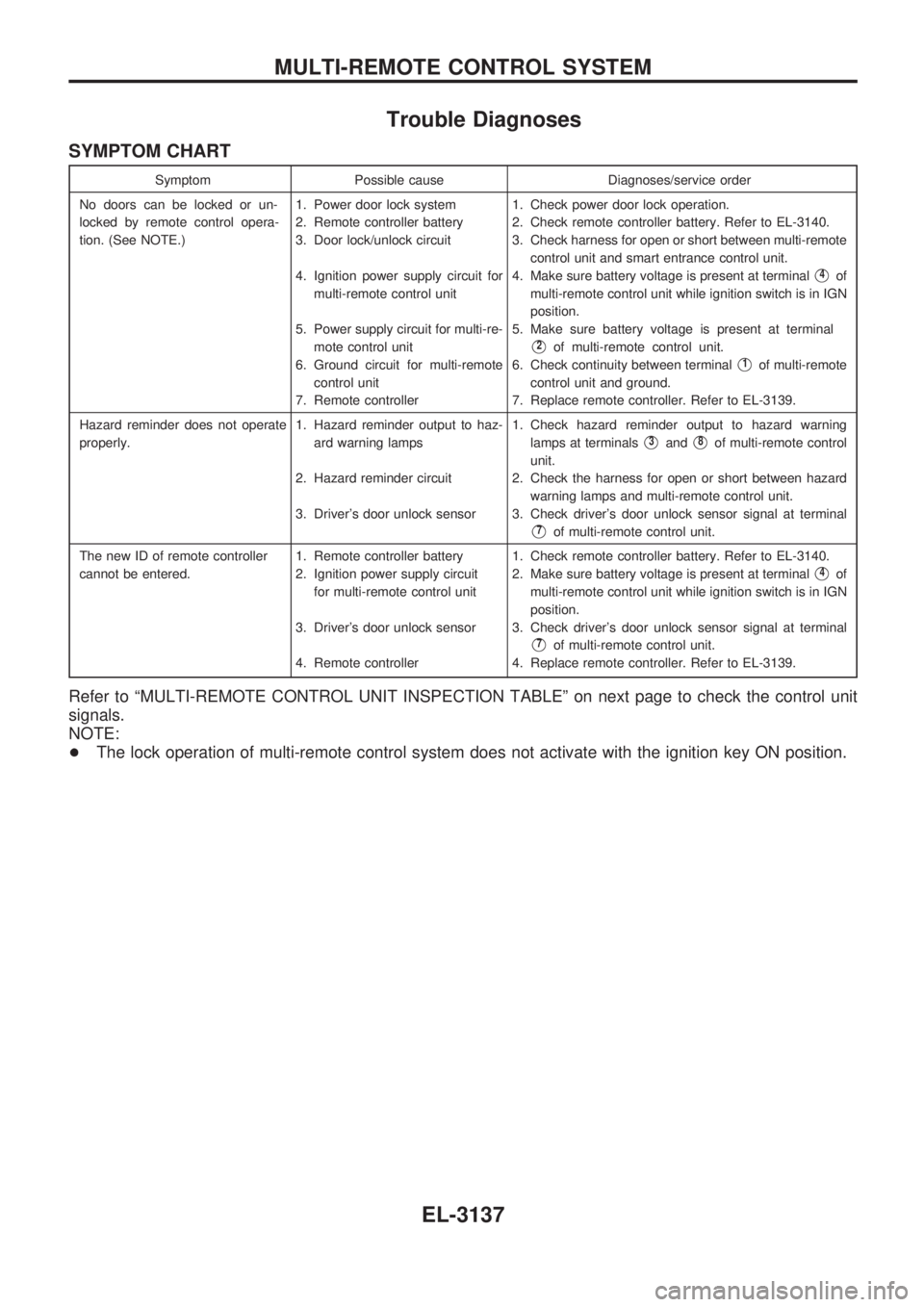
Trouble Diagnoses
SYMPTOM CHART
Symptom Possible cause Diagnoses/service order
No doors can be locked or un-
locked by remote control opera-
tion. (See NOTE.)1. Power door lock system
2. Remote controller battery
3. Door lock/unlock circuit
4. Ignition power supply circuit for
multi-remote control unit
5. Power supply circuit for multi-re-
mote control unit
6. Ground circuit for multi-remote
control unit
7. Remote controller1. Check power door lock operation.
2. Check remote controller battery. Refer to EL-3140.
3. Check harness for open or short between multi-remote
control unit and smart entrance control unit.
4. Make sure battery voltage is present at terminal
V4of
multi-remote control unit while ignition switch is in IGN
position.
5. Make sure battery voltage is present at terminal
V2of multi-remote control unit.
6. Check continuity between terminal
V1of multi-remote
control unit and ground.
7. Replace remote controller. Refer to EL-3139.
Hazard reminder does not operate
properly.1. Hazard reminder output to haz-
ard warning lamps
2. Hazard reminder circuit
3. Driver's door unlock sensor1. Check hazard reminder output to hazard warning
lamps at terminals
V3andV8of multi-remote control
unit.
2. Check the harness for open or short between hazard
warning lamps and multi-remote control unit.
3. Check driver's door unlock sensor signal at terminal
V7of multi-remote control unit.
The new ID of remote controller
cannot be entered.1. Remote controller battery
2. Ignition power supply circuit
for multi-remote control unit
3. Driver's door unlock sensor
4. Remote controller1. Check remote controller battery. Refer to EL-3140.
2. Make sure battery voltage is present at terminal
V4of
multi-remote control unit while ignition switch is in IGN
position.
3. Check driver's door unlock sensor signal at terminal
V7of multi-remote control unit.
4. Replace remote controller. Refer to EL-3139.
Refer to ªMULTI-REMOTE CONTROL UNIT INSPECTION TABLEº on next page to check the control unit
signals.
NOTE:
+The lock operation of multi-remote control system does not activate with the ignition key ON position.
MULTI-REMOTE CONTROL SYSTEM
EL-3137
Page 814 of 1306
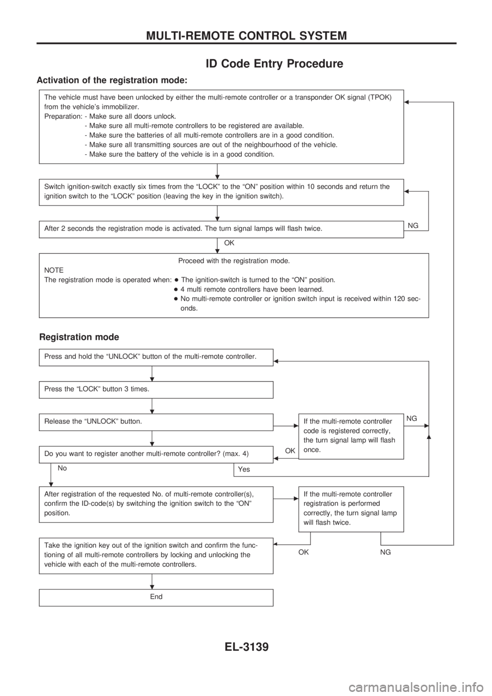
ID Code Entry Procedure
Activation of the registration mode:
The vehicle must have been unlocked by either the multi-remote controller or a transponder OK signal (TPOK)
from the vehicle's immobilizer.
Preparation: - Make sure all doors unlock.
- Make sure all multi-remote controllers to be registered are available.
- Make sure the batteries of all multi-remote controllers are in a good condition.
- Make sure all transmitting sources are out of the neighbourhood of the vehicle.
- Make sure the battery of the vehicle is in a good condition.b
Switch ignition-switch exactly six times from the ªLOCKº to the ªONº position within 10 seconds and return the
ignition switch to the ªLOCKº position (leaving the key in the ignition switch).b
After 2 seconds the registration mode is activated. The turn signal lamps will flash twice.
OKNG
Proceed with the registration mode.
NOTE
The registration mode is operated when:+The ignition-switch is turned to the ªONº position.
+4 multi remote controllers have been learned.
+No multi-remote controller or ignition switch input is received within 120 sec-
onds.
Registration mode
Press and hold the ªUNLOCKº button of the multi-remote controller.b
Press the ªLOCKº button 3 times.
Release the ªUNLOCKº button.cIf the multi-remote controller
code is registered correctly,
the turn signal lamp will flash
once.cNG
Do you want to register another multi-remote controller? (max. 4)
No
Yes
bOK
m
After registration of the requested No. of multi-remote controller(s),
confirm the ID-code(s) by switching the ignition switch to the ªONº
position.cIf the multi-remote controller
registration is performed
correctly, the turn signal lamp
will flash twice.
Take the ignition key out of the ignition switch and confirm the func-
tioning of all multi-remote controllers by locking and unlocking the
vehicle with each of the multi-remote controllers.b
OKNG
End
.
.
.
.
.
.
.
.
MULTI-REMOTE CONTROL SYSTEM
EL-3139
Page 825 of 1306
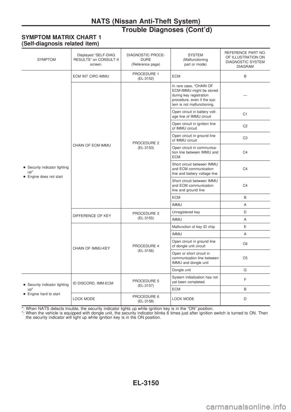
SYMPTOM MATRIX CHART 1
(Self-diagnosis related item)
SYMPTOMDisplayed ªSELF-DIAG
RESULTSº on CONSULT-II
screen.DIAGNOSTIC PROCE-
DURE
(Reference page)SYSTEM
(Malfunctioning
part or mode)REFERENCE PART NO.
OF ILLUSTRATION ON
DIAGNOSTIC SYSTEM
DIAGRAM
+Security indicator lighting
up*
+Engine does not startECM INT CIRC-IMMUPROCEDURE 1
(EL-3152)ECM B
CHAIN OF ECM-IMMUPROCEDURE 2
(EL-3153)In rare case, ªCHAIN OF
ECM-IMMU might be stored
during key registration
procedure, even if the sys-
tem is not malfunctioning.Ð
Open circuit in battery volt-
age line of IMMU circuitC1
Open circuit in ignition line
of IMMU circuitC2
Open circuit in ground line
of IMMU circuitC3
Open circuit in communica-
tion line between IMMU and
ECMC4
Short circuit between IMMU
and ECM communication
line and battery voltage lineC4
Short circuit between IMMU
and ECM communication
line and ground lineC4
ECM B
IMMU A
DIFFERENCE OF KEYPROCEDURE 3
(EL-3155)Unregistered key D
IMMU A
CHAIN OF IMMU-KEYPROCEDURE 4
(EL-3156)Malfunction of key ID chip E
IMMU A
Open circuit in ground line
of dongle unit circuitC6
Open or short circuit in
communication line between
IMMU and dongle unitC5
Dongle unit G
+Security indicator lighting
up*
+Engine hard to startID DISCORD, IMM-ECMPROCEDURE 5
(EL-3157)System initialization has not
yet been completed.F
ECM B
LOCK MODEPROCEDURE 6
(EL-3158)LOCK MODE D
*: When NATS detects trouble, the security indicator lights up while ignition key is in the ªONº position.
*: When the vehicle is equipped with dongle unit, the security indicator blinks 6 times just after ignition switch is turned to ON. Then
the security indicator will light up while ignition key is in the ON position.
NATS (Nissan Anti-Theft System)
Trouble Diagnoses (Cont'd)
EL-3150
Page 828 of 1306
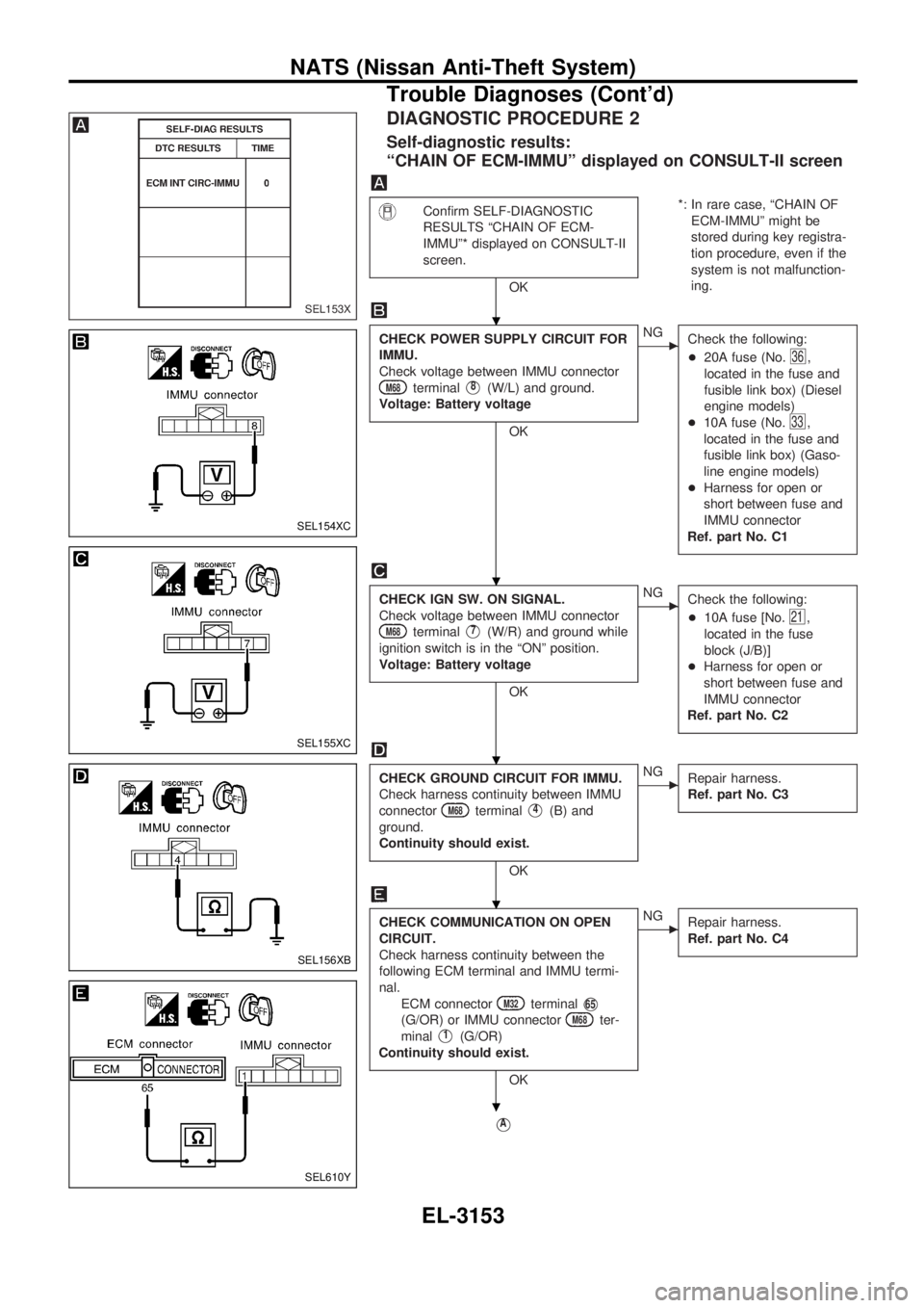
DIAGNOSTIC PROCEDURE 2
Self-diagnostic results:
ªCHAIN OF ECM-IMMUº displayed on CONSULT-II screen
Confirm SELF-DIAGNOSTIC
RESULTS ªCHAIN OF ECM-
IMMUº* displayed on CONSULT-II
screen.
OK*: In rare case, ªCHAIN OF
ECM-IMMUº might be
stored during key registra-
tion procedure, even if the
system is not malfunction-
ing.
CHECK POWER SUPPLY CIRCUIT FOR
IMMU.
Check voltage between IMMU connector
M68terminalV8(W/L) and ground.
Voltage: Battery voltage
OK
cNG
Check the following:
+20A fuse (No.
36,
located in the fuse and
fusible link box) (Diesel
engine models)
+10A fuse (No.
33,
located in the fuse and
fusible link box) (Gaso-
line engine models)
+Harness for open or
short between fuse and
IMMU connector
Ref. part No. C1
CHECK IGN SW. ON SIGNAL.
Check voltage between IMMU connector
M68terminalV7(W/R) and ground while
ignition switch is in the ªONº position.
Voltage: Battery voltage
OK
cNG
Check the following:
+10A fuse [No.
21,
located in the fuse
block (J/B)]
+Harness for open or
short between fuse and
IMMU connector
Ref. part No. C2
CHECK GROUND CIRCUIT FOR IMMU.
Check harness continuity between IMMU
connector
M68terminalV4(B) and
ground.
Continuity should exist.
OK
cNG
Repair harness.
Ref. part No. C3
CHECK COMMUNICATION ON OPEN
CIRCUIT.
Check harness continuity between the
following ECM terminal and IMMU termi-
nal.
ECM connector
M32terminalV65
(G/OR) or IMMU connectorM68ter-
minal
V1(G/OR)
Continuity should exist.
OK
cNG
Repair harness.
Ref. part No. C4
VA
SEL153X
SEL154XC
SEL155XC
SEL156XB
SEL610Y
.
.
.
.
.
NATS (Nissan Anti-Theft System)
Trouble Diagnoses (Cont'd)
EL-3153
Page 1087 of 1306
![NISSAN PICK-UP 2001 Repair Manual HOW TO ERASE SELF-DIAGNOSIS RESULTS
With CONSULT-II
+ªSELF-DIAG [CURRENT]º
A current Self-diagnosis result is displayed on the CONSULT-II screen in real time. After the malfunc-
tion is repaired com NISSAN PICK-UP 2001 Repair Manual HOW TO ERASE SELF-DIAGNOSIS RESULTS
With CONSULT-II
+ªSELF-DIAG [CURRENT]º
A current Self-diagnosis result is displayed on the CONSULT-II screen in real time. After the malfunc-
tion is repaired com](/manual-img/5/57372/w960_57372-1086.png)
HOW TO ERASE SELF-DIAGNOSIS RESULTS
With CONSULT-II
+ªSELF-DIAG [CURRENT]º
A current Self-diagnosis result is displayed on the CONSULT-II screen in real time. After the malfunc-
tion is repaired completely, no malfunction is detected on ªSELF-DIAG [CURRENT]º.
+ªSELF-DIAG [PAST]º
Return to the ªSELF-DIAG [CURRENT]º CONSULT-II screen
by pushing ªBACKº key of CONSULT-II and select ªSELF-
DIAG [CURRENT]º in ªSELECT DIAG MODEº. Touch
ªERASEº in ªSELF-DIAG [CURRENT]º mode.
NOTE:
If the memory of the malfunction in ªSELF-DIAG [PAST]º is
not erased, the User mode shows the system malfunction by
the operation of the warning lamp even if the malfunction is
repaired completely.
+ªTROUBLE DIAG RECORDº
The memory of ªTROUBLE DIAG RECORDº cannot be erased.
Without CONSULT-II
After a malfunction is repaired, return Diagnosis mode to User mode by switching the ignition ªOFFº for at
least 1 second, then back ªONº. At that time, the self-diagnostic result is cleared.
How to Perform Trouble Diagnoses for Quick
and Accurate Repair
A good understanding of the malfunction conditions can make troubleshooting faster and more accurate.
In general, each customer feels differently about a malfunction. It is important to fully understand the symp-
toms or conditions for a customer complaint.
INFORMATION FROM CUSTOMER
WHAT ........ Vehicle model
WHEN ....... Date, Frequencies
WHERE ..... Road conditions
HOW .......... Operating conditions, Symptoms
PRELIMINARY CHECK
Check that the following parts are in good order.
+Battery [Refer to EL section (ªBATTERYº) of Service Manual.]
+Fuse [Refer to EL section (ªFuseº, ªPOWER SUPPLY ROUTINGº) of Service Manual.]
+System component-to-harness connections
SRS701
TROUBLE DIAGNOSES Ð Supplemental Restraint System (SRS)
Trouble Diagnoses Introduction (Cont'd)
RS-3016
Page 1093 of 1306
![NISSAN PICK-UP 2001 Repair Manual If no malfunction is detected on ªSELF-DIAG [CURRENT]º even
though malfunction is detected by the ªAIR BAGº warning lamp,
check the battery voltage.
If the battery voltage is less than 9V, charge NISSAN PICK-UP 2001 Repair Manual If no malfunction is detected on ªSELF-DIAG [CURRENT]º even
though malfunction is detected by the ªAIR BAGº warning lamp,
check the battery voltage.
If the battery voltage is less than 9V, charge](/manual-img/5/57372/w960_57372-1092.png)
If no malfunction is detected on ªSELF-DIAG [CURRENT]º even
though malfunction is detected by the ªAIR BAGº warning lamp,
check the battery voltage.
If the battery voltage is less than 9V, charge the battery. Then
go to DIAGNOSTIC PROCEDURE 4 for final checking, page
RS-3028.
If the battery voltage is OK, go to DIAGNOSTIC PROCEDURE
6, page RS-3032, to diagnose the following situations:
+Self-diagnostic result (previously stored in the memory)
might not be erased after repair.
+The SRS system malfunctions intermittently.
8. Touch ªPRINTº.
9. Compare diagnostic codes to the CONSULT-II DIAGNOS-
TIC CODE CHART, page RS-3023.
10. Touch ªBACKº key of CONSULT-II until ªSELECT SYSTEMº
appears in order to return to User mode from Diagnosis
mode.
11. Turn ignition switch ªOFFº, then turn off and disconnect
CONSULT-II and both battery cables.
12. Repair the system as outlined by the ªRepair orderº in CON-
SULT-II DIAGNOSTIC CODE CHART, that corresponds to
the self-diagnostic result. For replacement procedure of com-
ponent parts, refer to RS-3005 and ªRemoval and Installa-
tionº in RS section of Service Manual (Pub. No. SM9E-
D22BG0) for details.
13. After repairing the system, go to DIAGNOSTIC PROCE-
DURE 4 for final checking, page RS-3028.
SRS701
TROUBLE DIAGNOSES Ð Supplemental Restraint System (SRS)
Self-diagnosis (Cont'd)
RS-3022
Page 1100 of 1306
![NISSAN PICK-UP 2001 Repair Manual 8. Touch ªERASEº.
NOTE:
Touch ªERASEº to clear the memory of the malfunction
(ªSELF-DIAG [PAST]º).
If the memory of the malfunction is ªSELF-DIAG [PAST]º is
not erased, the User mode shows the NISSAN PICK-UP 2001 Repair Manual 8. Touch ªERASEº.
NOTE:
Touch ªERASEº to clear the memory of the malfunction
(ªSELF-DIAG [PAST]º).
If the memory of the malfunction is ªSELF-DIAG [PAST]º is
not erased, the User mode shows the](/manual-img/5/57372/w960_57372-1099.png)
8. Touch ªERASEº.
NOTE:
Touch ªERASEº to clear the memory of the malfunction
(ªSELF-DIAG [PAST]º).
If the memory of the malfunction is ªSELF-DIAG [PAST]º is
not erased, the User mode shows the system malfunction by
the operation of the warning lamp even if the malfunction is
repaired completely.
9. Touch ªBACKº key of CONSULT-II to select ªSELF-DIAG
[PAST]º in the ªSELECT DIAG MODEº screen. Touch ªSELF-
DIAG [PAST]º.
10. Check that no malfunction is detected on ªSELF-DIAG
[PAST]º.
11. Touch ªBACKº key of CONSULT-II until SELECT SYSTEM
appears.
12. Turn ignition switch ªOFFº and then turn off and disconnect
CONSULT-II.
13. Go to DIAGNOSTIC PROCEDURE 1, page RS-3020 to
check SRS operation by using ªAIR BAGº warning lamp with
User mode.
DIAGNOSTIC PROCEDURE 5 (without CONSULT-
II)
Final checking after repairing SRS by using ªAIR BAGº
warning lamp Ð Diagnosis mode and User mode
1. After repairing SRS connect both battery cables.
2. Open driver's door.
3. Turn ignition switch from ªOFFº to ªONº.
4. ªAIR BAGº warning lamp operates in Diagnosis mode as fol-
lows:
SRS701
SRS697
SRS702
SRS800
TROUBLE DIAGNOSES Ð Supplemental Restraint System (SRS)
Self-diagnosis (Cont'd)
RS-3029
Page 1105 of 1306
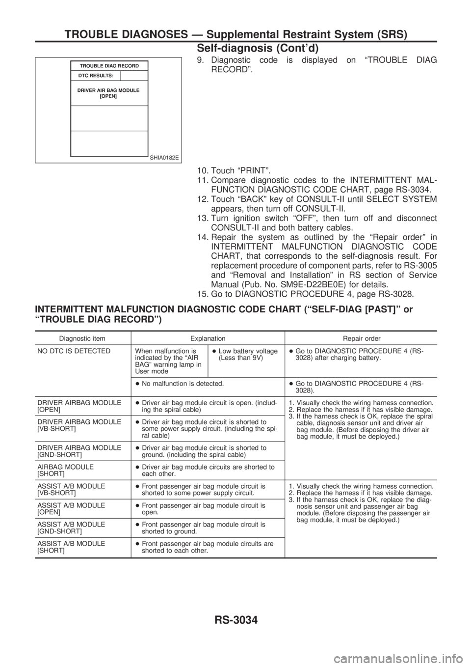
9. Diagnostic code is displayed on ªTROUBLE DIAG
RECORDº.
10. Touch ªPRINTº.
11. Compare diagnostic codes to the INTERMITTENT MAL-
FUNCTION DIAGNOSTIC CODE CHART, page RS-3034.
12. Touch ªBACKº key of CONSULT-II until SELECT SYSTEM
appears, then turn off CONSULT-II.
13. Turn ignition switch ªOFFº, then turn off and disconnect
CONSULT-II and both battery cables.
14. Repair the system as outlined by the ªRepair orderº in
INTERMITTENT MALFUNCTION DIAGNOSTIC CODE
CHART, that corresponds to the self-diagnosis result. For
replacement procedure of component parts, refer to RS-3005
and ªRemoval and Installationº in RS section of Service
Manual (Pub. No. SM9E-D22BE0E) for details.
15. Go to DIAGNOSTIC PROCEDURE 4, page RS-3028.
INTERMITTENT MALFUNCTION DIAGNOSTIC CODE CHART (ªSELF-DIAG [PAST]º or
ªTROUBLE DIAG RECORDº)
Diagnostic item Explanation Repair order
NO DTC IS DETECTED When malfunction is
indicated by the ªAIR
BAGº warning lamp in
User mode+Low battery voltage
(Less than 9V)+Go to DIAGNOSTIC PROCEDURE 4 (RS-
3028) after charging battery.
+No malfunction is detected.+Go to DIAGNOSTIC PROCEDURE 4 (RS-
3028).
DRIVER AIRBAG MODULE
[OPEN]+Driver air bag module circuit is open. (includ-
ing the spiral cable)1. Visually check the wiring harness connection.
2. Replace the harness if it has visible damage.
3. If the harness check is OK, replace the spiral
cable, diagnosis sensor unit and driver air
bag module. (Before disposing the driver air
bag module, it must be deployed.) DRIVER AIRBAG MODULE
[VB-SHORT]+Driver air bag module circuit is shorted to
some power supply circuit. (including the spi-
ral cable)
DRIVER AIRBAG MODULE
[GND-SHORT]+Driver air bag module circuit is shorted to
ground. (including the spiral cable)
AIRBAG MODULE
[SHORT]+Driver air bag module circuits are shorted to
each other.
ASSIST A/B MODULE
[VB-SHORT]+Front passenger air bag module circuit is
shorted to some power supply circuit.1. Visually check the wiring harness connection.
2. Replace the harness if it has visible damage.
3. If the harness check is OK, replace the diag-
nosis sensor unit and passenger air bag
module. (Before disposing the passenger air
bag module, it must be deployed.) ASSIST A/B MODULE
[OPEN]+Front passenger air bag module circuit is
open.
ASSIST A/B MODULE
[GND-SHORT]+Front passenger air bag module circuit is
shorted to ground.
ASSIST A/B MODULE
[SHORT]+Front passenger air bag module circuits are
shorted to each other.
SHIA0182E
TROUBLE DIAGNOSES Ð Supplemental Restraint System (SRS)
Self-diagnosis (Cont'd)
RS-3034